Week 5
Electronics Design
Part 1: Simple Starting Case
Goal: use an EDA tool to design a development board to interact and communicate with an embedded microcontroller.
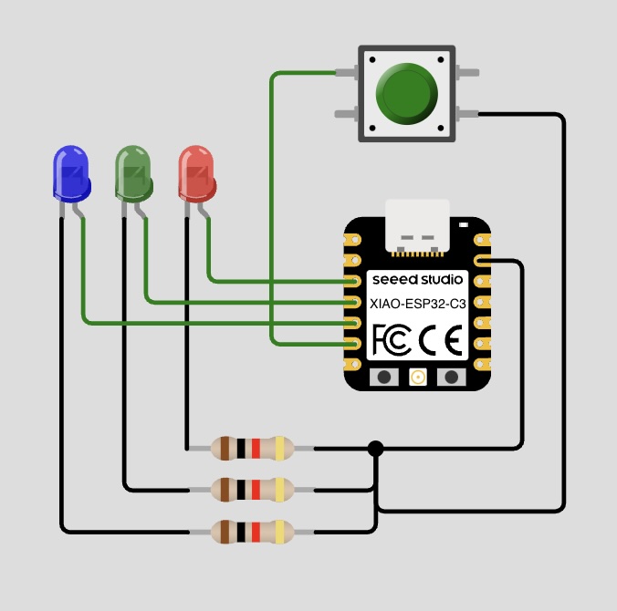
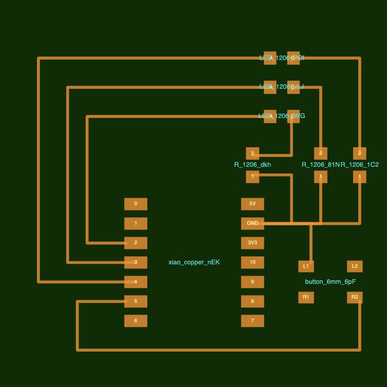
Having never designed a PCB before, I decided to begin with something simple. I started off with a simple simulation of my circuit in Wokwi, which I then translated into a PCB design using SVG-PCB (here). This tooling was super helpful as a beginner, and allowed me to quickly translate my simulated circuit into a PCB design.
Part 2: Using KiCad
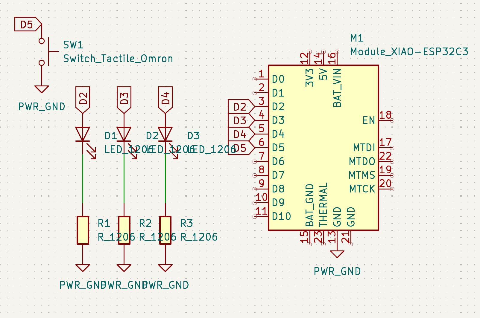
I started off making this same simple design, but this time using KiCad. Using the schematic editor, I first added the necessary components to my design and then connected them.
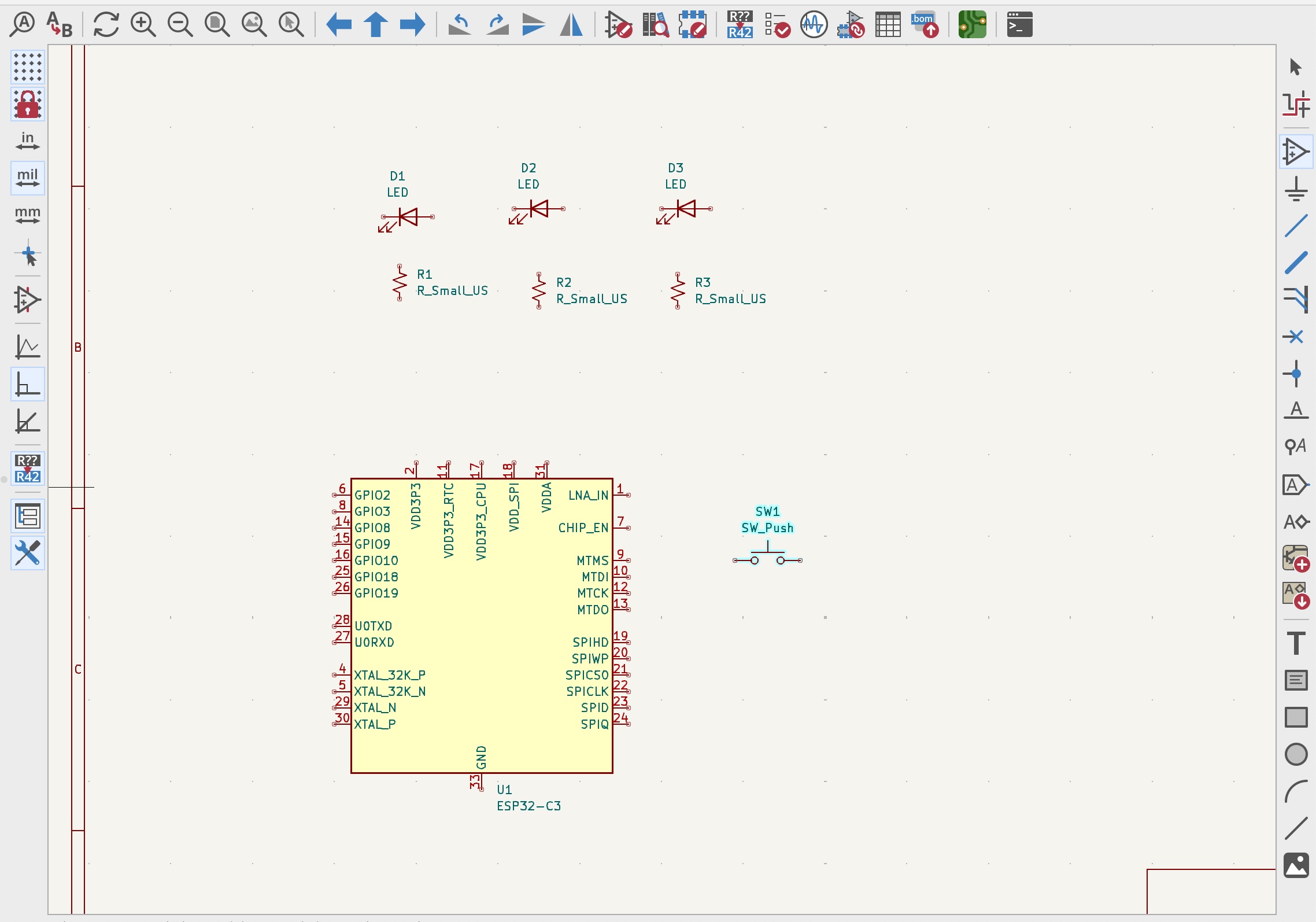
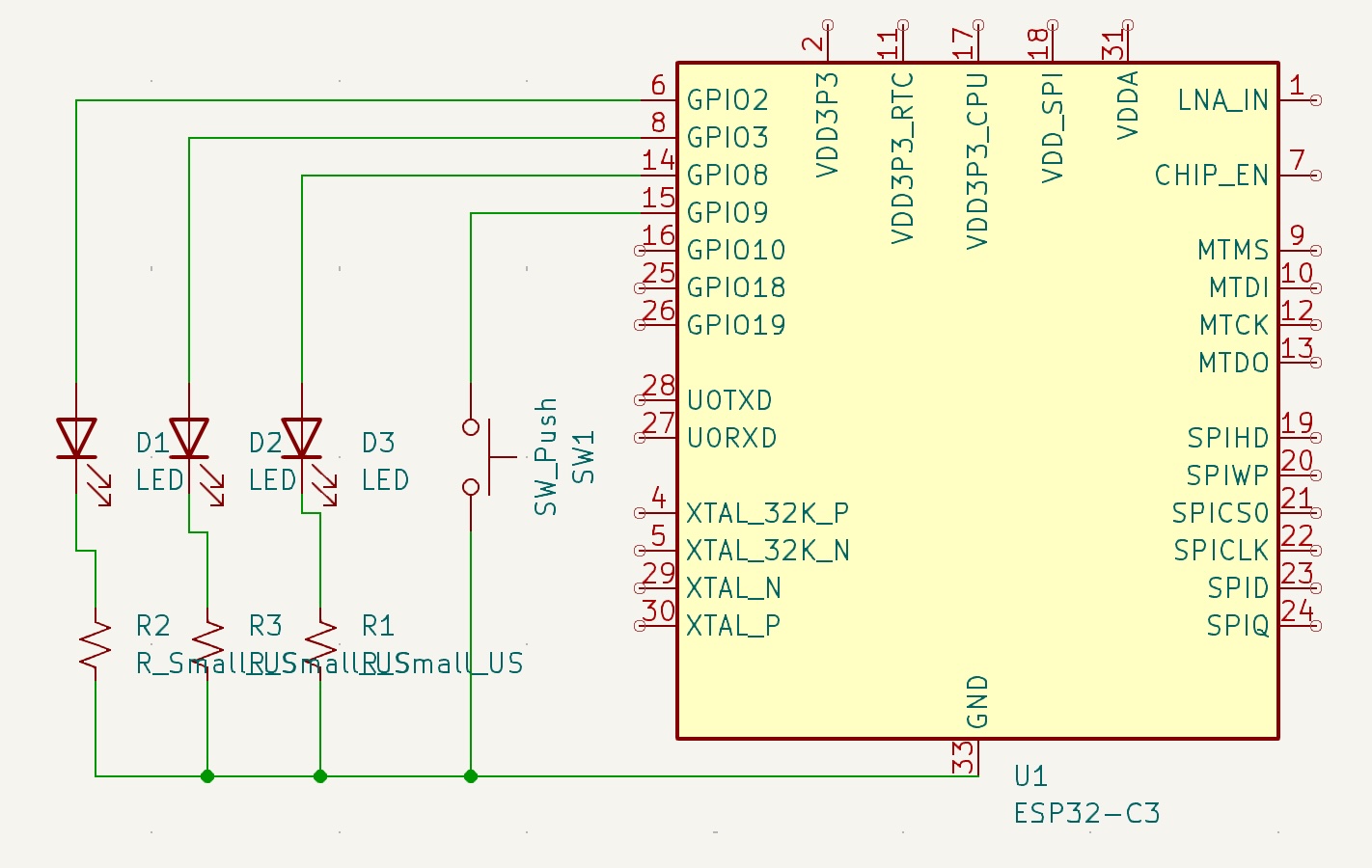
After this, I was able to get the Fab Academy library into KiCad, which gave me the parts that are available in inventory for this class. Based on that, I switched out the processor to the Xiao ESP32C3, which is also the microprocessor I used to do the initial modeling in Wokwi. This is the library I connected (here).
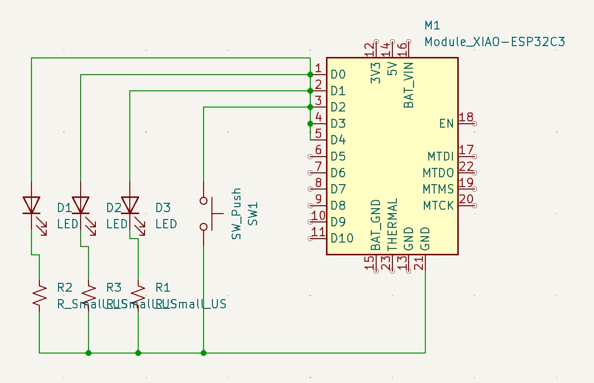
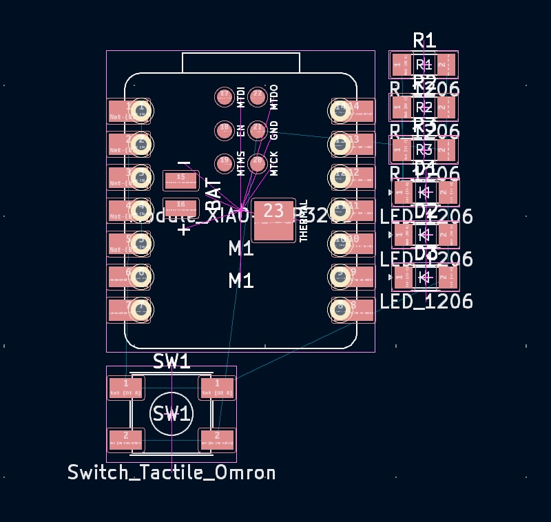
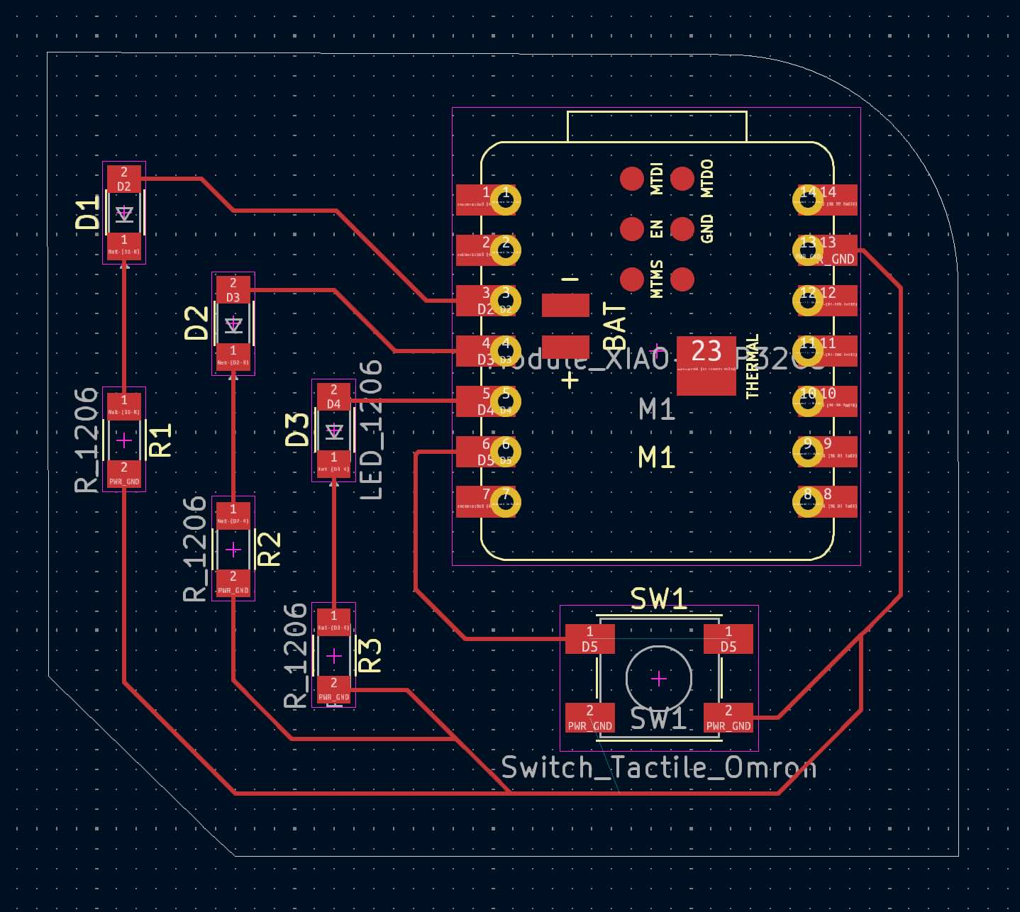
Next, I went to the PCB editor to work on the layout for the different components. I realized while doing this had I'd done the schematic entirely with wires, and wanted to go back and use more labels to connect things (even though this PCB isn't that complication) Here is the original layout from the PCB editor (after some de-tangling):
This is the new schematic, using a combination of wires and labels:
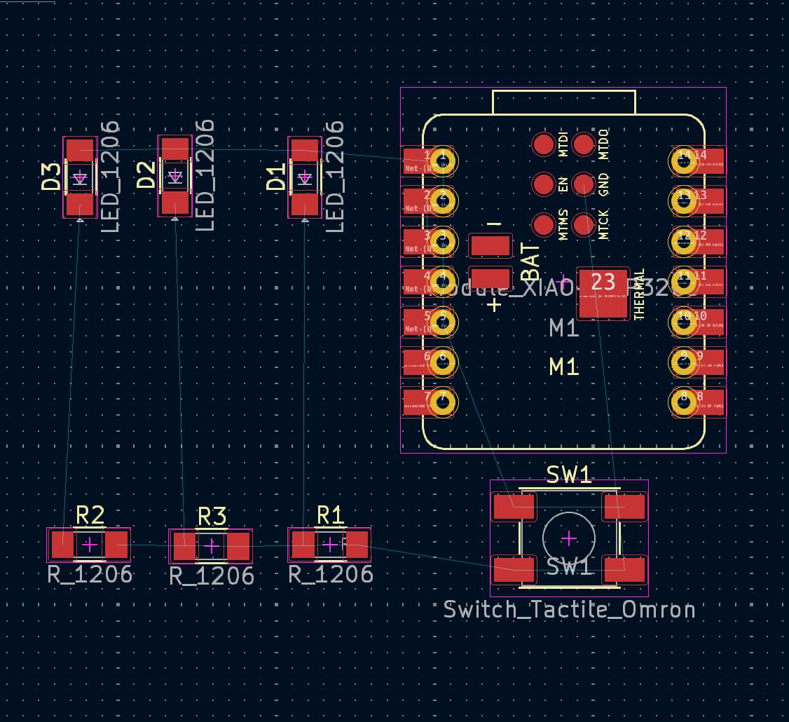
I then went back to the PCB Editor to work on the layout and ended up with this:
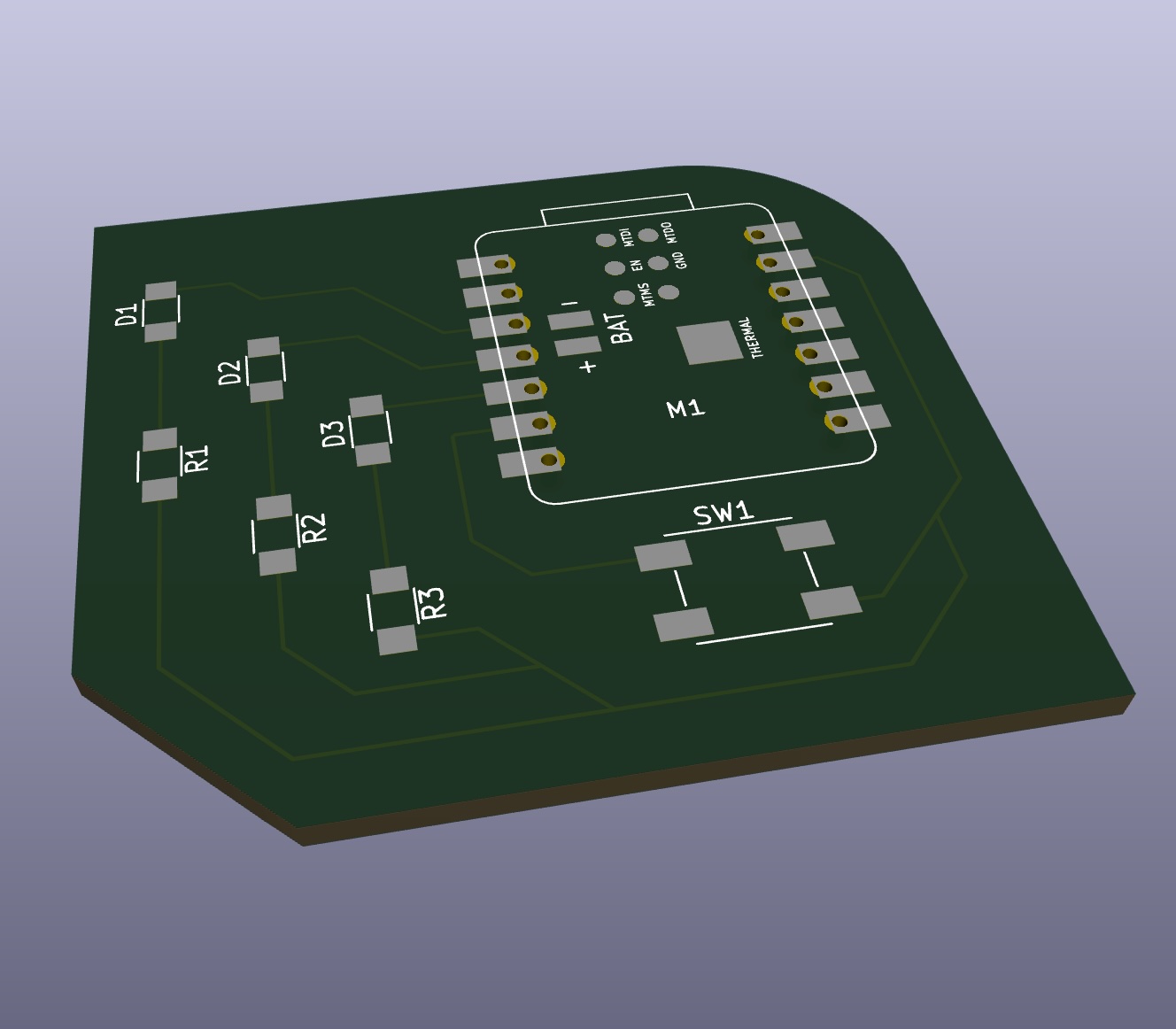
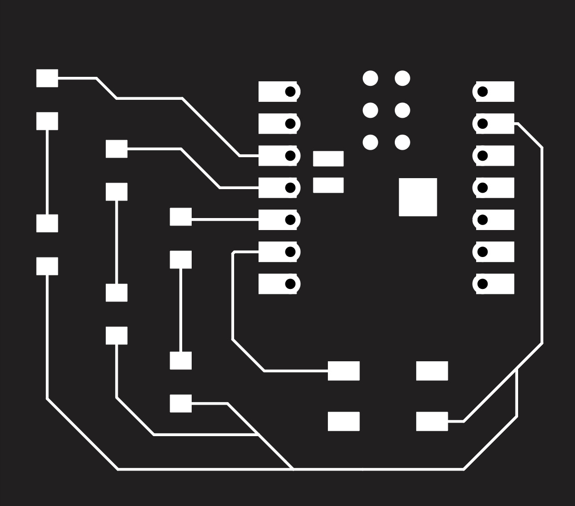
To get this in a mill-able format, I then exported to an SVG file:
