Week 6
Electronics Production
Part 1: Updating PCB Design
I started off with the PCB design I created last week:
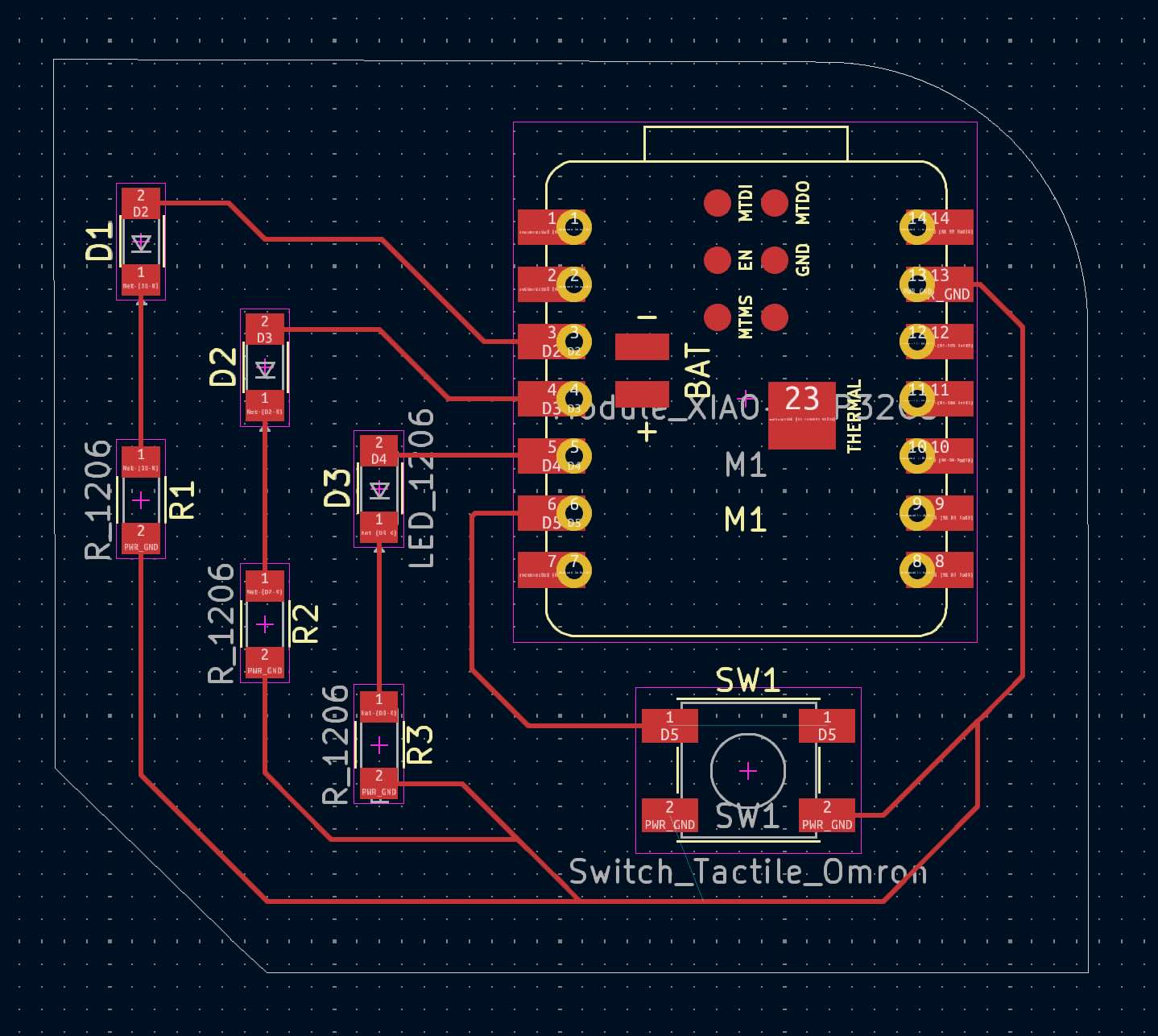
However, now that I'm actually milling it, I realized some of the parameters were incorrect. Primarily, I went back and adjusted the clearance and track width (file -> board setup -> net classes), changing both of these to 0.5 since this is a farily simple board. I also changed the edge cut, so that the USB-C would be hanging off the edge of the board.
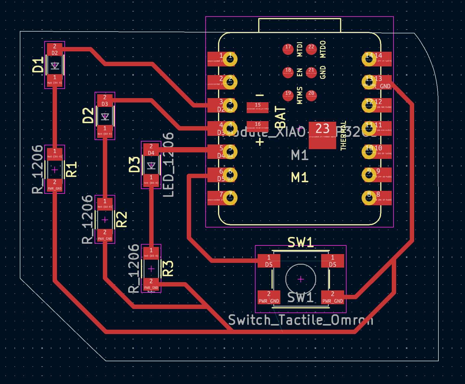
I then exported this as an SVG file, and inverted the colors to work correctly with the milling machine. That left me with these two files:


Part 2: Milling a PCB
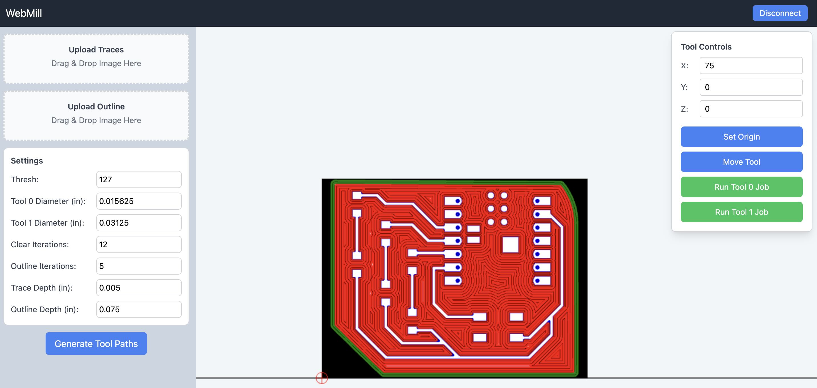
I used (this) software to mill the PCB. I used a 1/64 inch endmill to mill the traces, and a 1/32 inch endmill to mill the edge cuts. After putting the correct bits into the machine, I set the location using the tools control, zeroing the machine, and uploaded the traces and outline.
Here is the setup in the milling software:
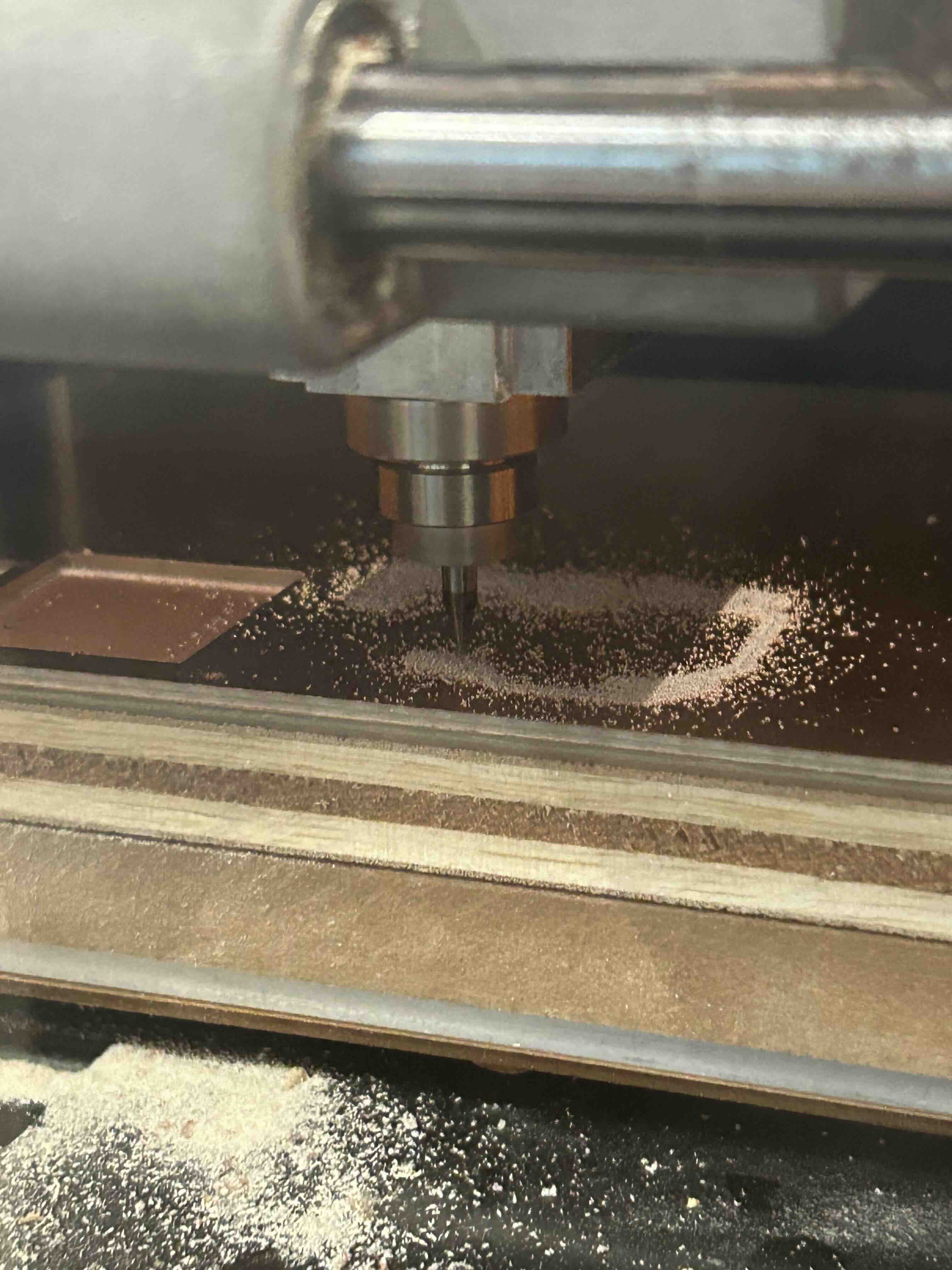
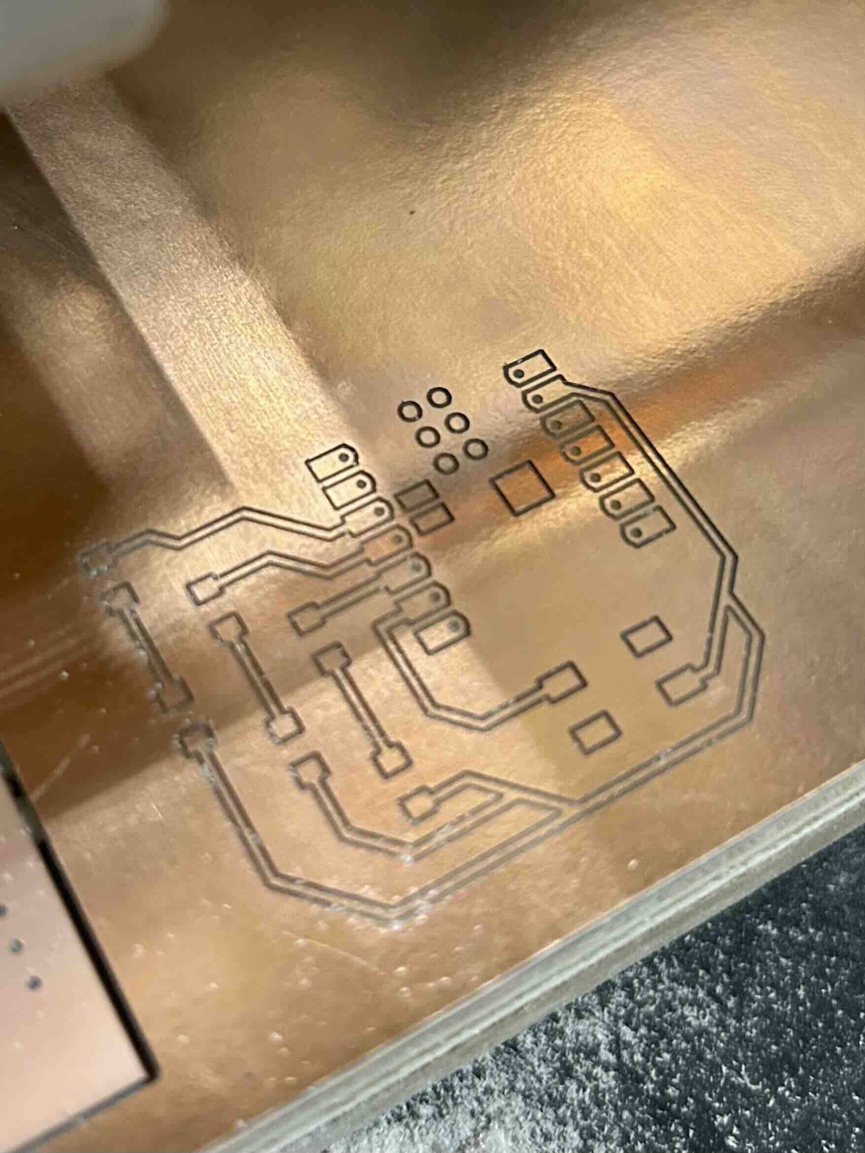
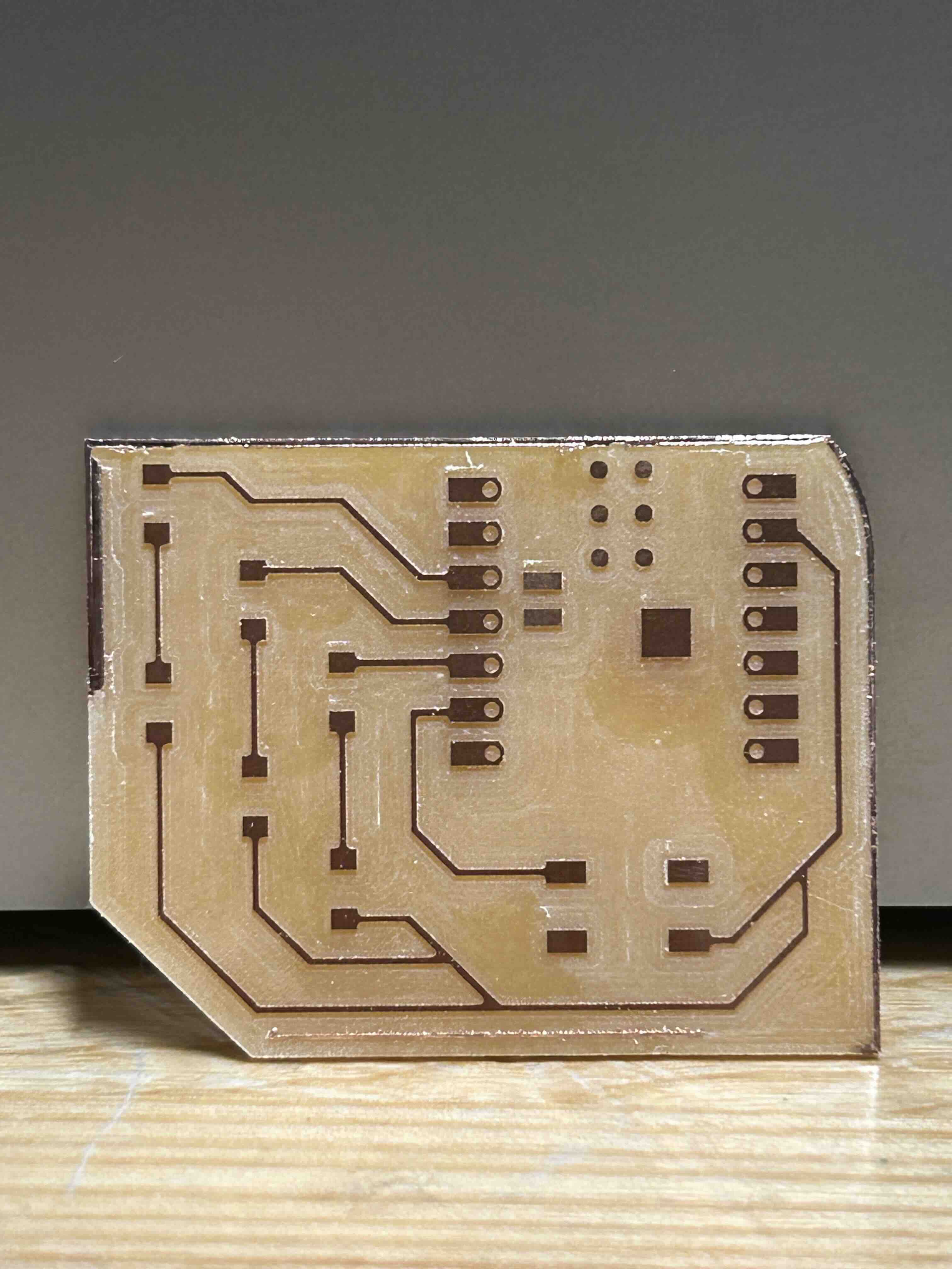
Here is (1) the milling machine starting, (2) the traces after "Run Tool 0 Job", and (3) the finished PCB after "Run Tool 1 Job":
Part 3: Soldering
Next is soldering! I've never done anything with electronics before (even a bread board), so this was quite exciting :) I learned how to generally position the soldering iron and feed in the wire to get a good joint, and was surprised how small some of the components were.

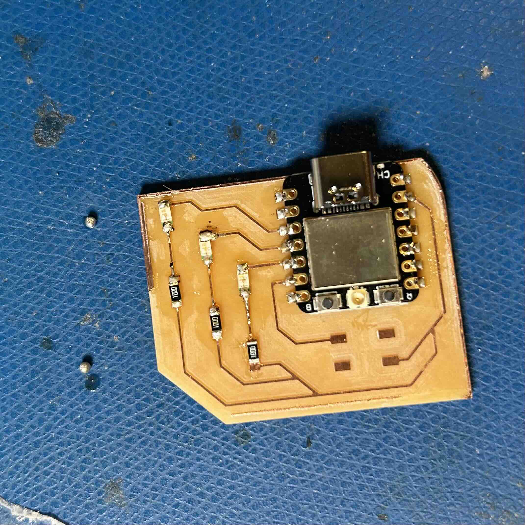
Finally the board was complete!

Part 4: Software
The last step was plugging this into my computer and uploading the code. I downloaded the Arduino IDE and added the ESP32 board package to the IDE following the instructions here to add the package_ESP32_index.json. I then uploaded the code that I had used in the Wokwi simulation (see week 3, embedded programming).