Part 1: Vinyl Cutting
I decided to make a sticker from some Chinese characters using vinyl cutting. I came across an image that I really like, and traced it in Inkscape to get a vector image.

The characters mean "peaceful and happy", which is a Chinese blessing. May we all live a peaceful and happy life!
It turned out that the vinyl cutter has a pre-written program (mods) that can process a png image, so the previous tracing step was not necessary.
Since I already traced it, I used mods to process the svg image.
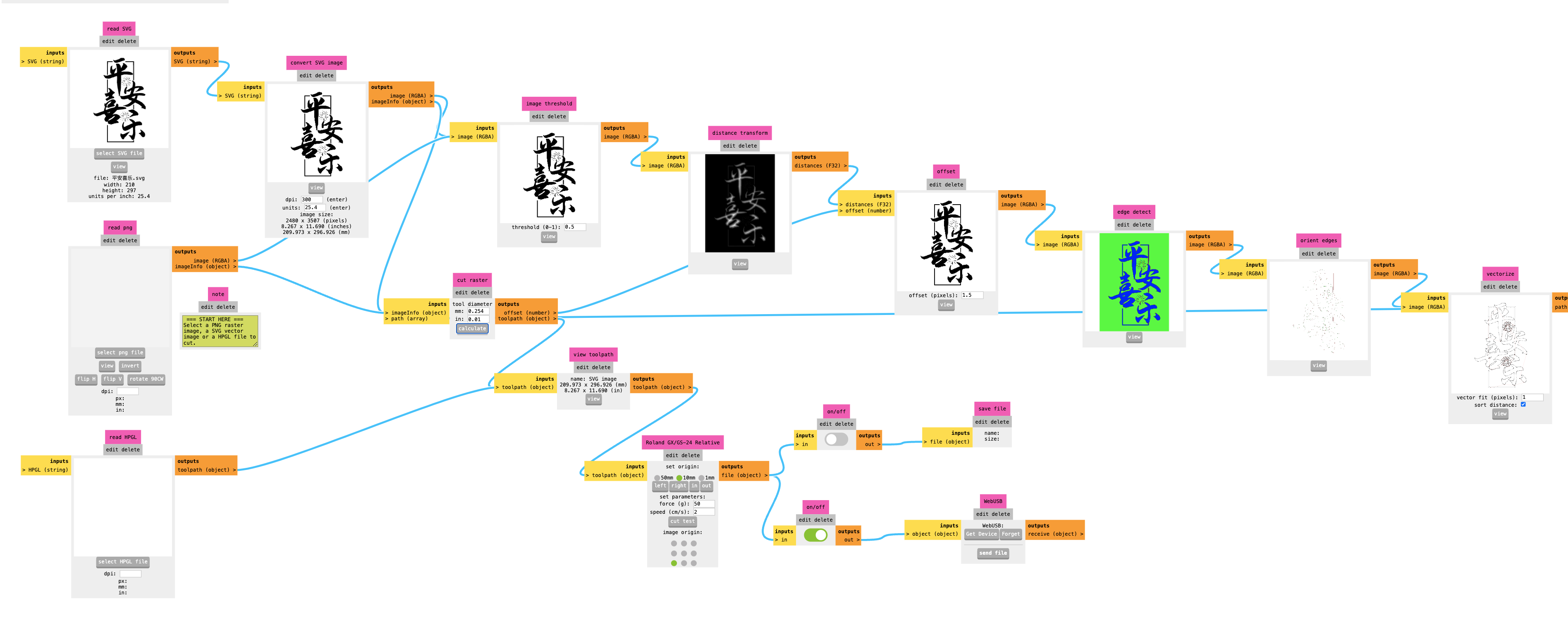
The firework features were too small and didn't turn out good, and the outer frame did not stick on the backing after cutting, but all the other features were clearly cut as shown below:
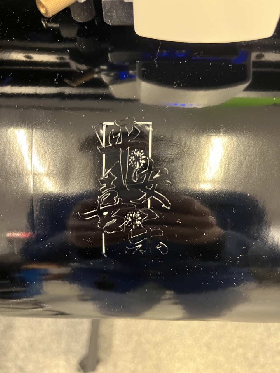
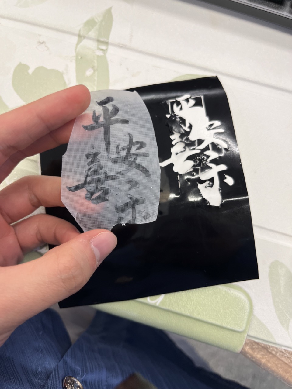
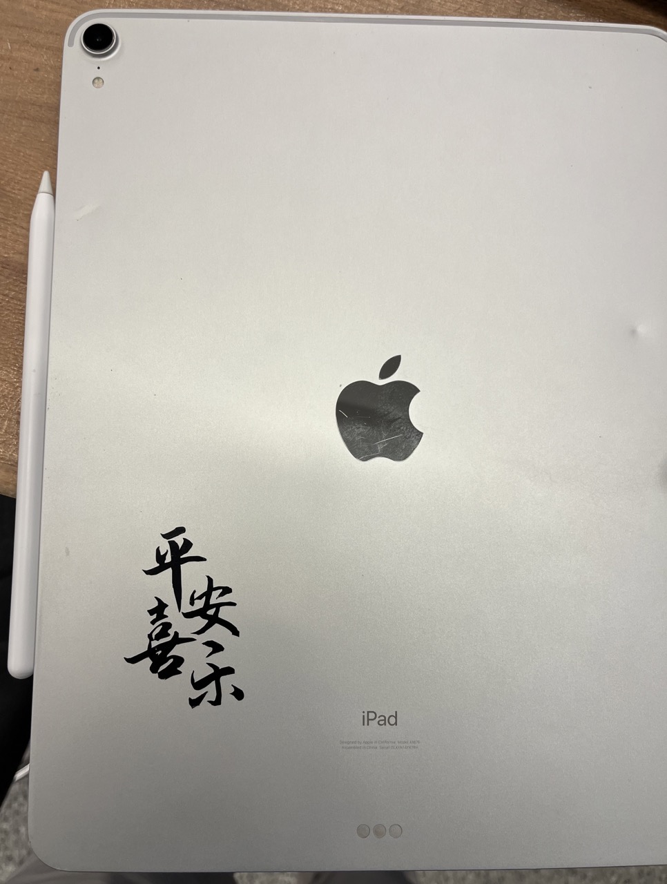
It seems that every line was cut twice, so I got some very thin traces on the edges. This could be because of the way the program processed the svg image, which can be investigated in the future.
Part 2: Laser Cutting
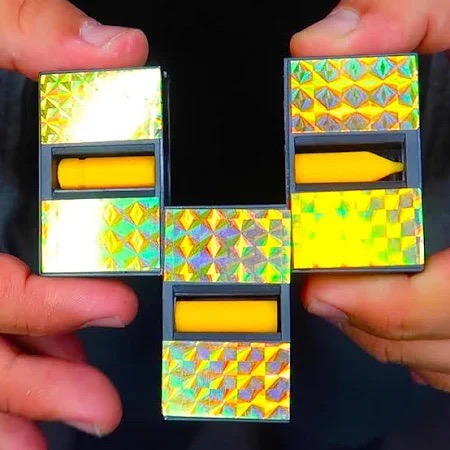
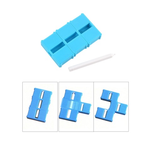
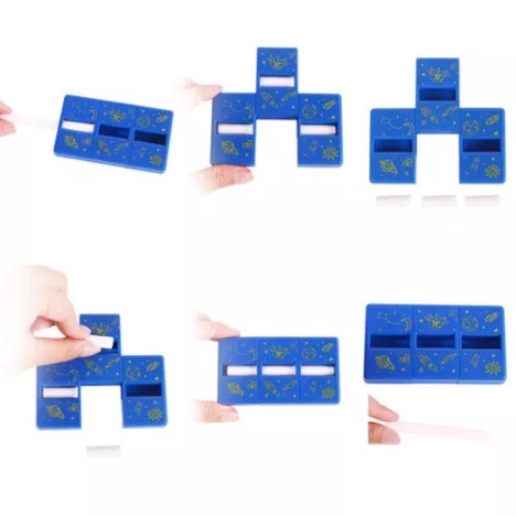
Have you seen a magic zig-zag box that can cut a pencil into three pieces, and then restore it completely? Some examples are shown below:
Here's the trick behind the magic box:
Besides having a big compartment for an intact pencil, the box also has three additional smaller compartments around it to store three pre-cut pencil pieces. When we shifted the outer shells, the windows on the shells moved between the top of the big compartment and that of the three smaller compartments, creating an illusion that the pencil was cut into or restored from three pieces.
This week, I decided to make one such box using laser cutting.
Materials/Components
- Cardboard
Machines/Tools
- Universal Laser Cutter 60 watt
Design Files
- CAD: f3d download
Hand Sketch
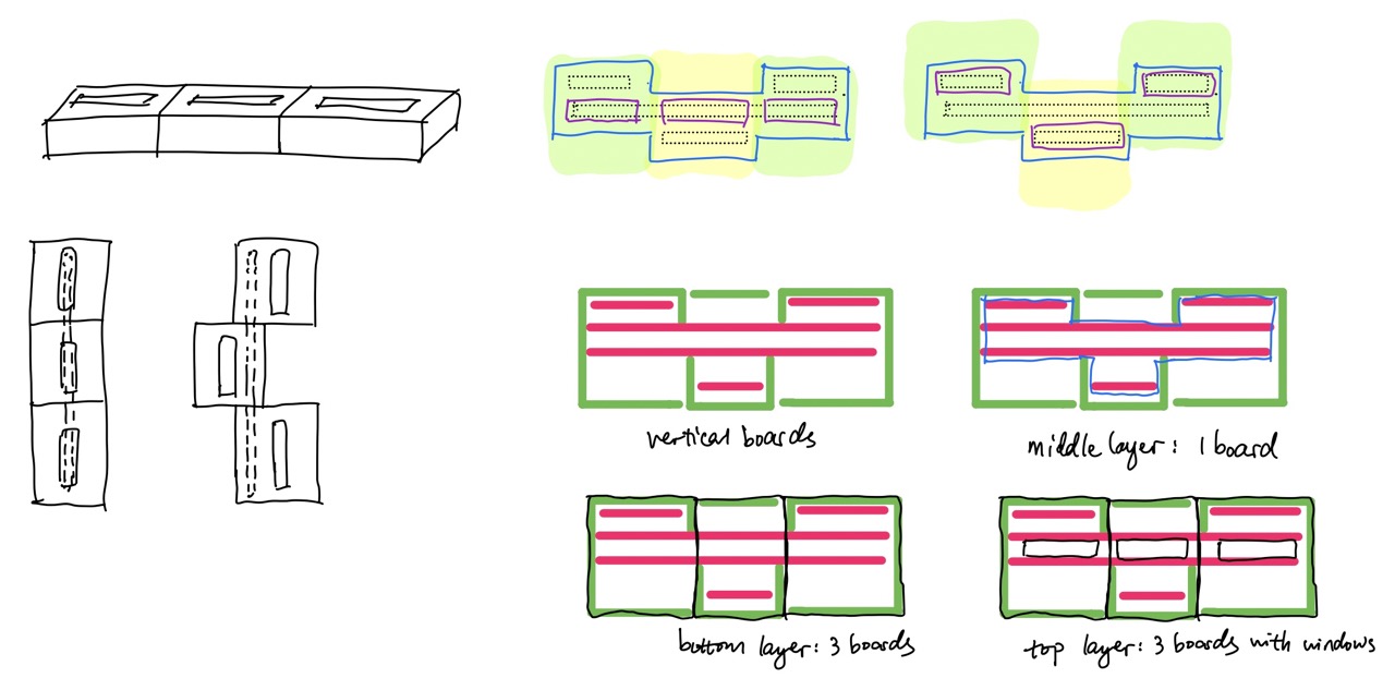
Here I sketched out the box structure:
Modeling
Before taking the class, I had some CAD experiences with both SOLIDWORKS and Fusion 360, but only after coming to the class did I know that I missed one super important designing tool: parametric modeling, which means assigning dimensions with variables (parameters) instead of pure numbers. Thinking back it was quite funny because I did a lot of my previous CAD works using direct modeling, and modifying the dimensions, saving different versions, and keeping track of them were quite a pain. Now I realized that with parametric modeling, all we need to do is to change the values of the parameters and save them.
With the principles of parametric modeling in mind, the designing process was also a lot easier. I assigned a lot of dimensions using the relationship between parameters, and even the values of parameters themselves can be an equation instead of a number. This saved me a lot of calculation time.
Structures: Inner pencil holder & Outer shells with windows
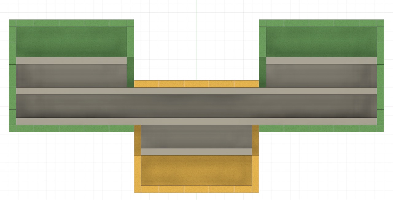
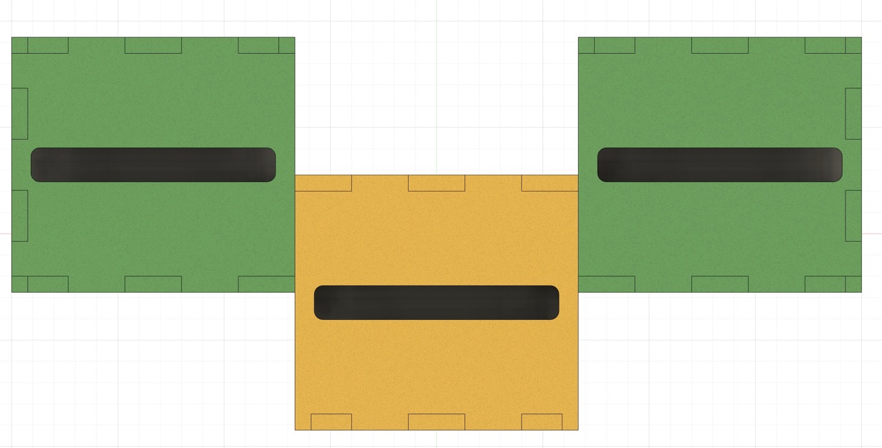
The following images show outer three shells, the inner pencil holder with slots for an intact pencil and three pencil pieces, and the assembled pieces with the top covers removed for clarity.
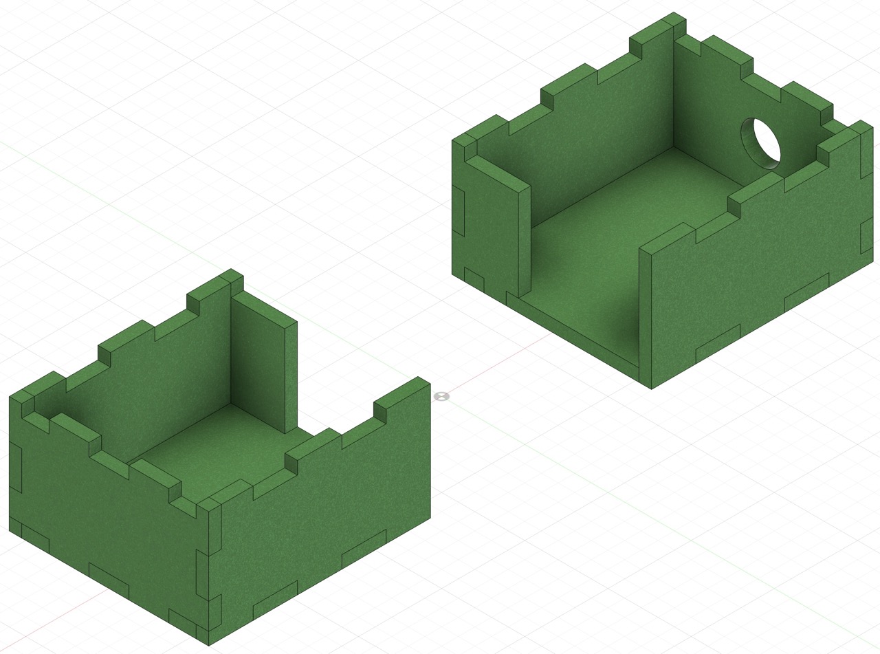
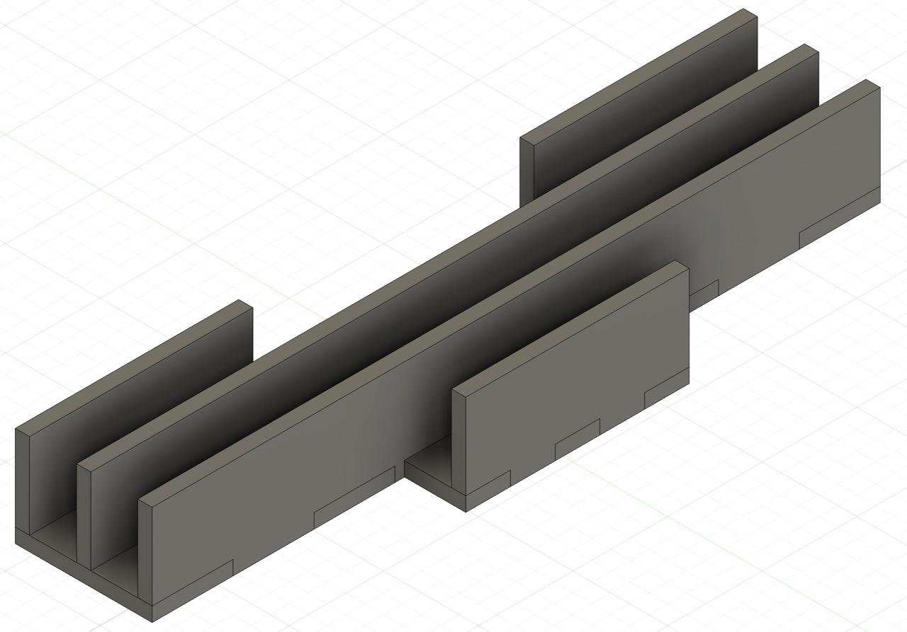
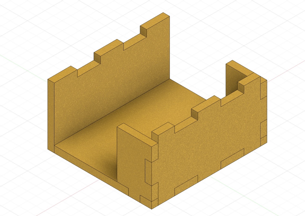
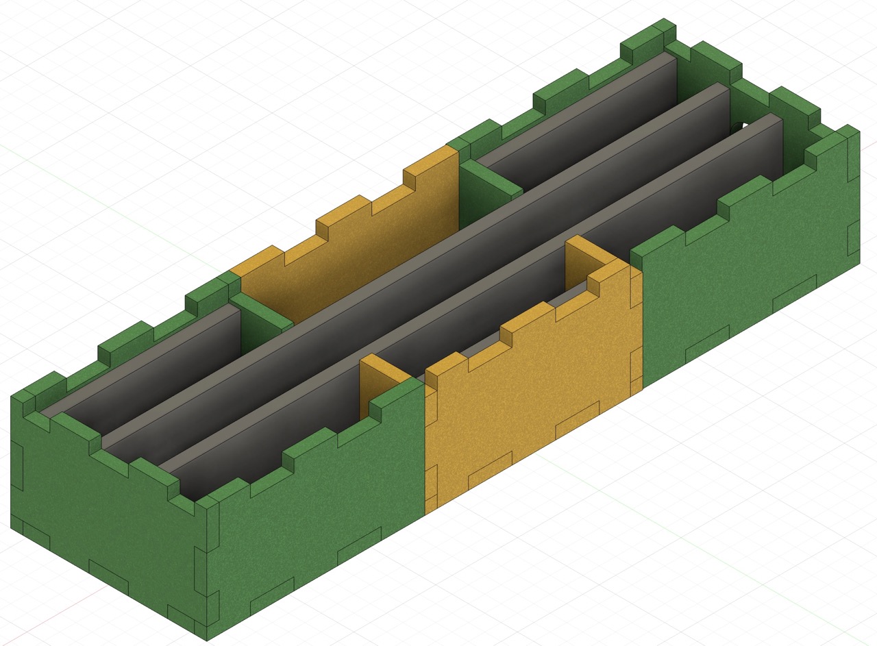
The outer shells can slide relative to the inner holder, and the initial position and the "cut position" were shown in the images below:


Sequence of Modeling
I constructed all the pieces without joints first to visualize the entire structure, and added the joints between boards afterwards. Imagining the joint structures could be hard, especially at the intersection between three faces, even though I was only doing the simpliest press-fit joint. Therefore, instead of sketching the joints on each piece, I used one body's joints to cut the other body at every intersection. This eased the joint designing process, but made adding laser offset difficult at this stage.
Cutting and Tuning
I tried to laser cut the design and constructed the box, but as expected, the joints were not tight enough to hold the structure well.
Since adding offset in my original design was difficult, I re-imported all the dxf files into another design in Fusion 360, and added an offset to all edges.
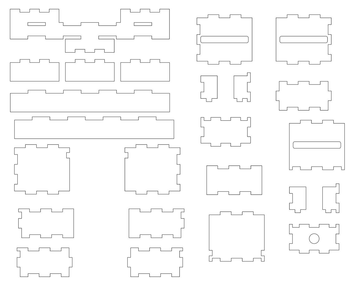
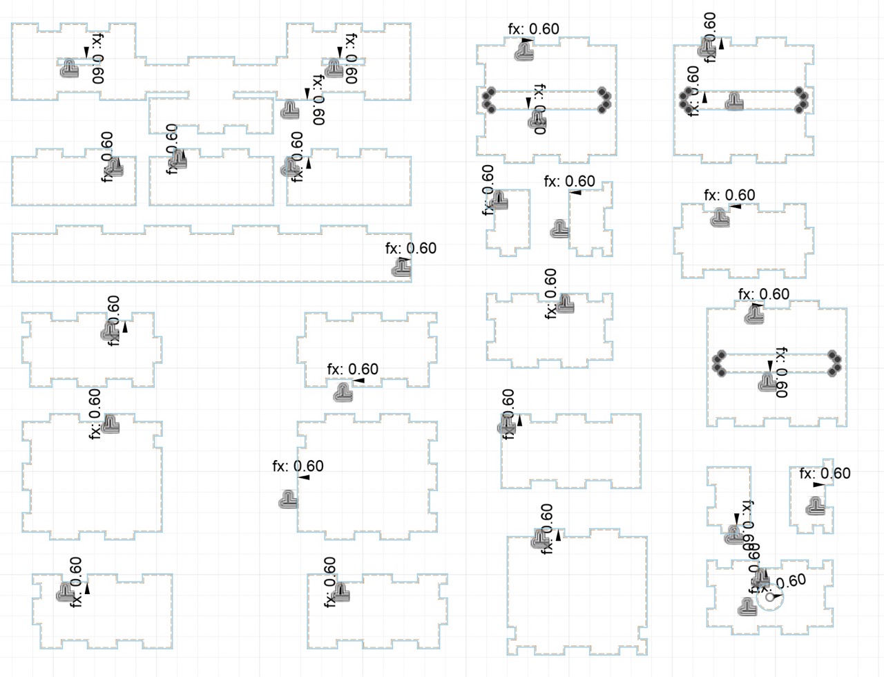
I set the offset to 0.6 mm and laser cut the design again. This time, the joints were too big to fit with each other, but combining the pieces from my first cut and second cut, I was able to construct the box!
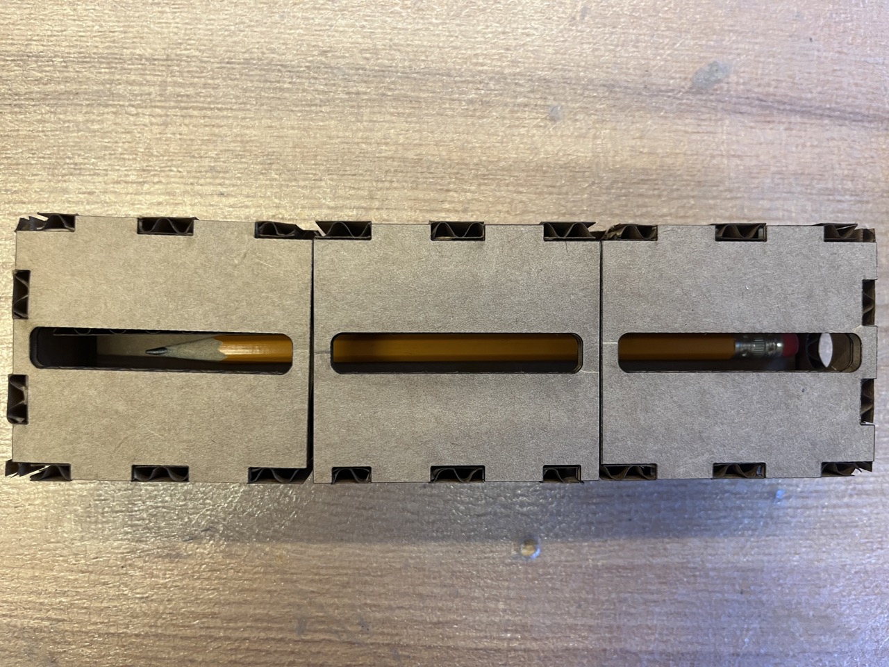
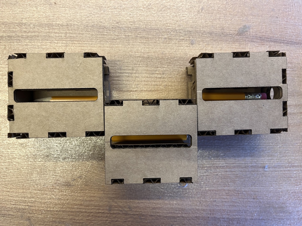
I had to take off the small vertical boards in between the three shells for the pieces to fit, but the magic works:
In the future, more confinement in the inner holder can be added to prevent the three pencil pieces from falling out.
Parameters used
| Board thickness | 3.8 mm |
|---|---|
| Laser cutter power | 100% |
| Laser cutter speed | 19% |
| Laser cutter PPI | 1000 |
Acknowledgements
I would like to express my greatest gratitude for Anthony, who toured me through the lab and trained me on the laser cutter, and Yuval, who helped me with website constructing, magic box building, and vinyl cutting!
