Goal: Design and build a chandelier with a grid of lights that move up and down as controlled by the input of a user's hand waving over a nearby sensing control pad.
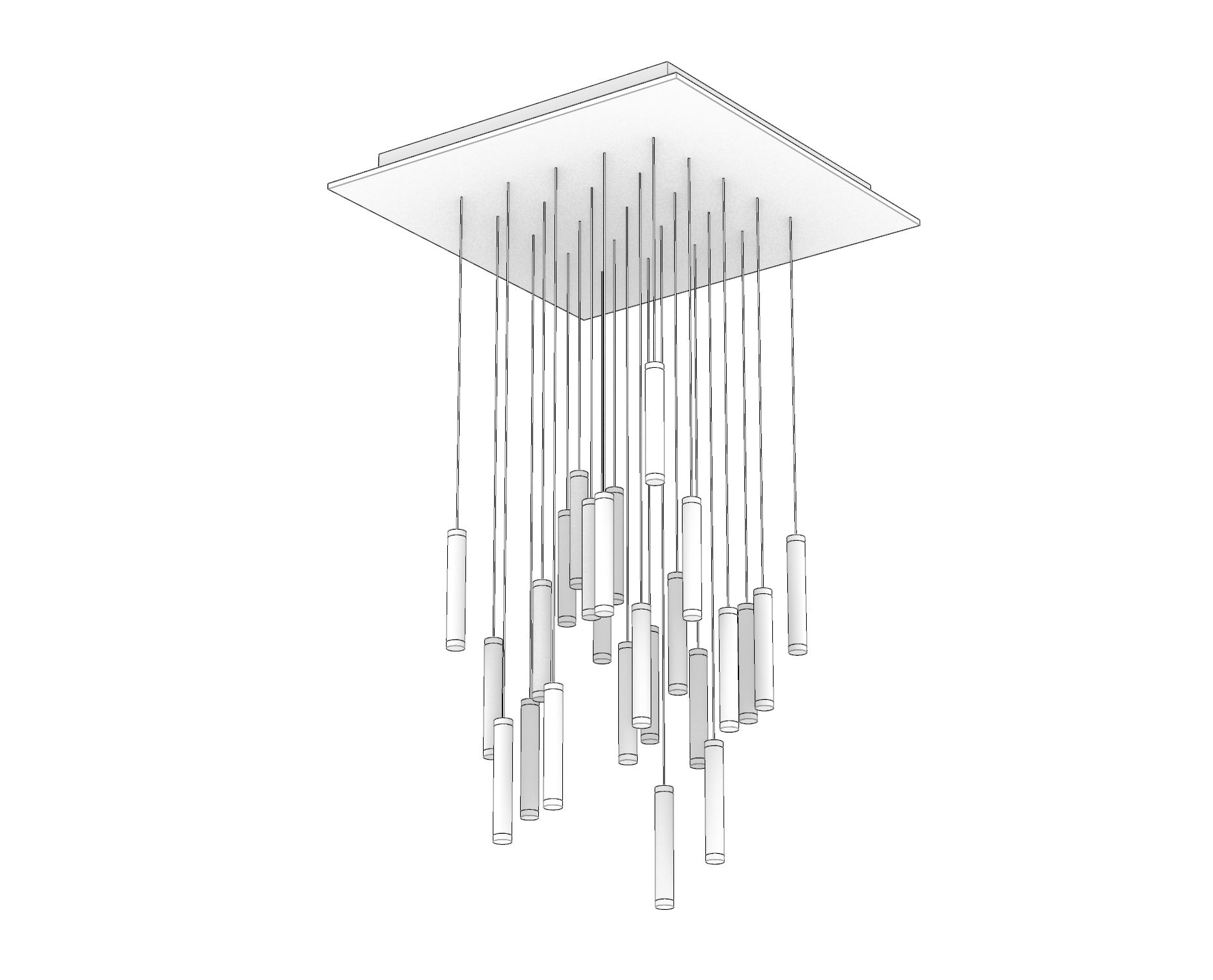
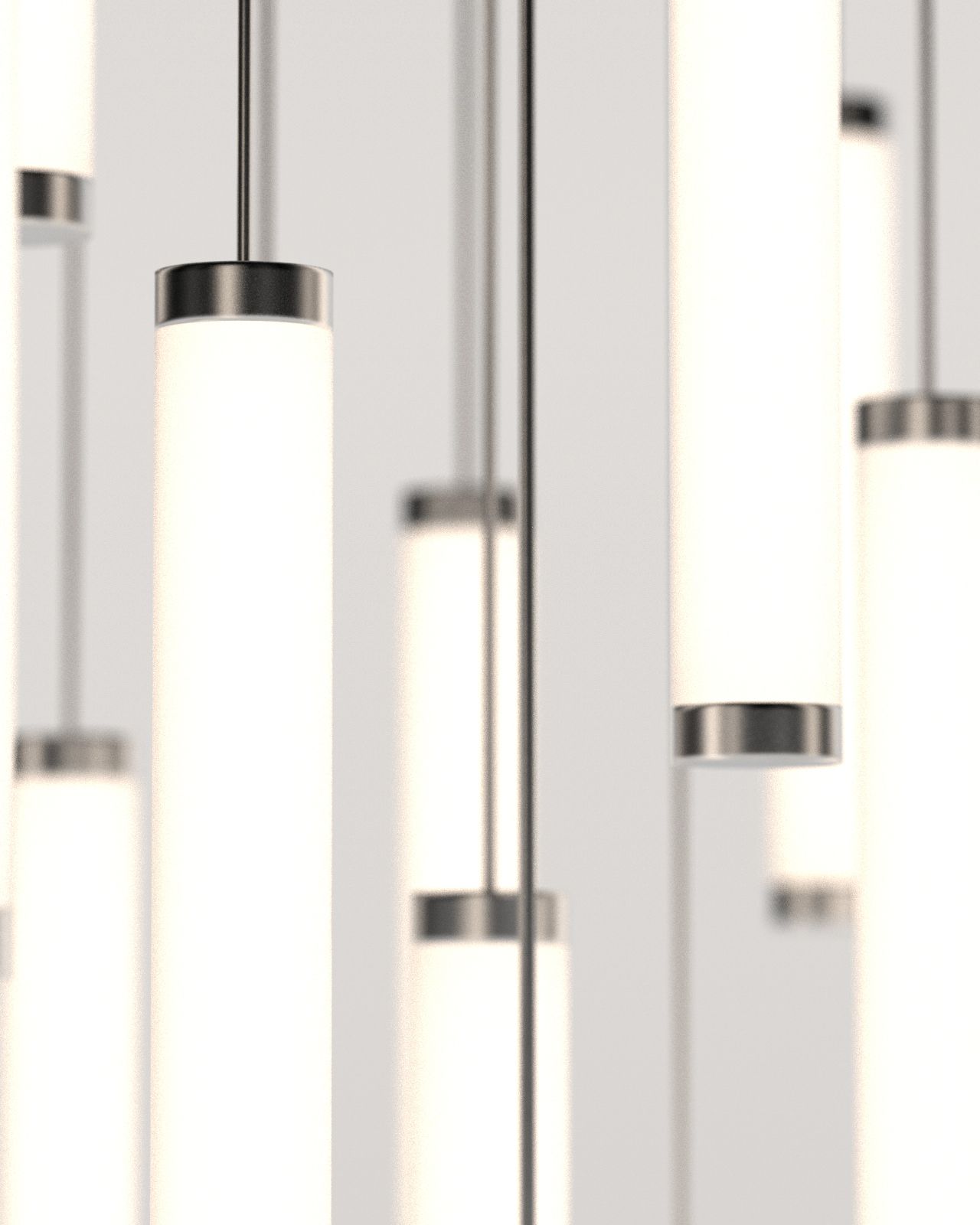
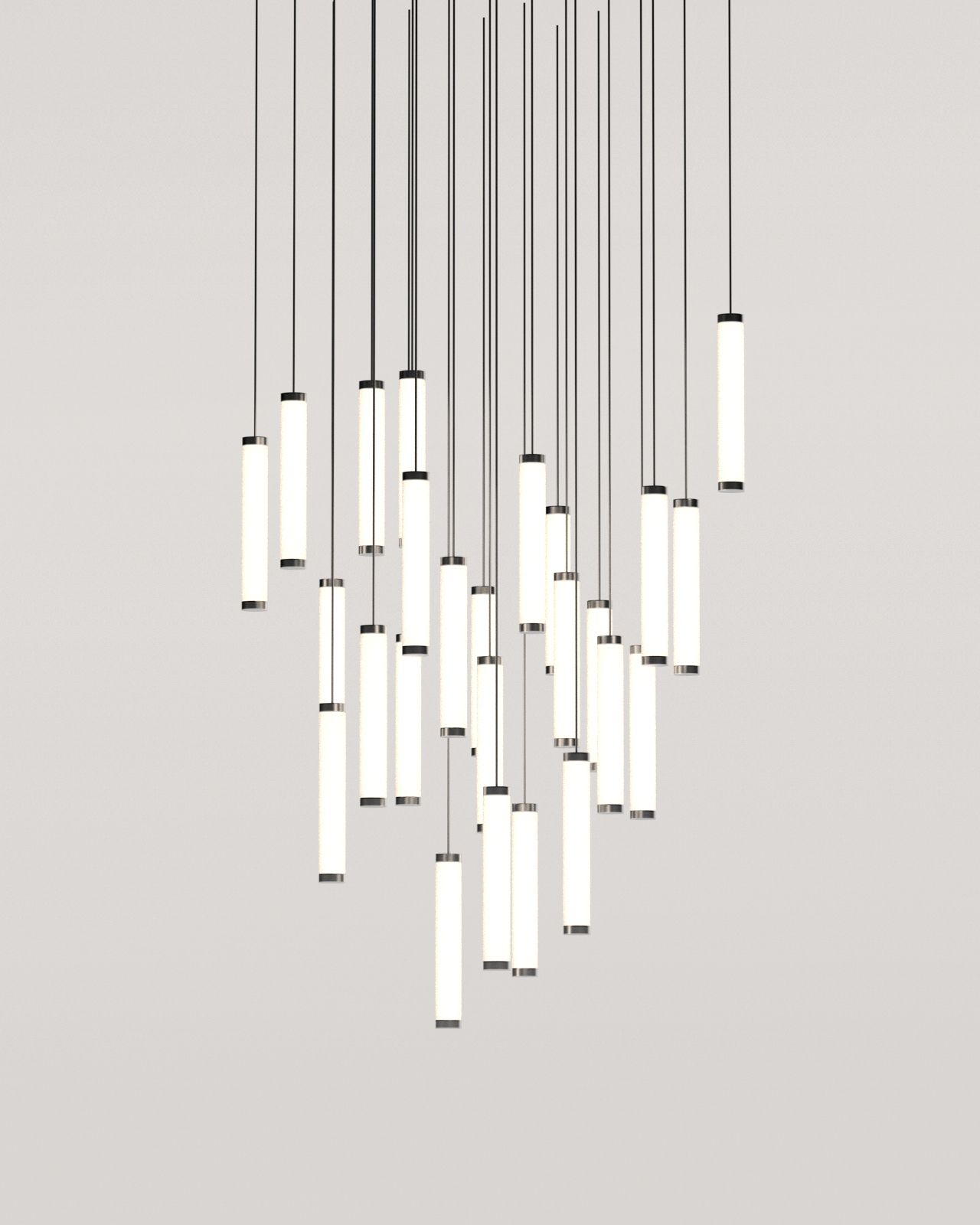
These renders above represent the first iteration of my design for the chandelier. There is an ambitious grid of 25 hanging lights (5x5). This might be scaled back depending on how much I'm able to accomplish this semester.
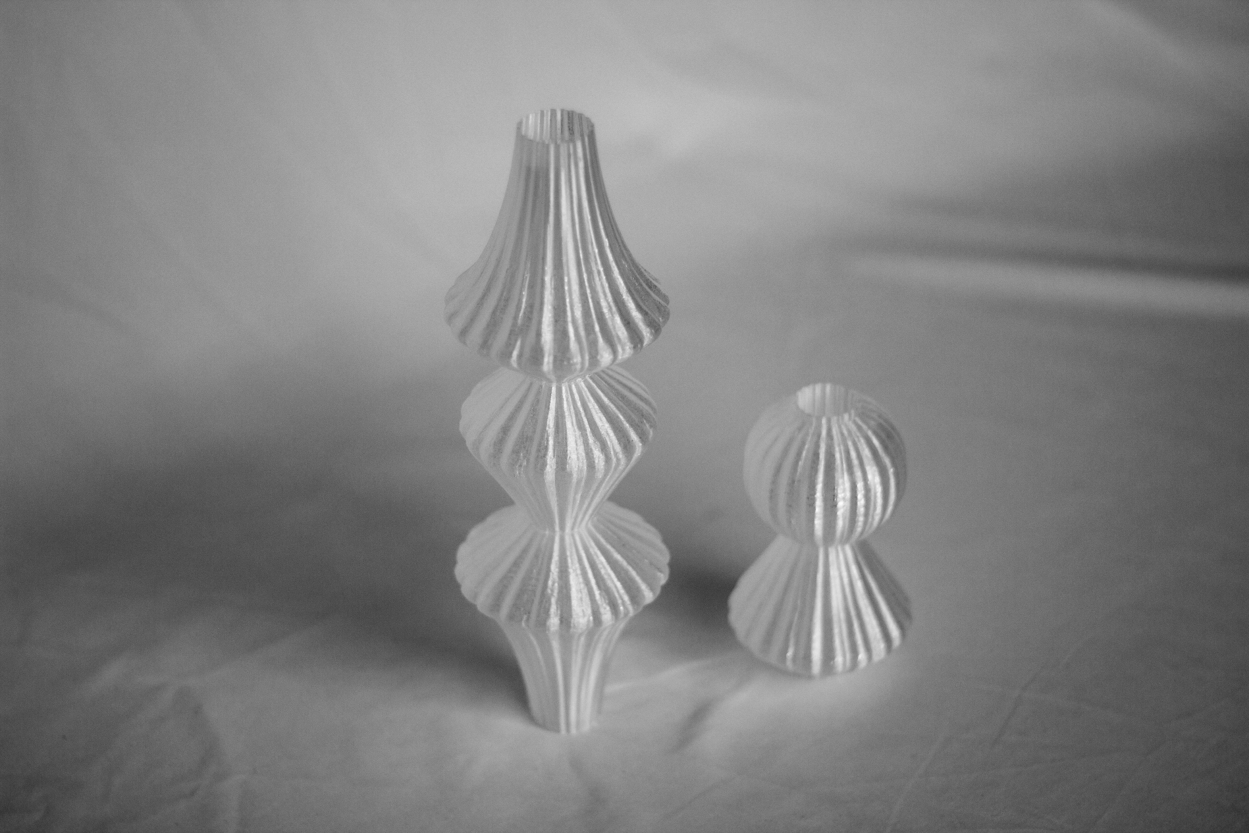
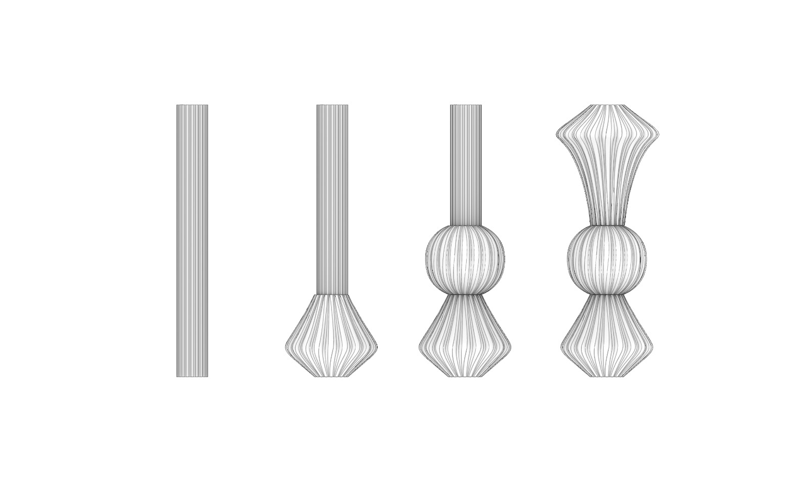
For week 4 3D printing, I tested printing shades for lights in translucent plastic. I think I might try and implement some kind of printed covering for the final, rather than just exposed fluorescent tubes. I also had the idea this week that if I use color changing LEDs in my design, I could also make the lights change colors as they rise and fall.
I tried my best to spend most project weeks working towards my final project. See inputs week, outputs week, and networks week to read more about those processes and labors.
After I got the one motor working and raising and lowering a light tube (weeks after outputs week was supposed to finish), I had to have a very real conversation with myself. Did I think I would be able to do that 7 more times with the time I had left while battling 3 other finals and 2 jobs? Probably not. So I value engineered.
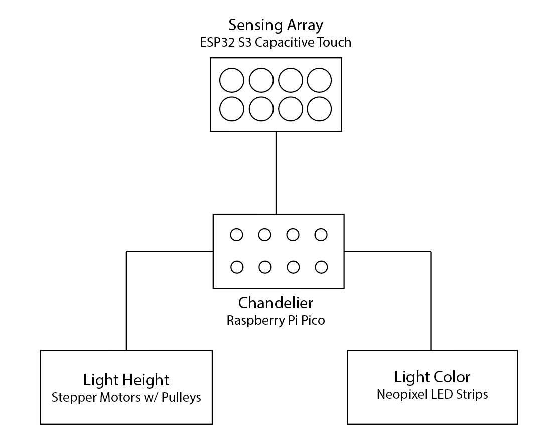
The new goal was as follows: with the same design (more or less), make a chandelier whose color changes based on a capacitive touch pad.
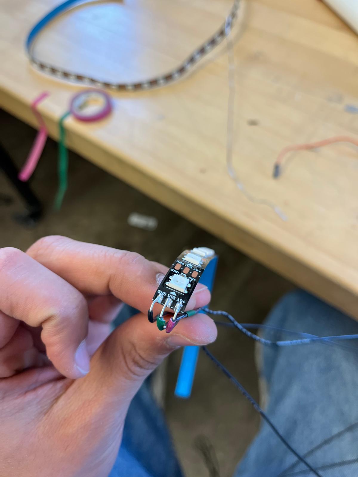
So to begin this, I started wiring my neopixels. To initially test the lights, I made a board with an RP2040 and connection for 5V, ground, and data. I milled the board, plugged it in, sent it my simple test code and… nothing.
At the same time I was attempting to mill and test another board with an ESP32S3 to test capacitive touch with a copper pad off the board itself. I soldered up that board, sent code, opened the serial plotter, and… nothing.
So with these two boards in hand, I ran down to the EECS lab for some help from my hero Anthony. He was a little pressed for time but gave me the few minutes he had. We sat down to debug and determined it wasn’t a soldering issue for either. So must be the code? It turns out I had misnamed the pins. For the ESP32, the pins prefer to be named with just their number, and for the RP2040 they seem to prefer D and then their number. Who knows why but that has worked for me since. With LEDs lit and capacitive touch sensing, I was ready to head back to integrate. See more on integration week about the process there.
After a conversation with Diana and Anthony, I realized I might not actually even need two boards. In theory I could wire the neopixels in series and only need 1 pin to address them. That means that with the capacitive touch already embedded with the ESP32S3, I would have enough pins to run everything. So that was the plan.
I put a pause on electronics and focused in on my hardware design. In Rhino I modeled the entire system. In the design, I modeled as if I were including motors, in case I decide to add them later with more time.
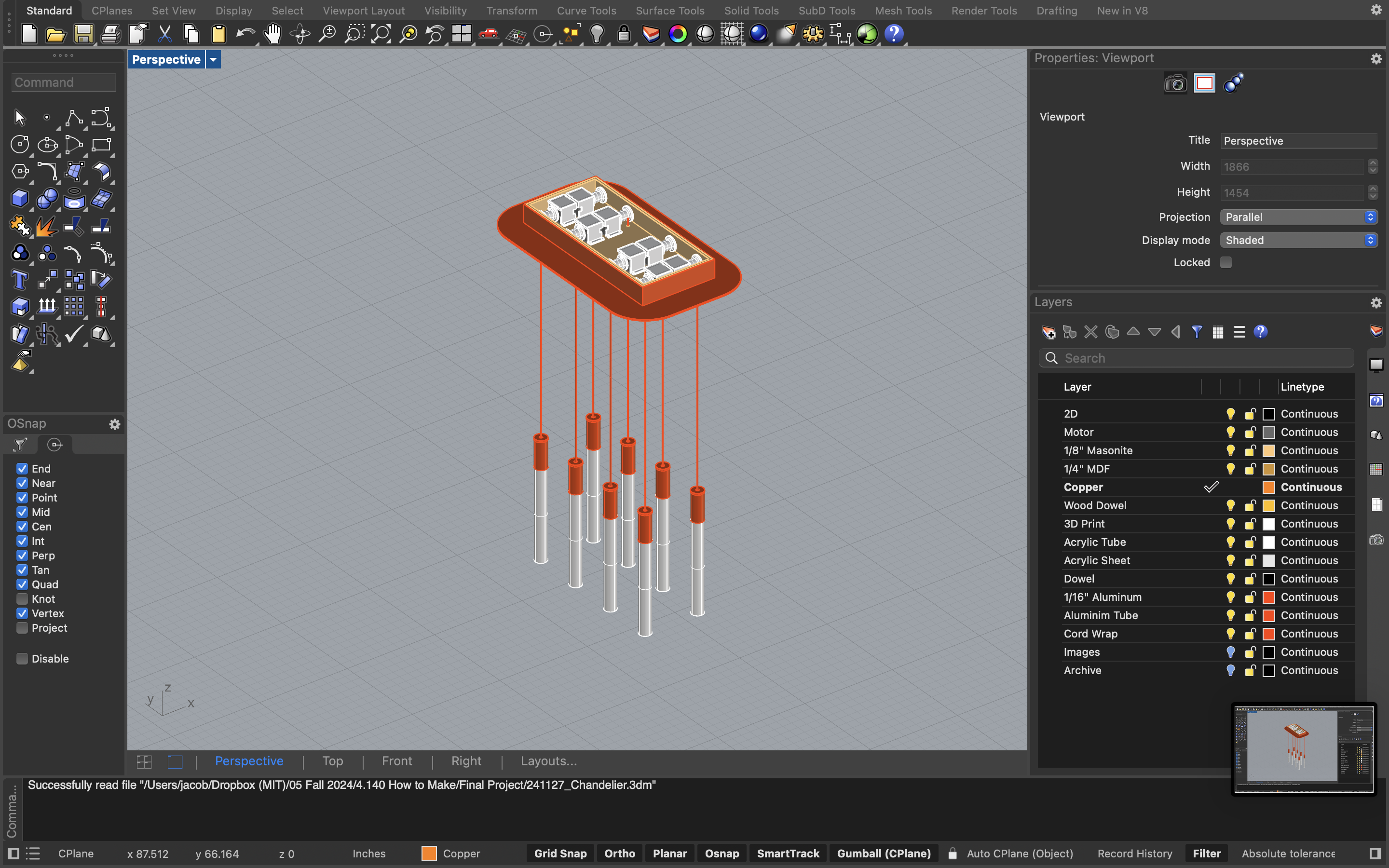
The lights consisted of neopixels wrapped around a wooden dowel. The dowel inserts into a 3D printed coupler that also holds an aluminum tube and a frosted acrylic tube. The wires for the neopixels channel up through the coupler and into a cable sleeve. They then travel into the upper housing which is a masonite box with aluminum surrounding.
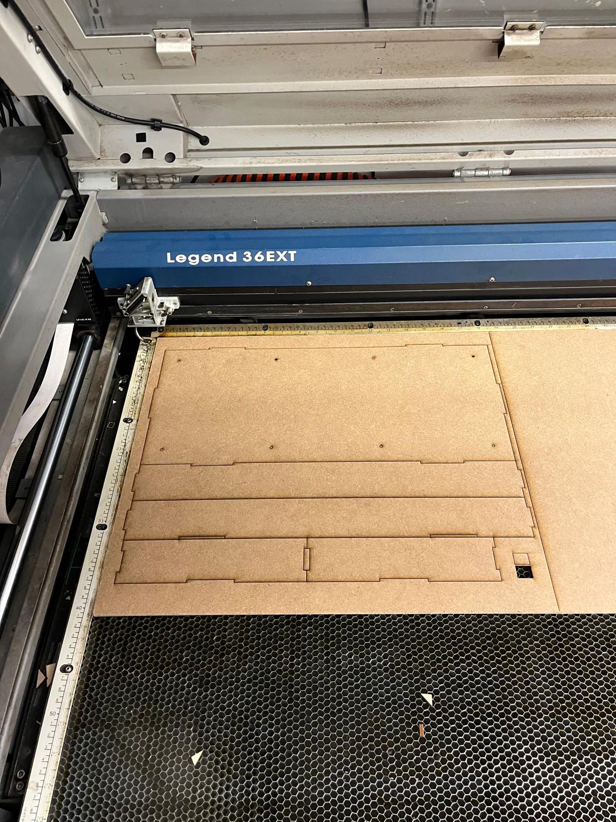
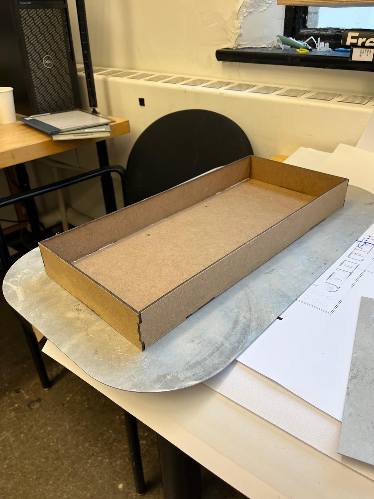
To assemble this all, I began by laser cutting the masonite and assembling those with finger joints and glue.
I also 3D printed the couplers and did a few test fits.
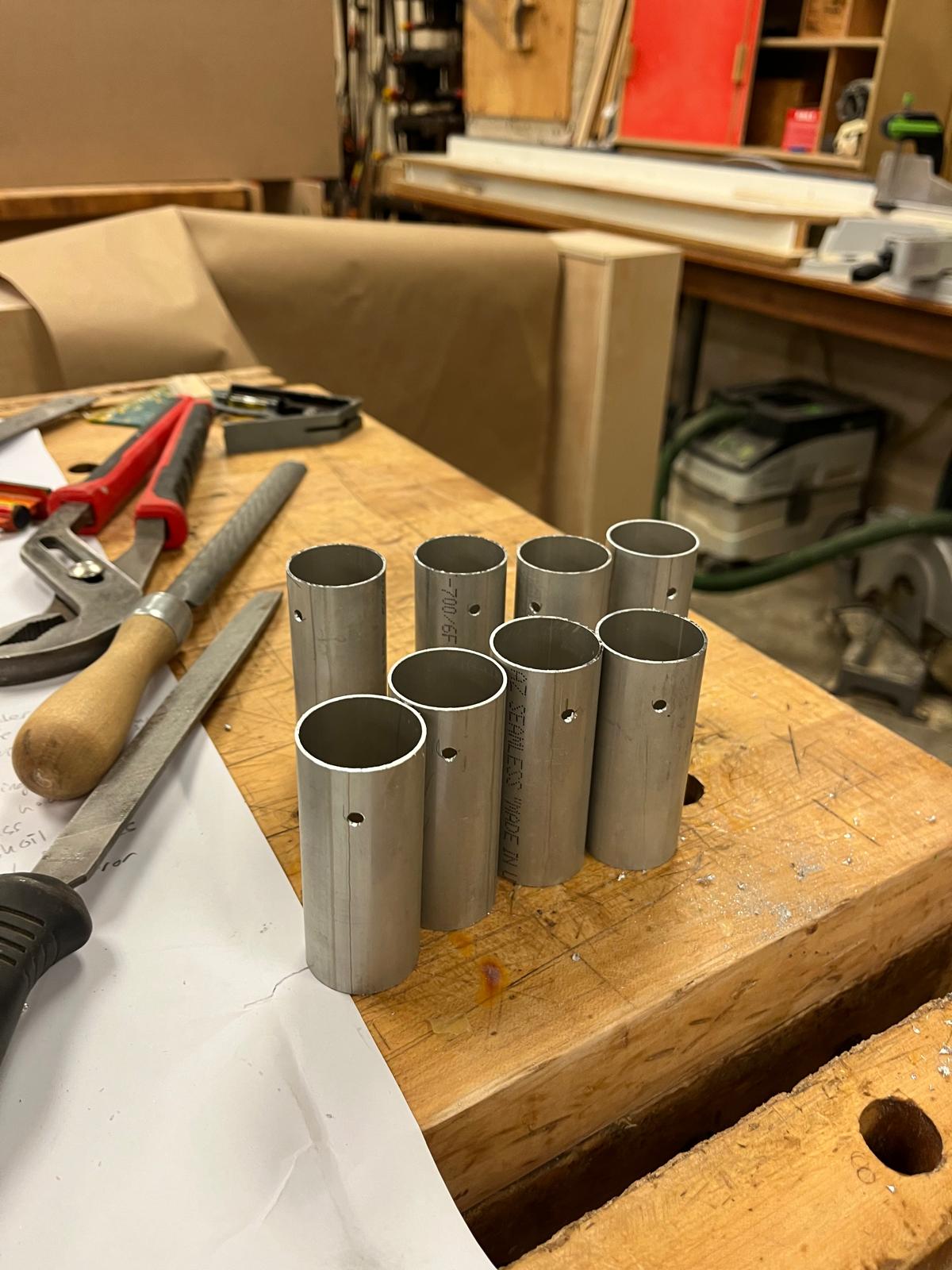
I cut the aluminum tube into 3” chunks and drilled a hole for a single screw.
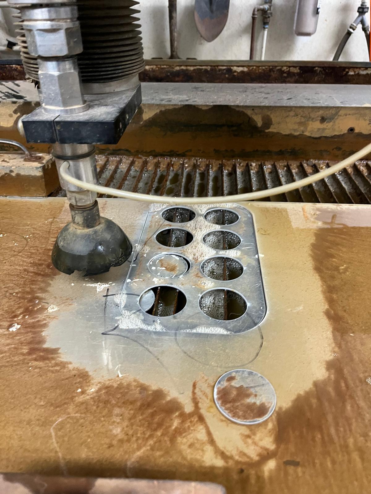
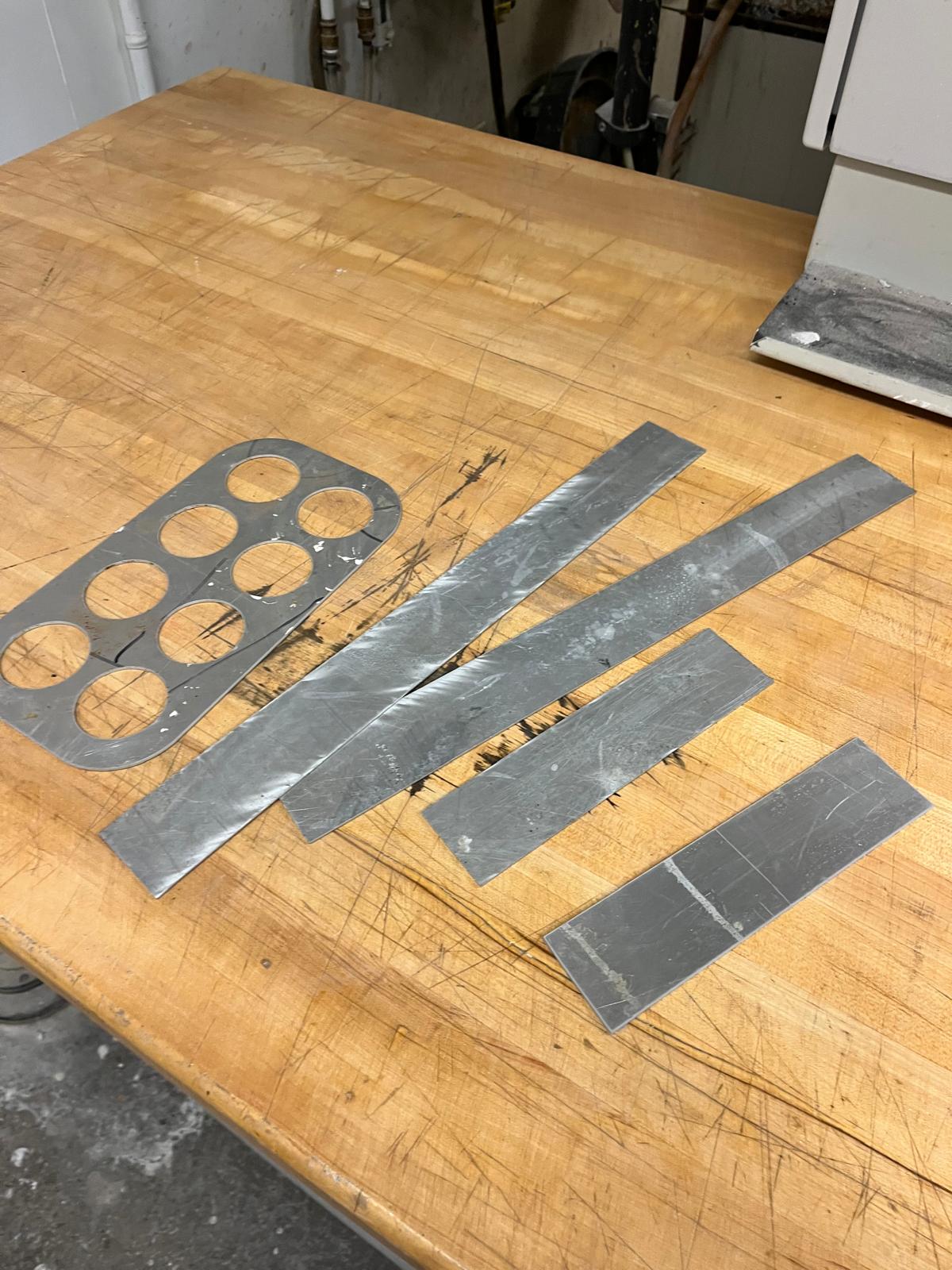
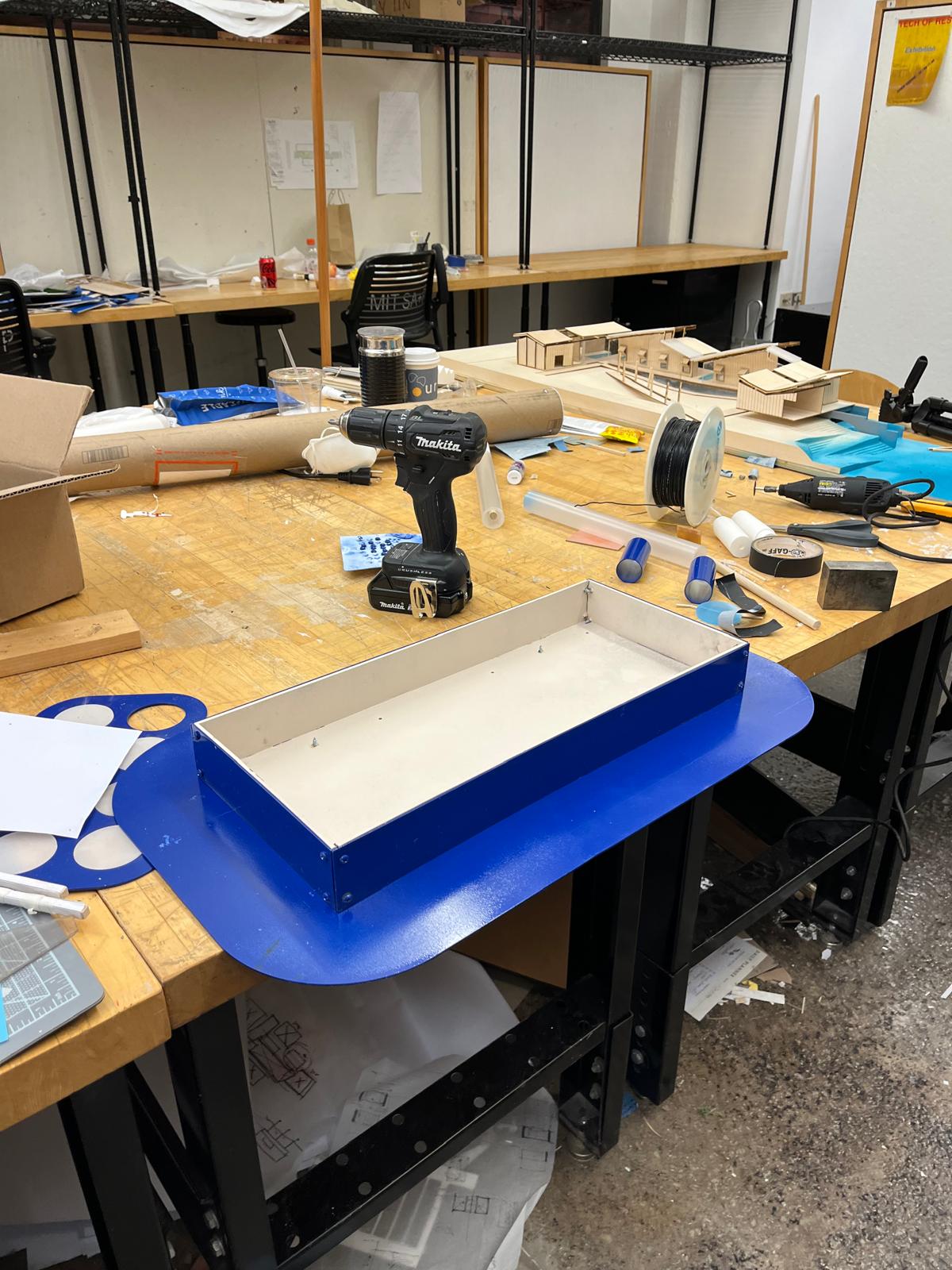
I water jet the aluminum sheet in the architecture shops to create the pieces for both the chandelier and also the controller component. Which was designed as a piece with holes for the copper pads and space to cover with frosted acrylic for the aesthetic.
I laser cut acrylic for the sensing pads and also to raise the aluminum off of the copper pads.
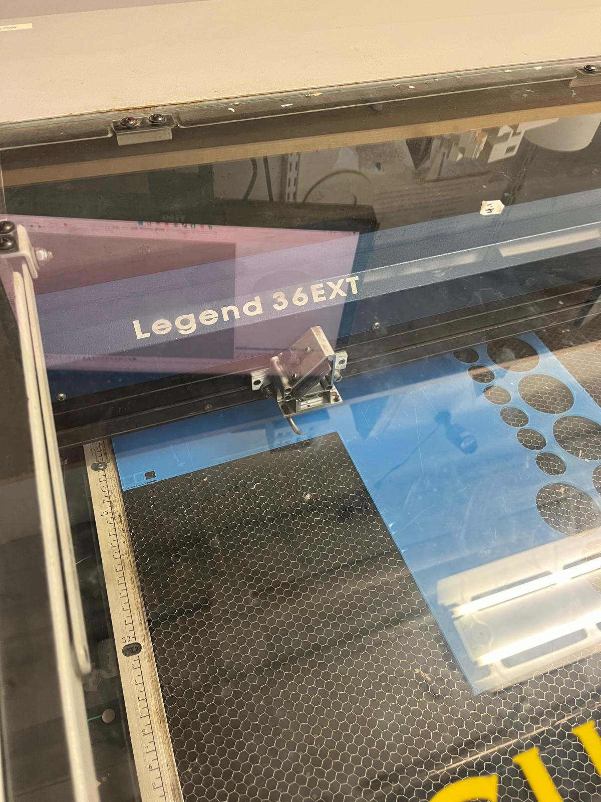
I frosted the acrylic that was meant to cover the sensing pads using the sand blaster to conceal the copper.
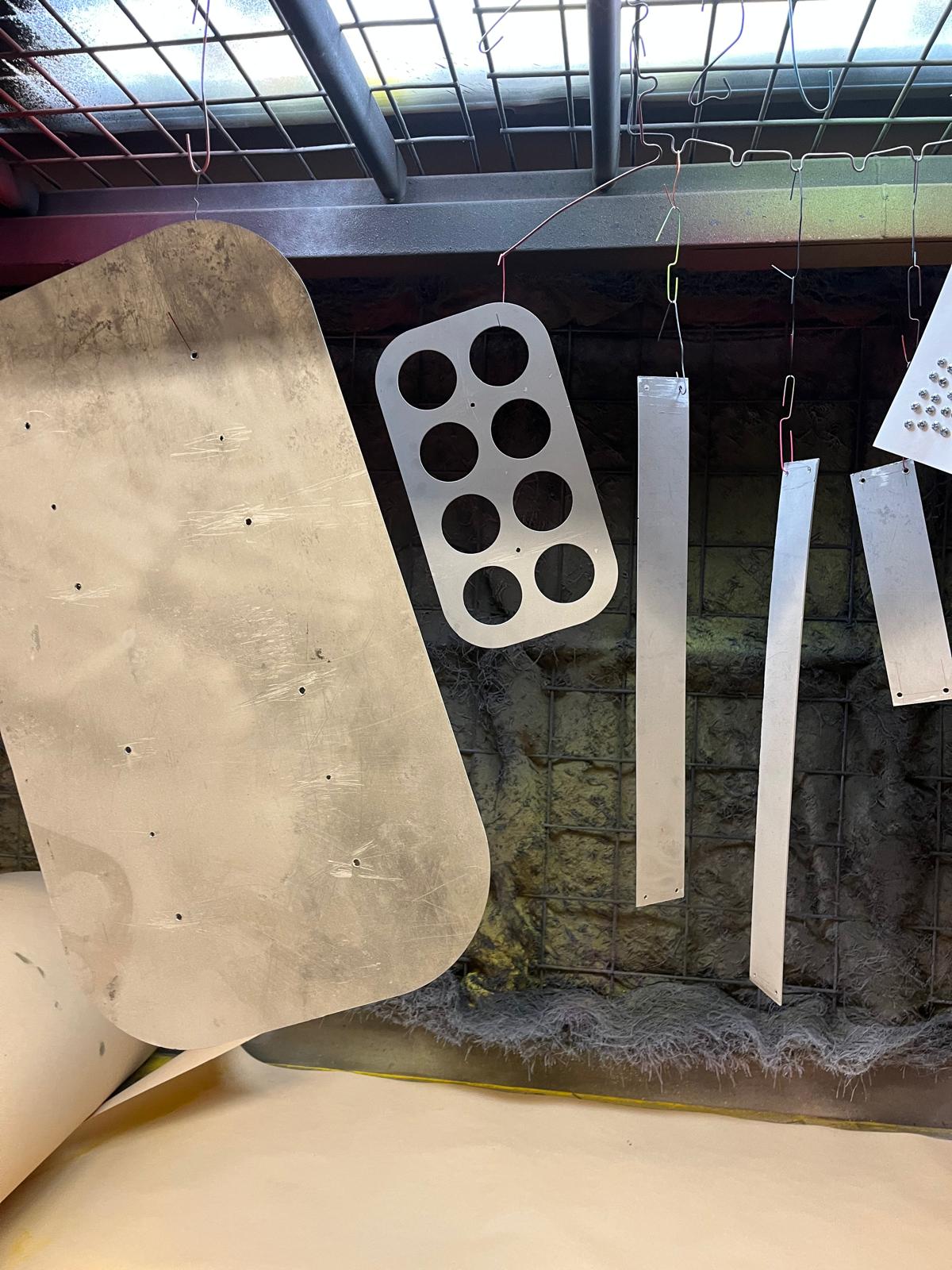
Then time to powder coat. I went over to N52 and got taught how to do that process by Bill McKenna - the shop manager. I picked out a blue that I like and sprayed all of my pieces while they were connected to an electrode. Then I baked them in the oven at 400 degrees for 10 minutes per the specification of the powder. I made sure to do some screw heads too! Gotta be thorough.
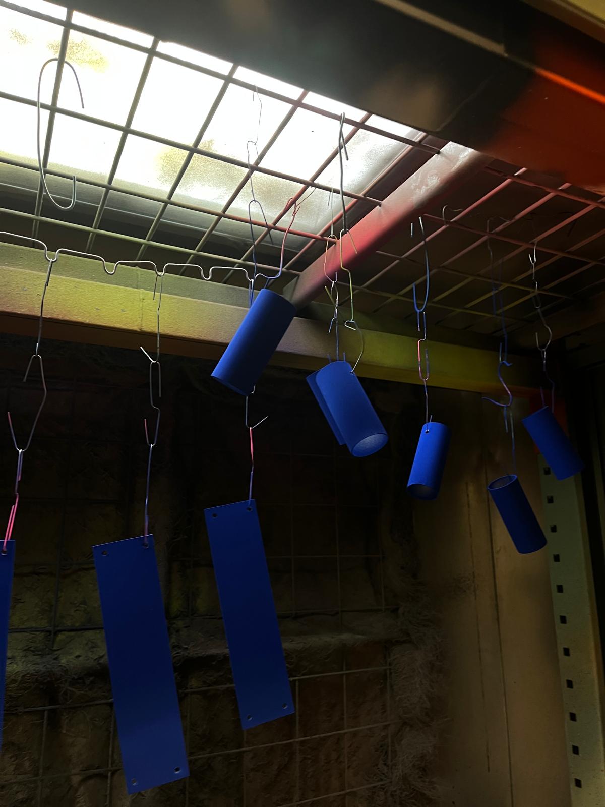
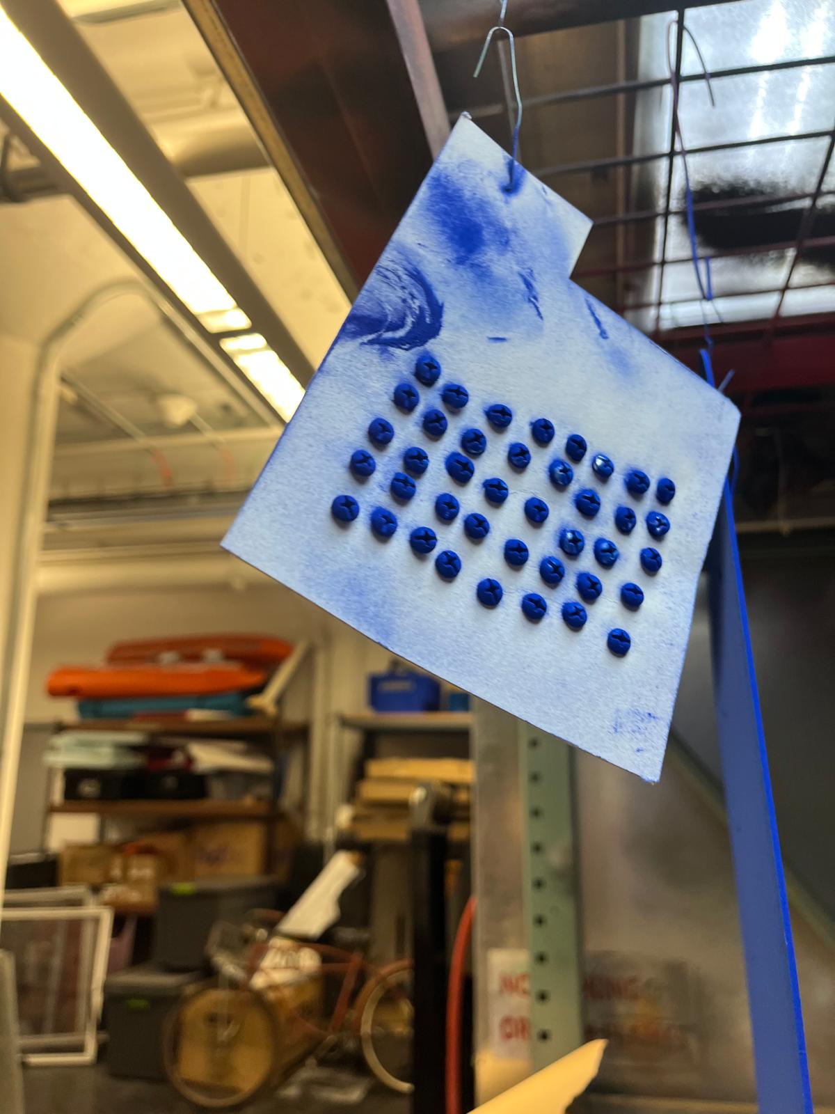
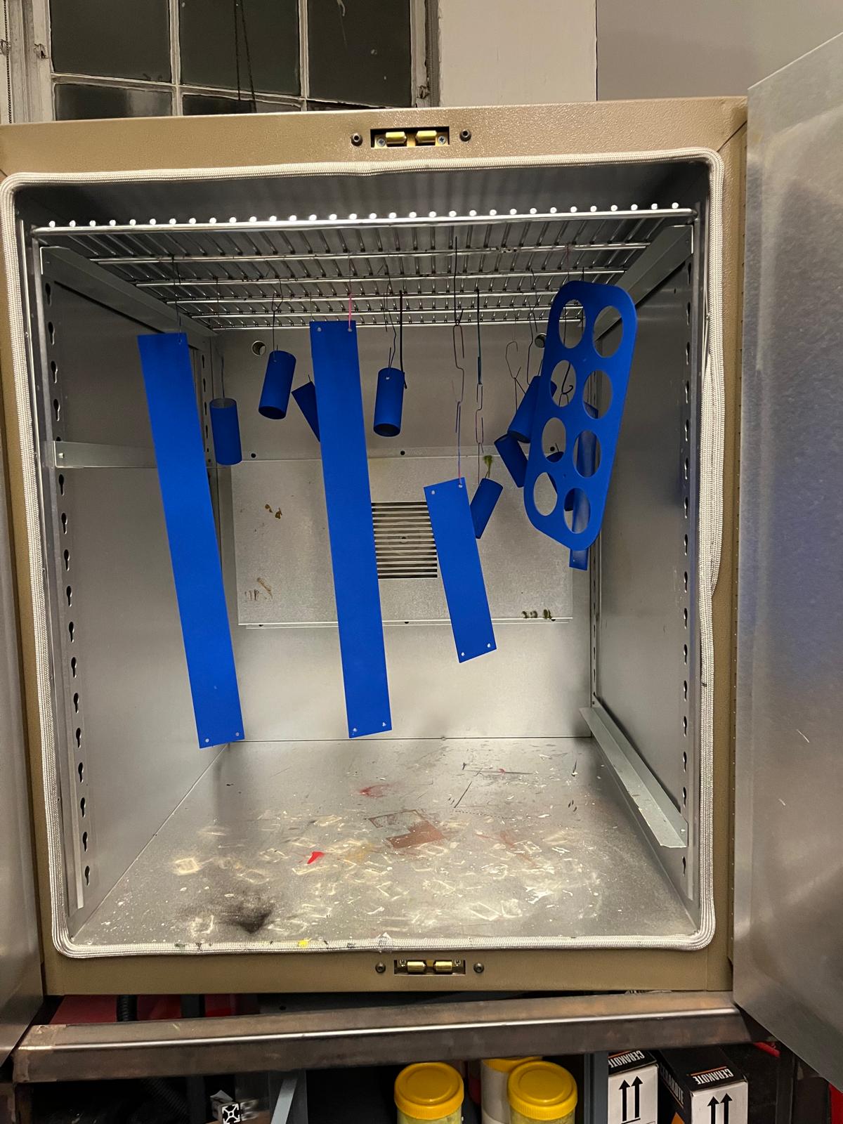
Took the pieces out of the oven and they came out great.
I assembled these pieces, screwing things together and they fit nicely. I had to pre-drill holes to prevent splitting the Masonite.
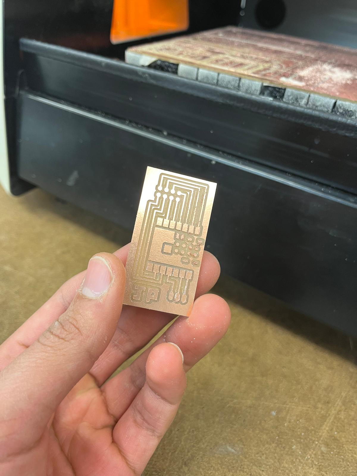
Then it was time to design my final PCB. The design was fairly straightforward. An ESP32S3, 8 pin connector out for capacitive touch, and 3 pins out for the LEDs. I threw my initials in there for good measure and milled and soldered the board.
Next up was some more LED testing for the light units. I had to make sure I could power all the lights I needed off of one 5V input so I slowly called more and more lights off of the RP2040 board until I got to 600. There was a little bit of brightness falloff but they worked!
The diffusion looked great behind the acrylic tube. Here is a small test.
Then it was time to start to wire things up. I cut the first strip on neopixels (75) and connected the three wires (power, ground, and data). I’m grateful this soldering was so straightforward because I knew I was about to do it so many times. I added wires to both ends of the strip so that I could string to the next set of neopixels as well. Then I wrapped the neopixels around a wooden dowel and assembled the first unit. I powered up the lights and was very disappointed with what I saw. The diffusion was working great because the LEDs were too close to the acrylic meaning the light didn’t have enough room to disperse. So I made the executive decision to remove the dowels and instead have one strip of LEDs taped to the back of the acrylic tube to maximize light dispersion. I was much more satisfied with this result and continued with that design change.
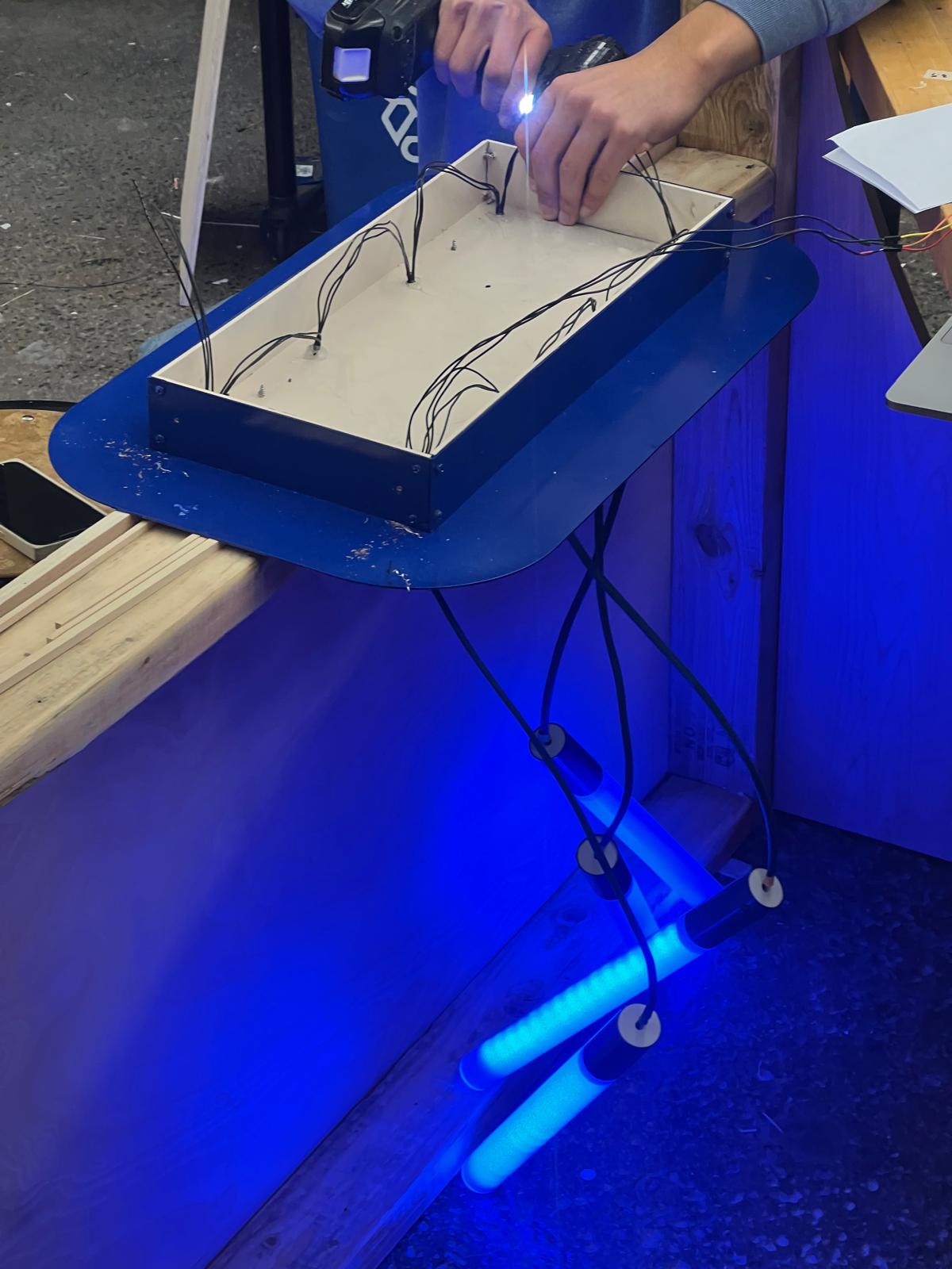
This next part ended up being a little bit of a nightmare. The only wire we had access to in the arch shops that was available in the quantities I needed was solid strand black wire. But I needed to keep track of 3 different cords for every light. So instead I used colored tape to mark the ends of each individual wire. Not the right choice. I should’ve hunted down different colors.
But I persisted, and slowly the lights started coming together. I powered them up with every new light added. Eventually 1 became 8.
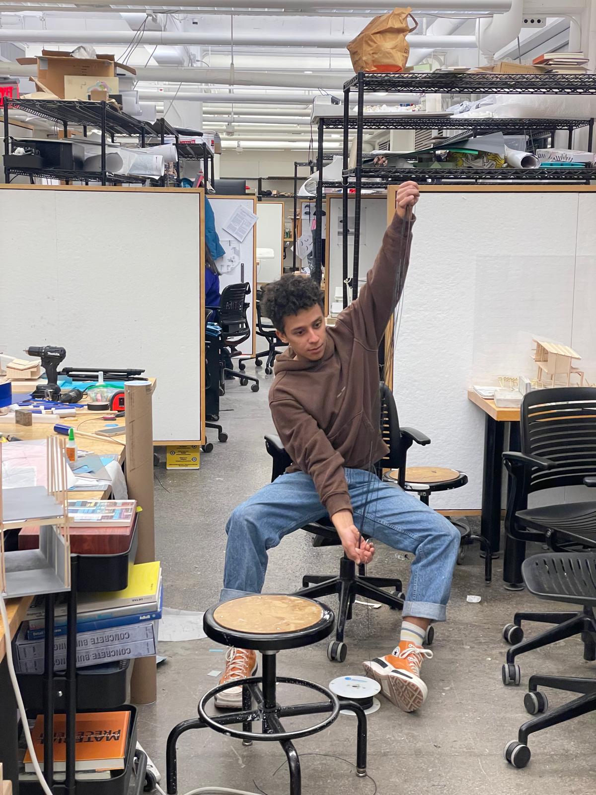
It was also sometime around this point that I was realizing I would need something to hang my chandelier from. I was worried hanging from the Media Lab ceiling would present a significant logistical challenge that I wanted to avoid. So I figured why not make my own frame. During my shop shift at N51 I found some scrap plywood and some pretty crappy 2x4’s and gave myself and my partner in crime Sloan Aulgur two hours to throw this thing together or forget about it. But we pulled it off and the frame came out great. 6 feet tall and 4 feet wide.
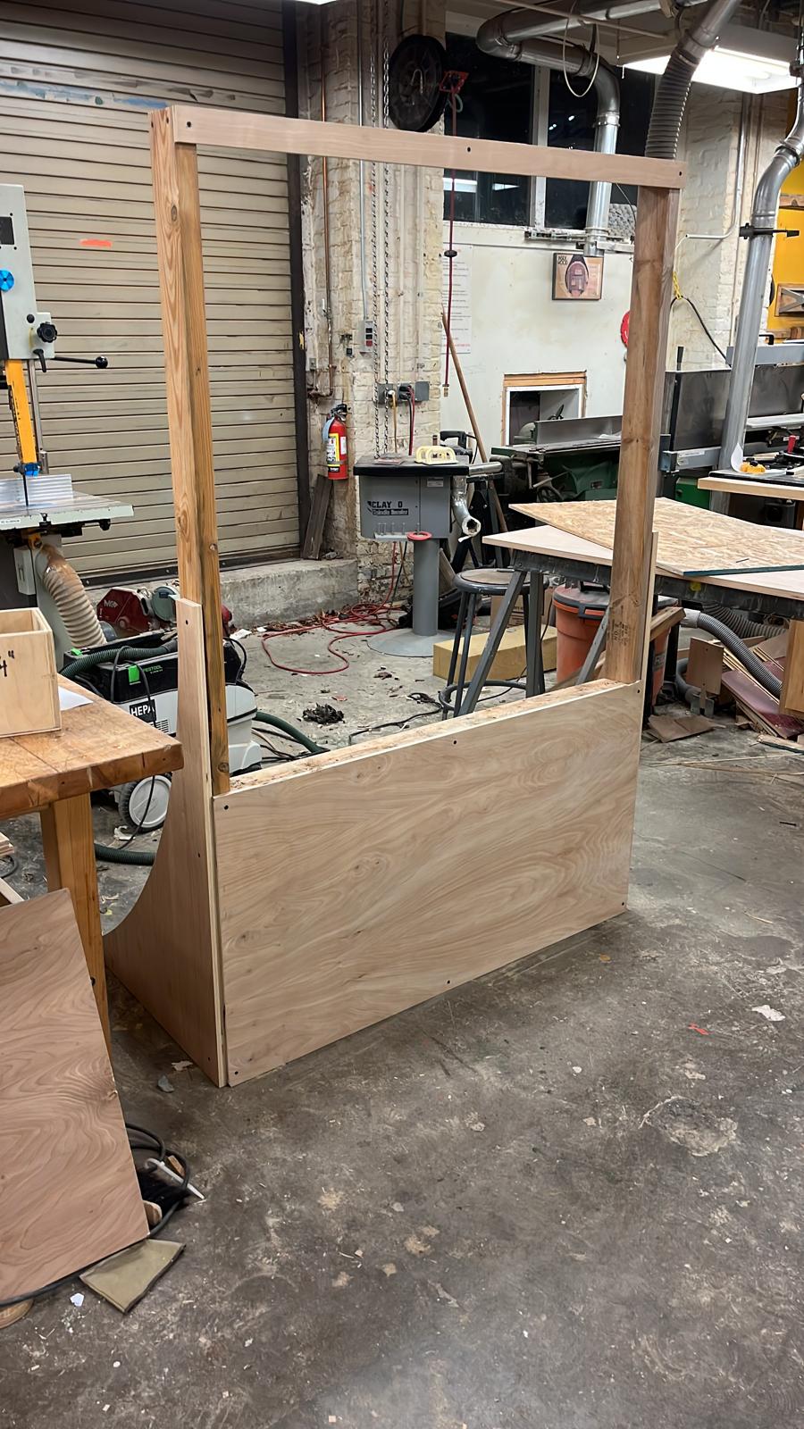
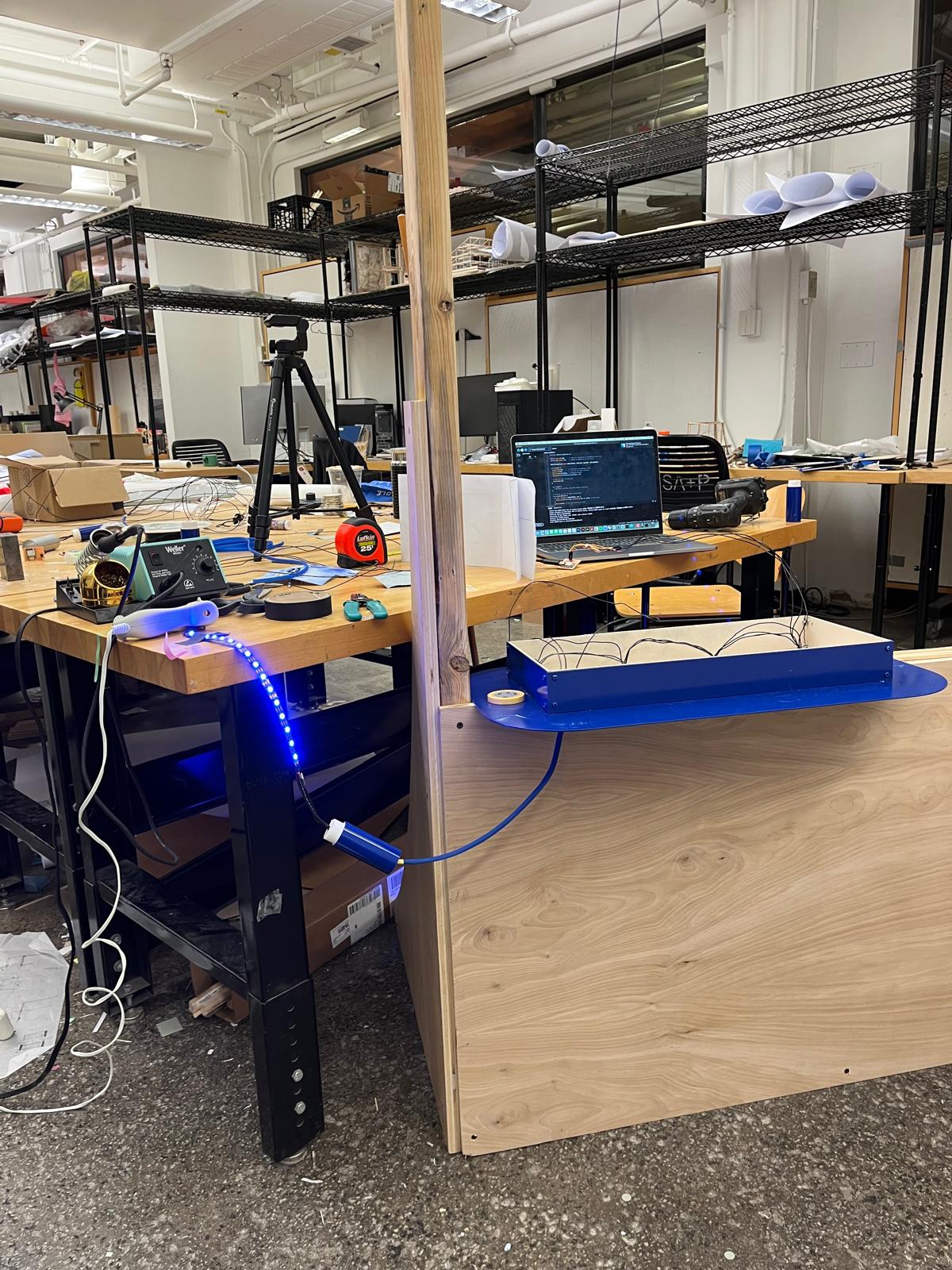
We brought it back to studio and hung up my chandelier.
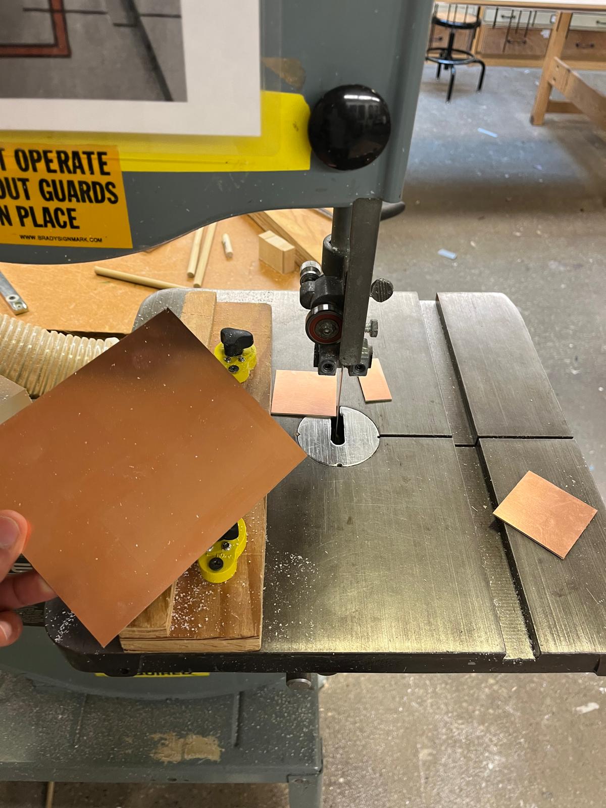
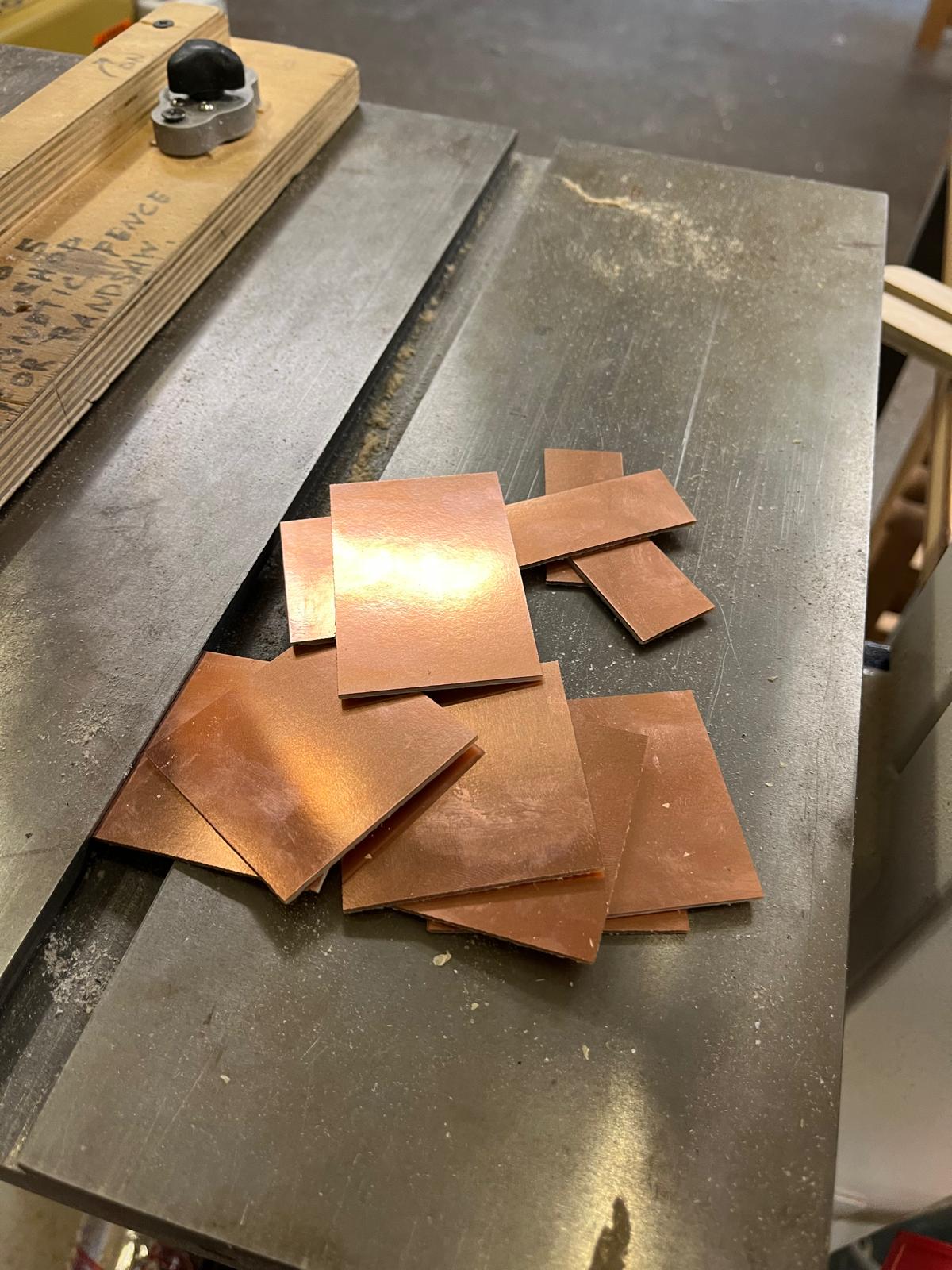
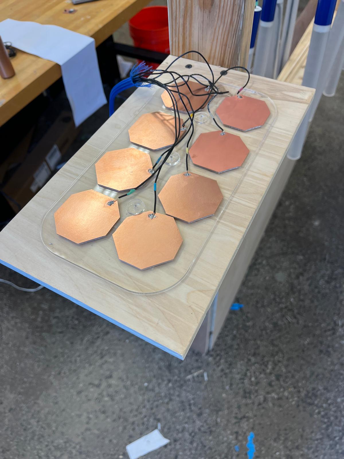
Now for the touch pad. I cut copper for the touch sensors on the band saw and wired them up to a set of 8 cables that plugged into my board. I hot glued them down to the board and organized the cables to the best of my ability. I ran some tests with them and I could address each of them individually and get a solid reading using the serial plotter to verify. I assumed the finish line was in sight here. But it was not.
I plugged the neopixels into my board and tried to run some test code with them all controlling a different light. But that did not work. After several rounds of code edits I encountered several errors. Sometimes all the lights would turn on and stay on. Sometimes no lights would turn on. Sometimes lights would flash when they weren’t supposed to. I spent hours fighting against the capacitive touch relative thresholds and deltas with no luck. The best that I got was with touchpad 1 controlling all 8 lights, turning them on and off with a touch. I was never able to get two working in the same code.
It was here that I started having ESP32 issues. I’m not sure what causes this but I know several classmates were having issues too where after a few attempts of uploading code to the microcontroller, you start encountering a fatal error. The error took forever to “solve”. And the only solution I found after a visit from Jake was to put the board into boot loader and reset it by pressing a combination of the two buttons on the board before plugging it in, while plugging it in, and after it’s plugged in. I’m not sure which the correct order is but every once in a while it would reset and I could send new code to test. The Internet didn’t have a clear answer on how to do this correctly. So this severely slowed down my ability to debug.

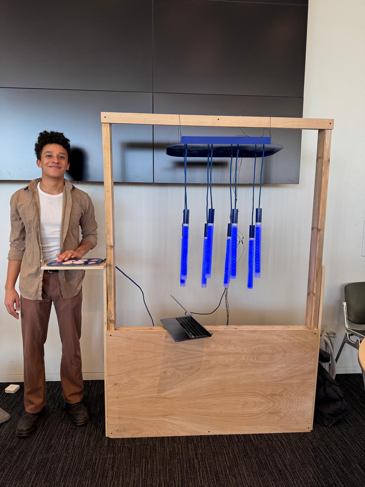
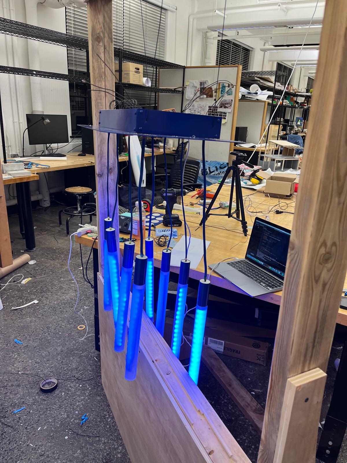
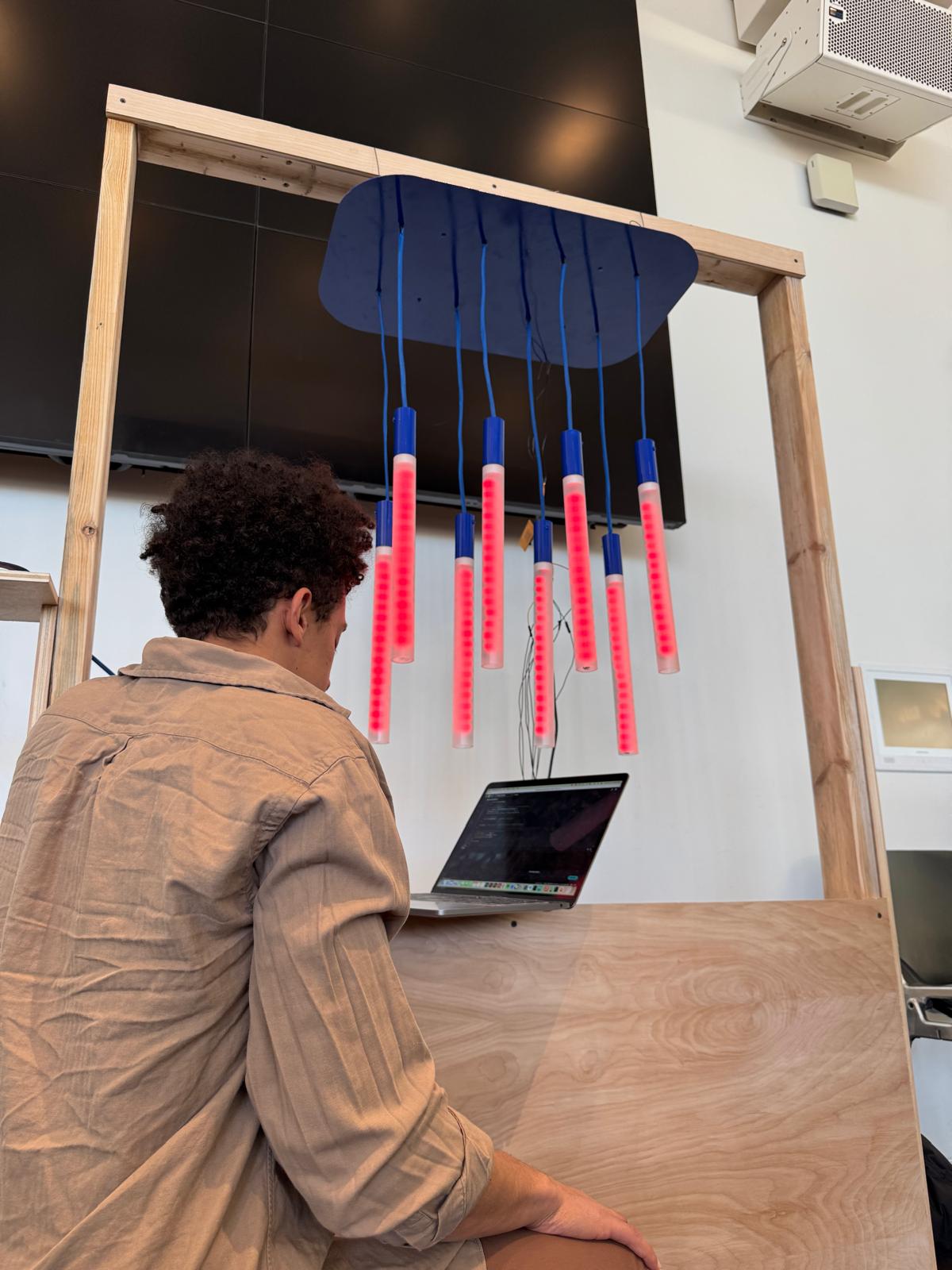
For the final review, I did a demo that included some of the potential patterns that I would like users to be able to play with once the capacitive touch is fully integrated. I also spent some time at the final review doing more debugging and was able to reset things to the state where you could press touch pad one and control the lights turning on and off again for demonstration purposes.
I’m excited to continue working on this project in my free time to get things up and running at full capacity to maybe install it in my apartment someday. But for now, I’m proud that I made at least the bare minimum happen harkening all the way back to my first inputs week - I made a light blink with touch of a button - this time it’s just a little bit more sophisticated. And I’ll take that as a win.
Thank you to Neil for all the work he puts into this course every year. And thank you to the class staff for all their constant support and debugging. And thank you to all of my friends in the architecture section - I couldn’t have asked for a better team to do this all with.
We made it.
- Jacob