This week started off pretty daunting for me. My electronics experience thus far has been incredibly limited. After attending the recitation for the week, I weighed my options between beginning my PCB design in KiCAD or Fusion 360. Since the Fusion interface is already more or less familiar to me, I decided to move forward with that.
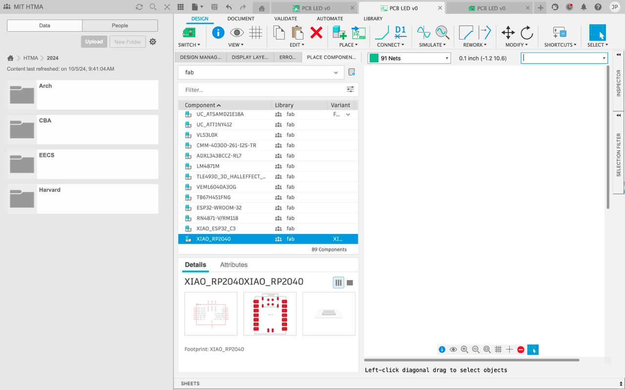
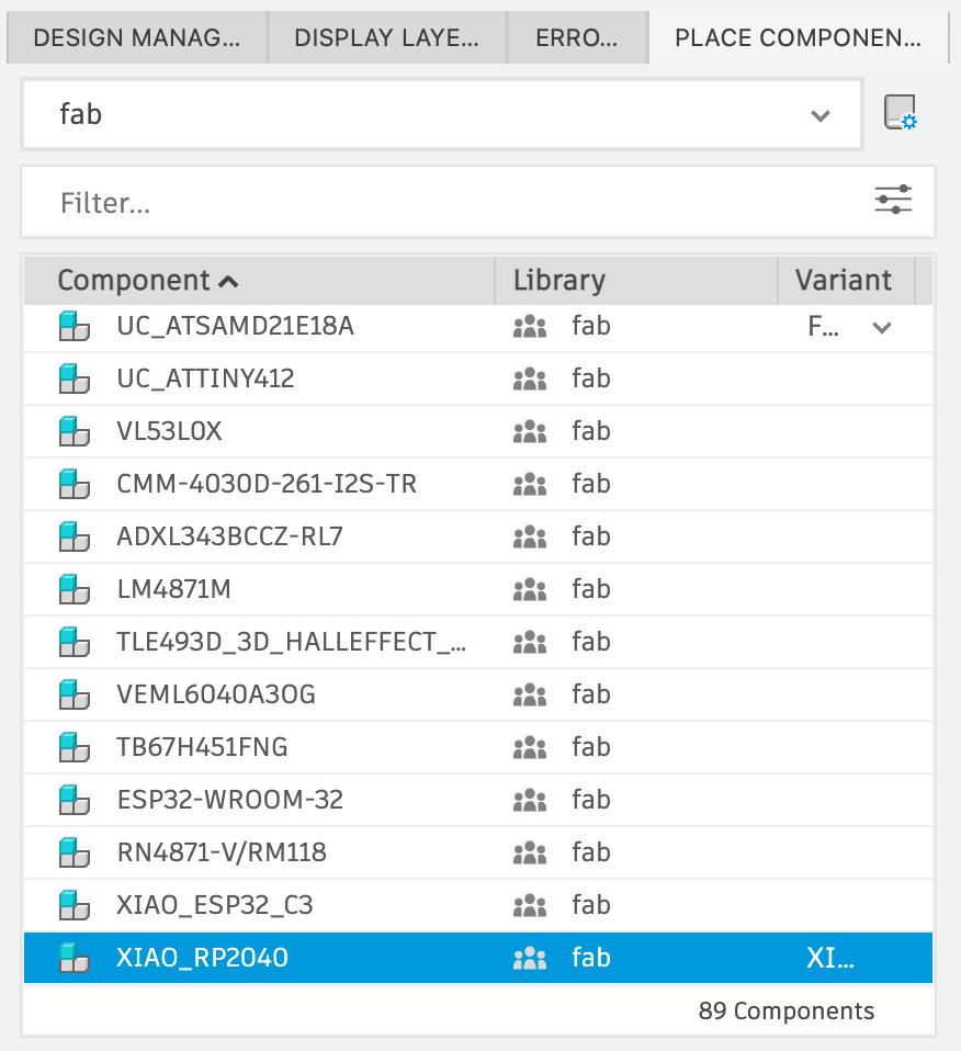
After joining the class team on Fusion, I added the fab library and began messing around looking through components. That was about as far as I got before realizing I would need help in office hours to continue any further.
I went to the CBA weekly office hours and talked to a few TA's to get help on designing my PCB. I began by walking them through my final project idea to see if I might try and test a motor and sensor this week. They advised me that it would probably be best to this week just plan on doing something simpler like controlling an LED with a button to start - so that's what I did.
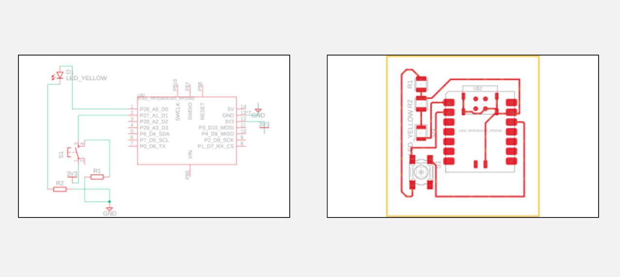
My board design uses a XIAO RP2040 microcontroller, an LED, and a button - pretty straightforward, but still required a lot of assistance since this is my first time. The LED is connected to a pin of the XIAO and a resistor, which then connects to ground. The button is connected to power, a pin, and a resistor.
After making the connections in the design document in fusion, I switched over to the PCB design page, changed the design rules to account for the 16mm size of the endmill we will be using, and connected the components on the board such that no lines intersect and the overall board size is not too big.
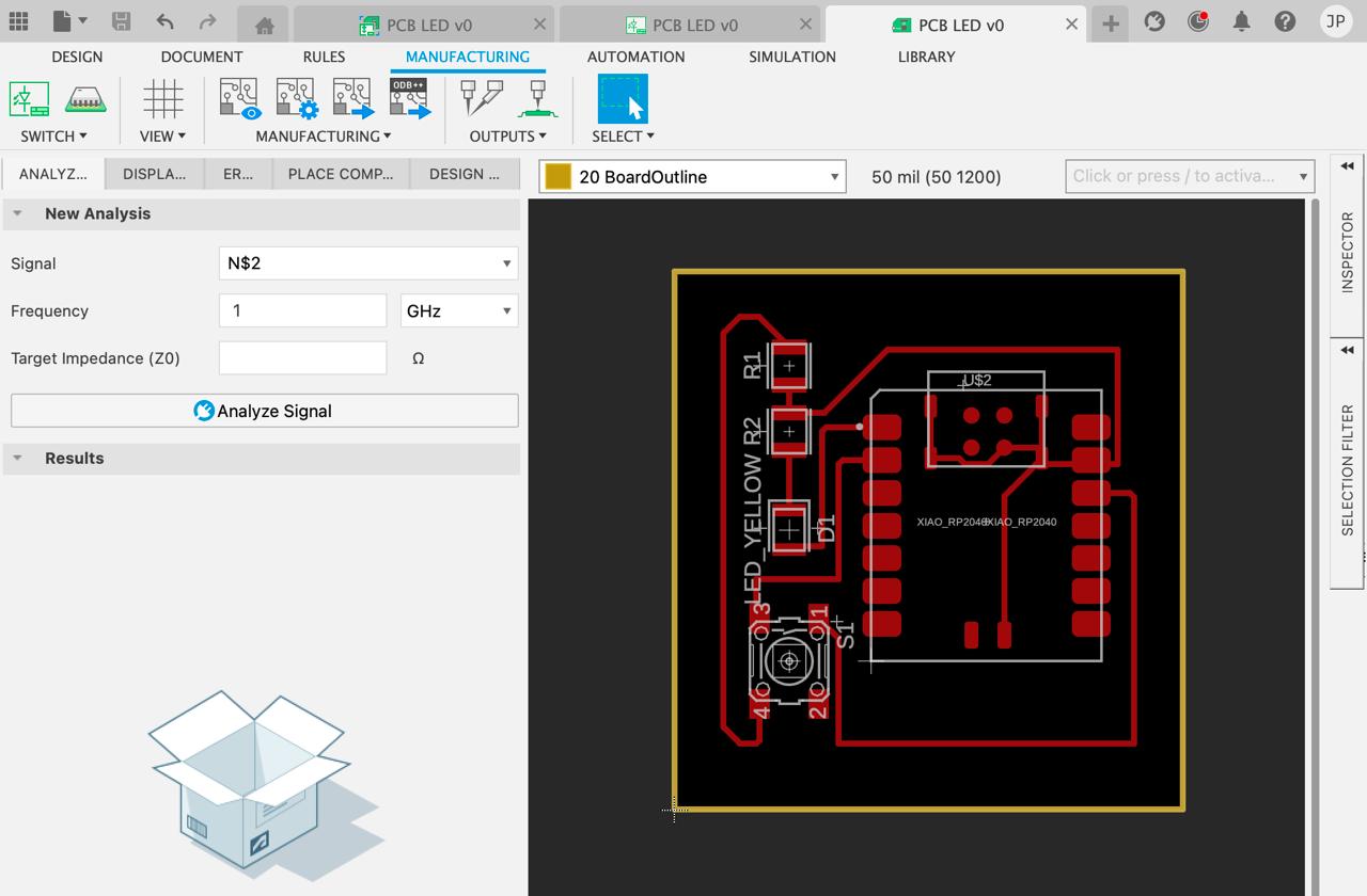
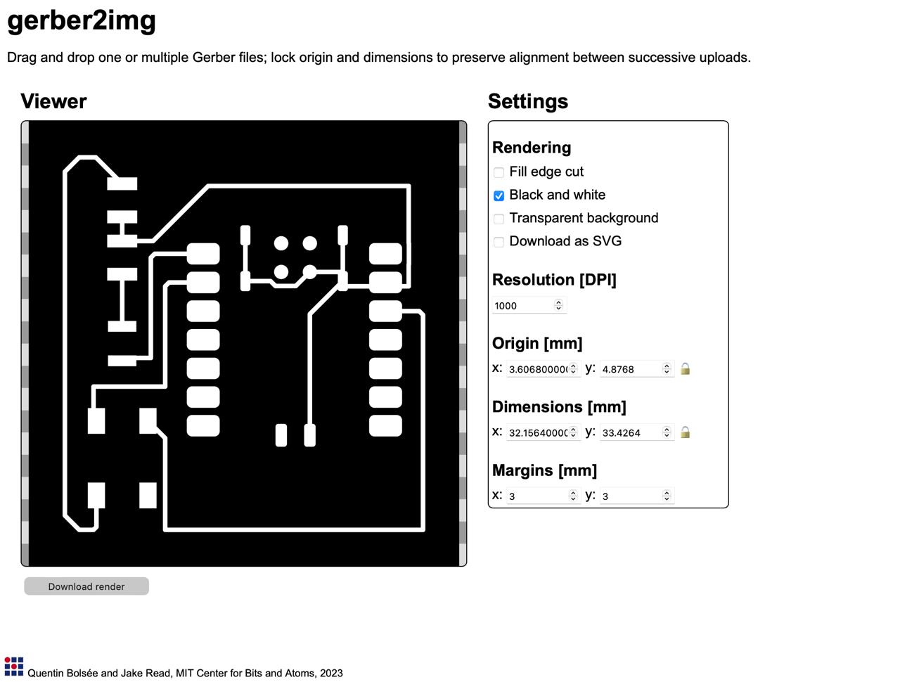
From there, I exported the gerber file and converted it to a png with Quentin's gerber2img program. The finished board is below and should be ready to mill!