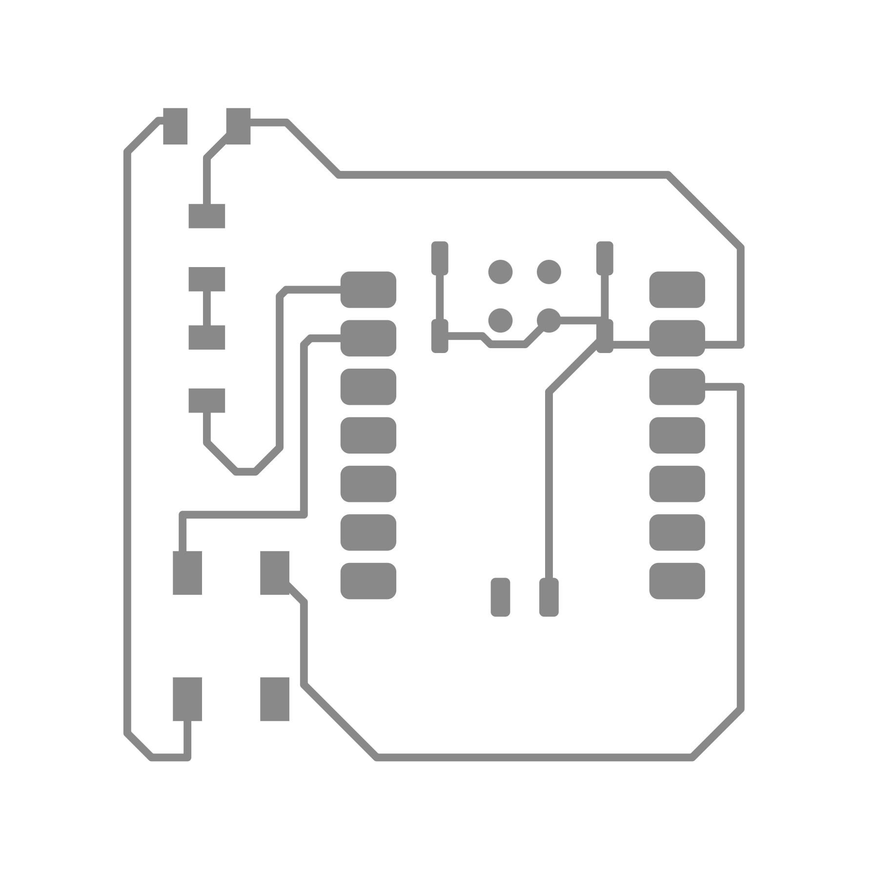
After presenting my website in class last week, I learned that I had used the wrong footprints for the LEDs and resistors in my PCB design. So I went back into Fusion to update with the correct components from the Fab library. I exported this new gerber file and created the PNG below.
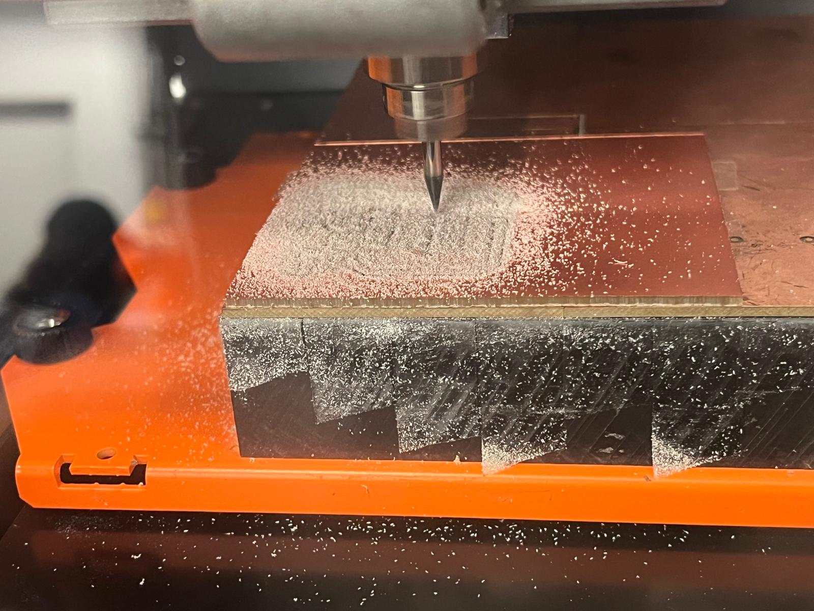
I took my PNG design into mods in the architecture shop on the computer attached to the Roland. I got all set up and milled the trace layer using the 1/64 endmill. This pass went fine on the first try. But then when I went to run the outline pass with the 1/32 endmill, I noticed that the alignment looked incorrect. I stopped the machine and took out my board and I was correct - it was no longer aligned.
I realized that the alignment error must have occurred when converting the gerber files to PNGs. I went back to gerber2img and found that I need to be locking the origin and dimensions after dropping in the outline file, before adding in the trace file. So I did these steps this time around and re-exported new PNGs.
I milled the board again, this time with success!
Then I grabbed all the components I would need and started soldering the board. I have some basic expereince in soldering, so while this was difficult for me, I was able to get it done in a reasonable amount of time.
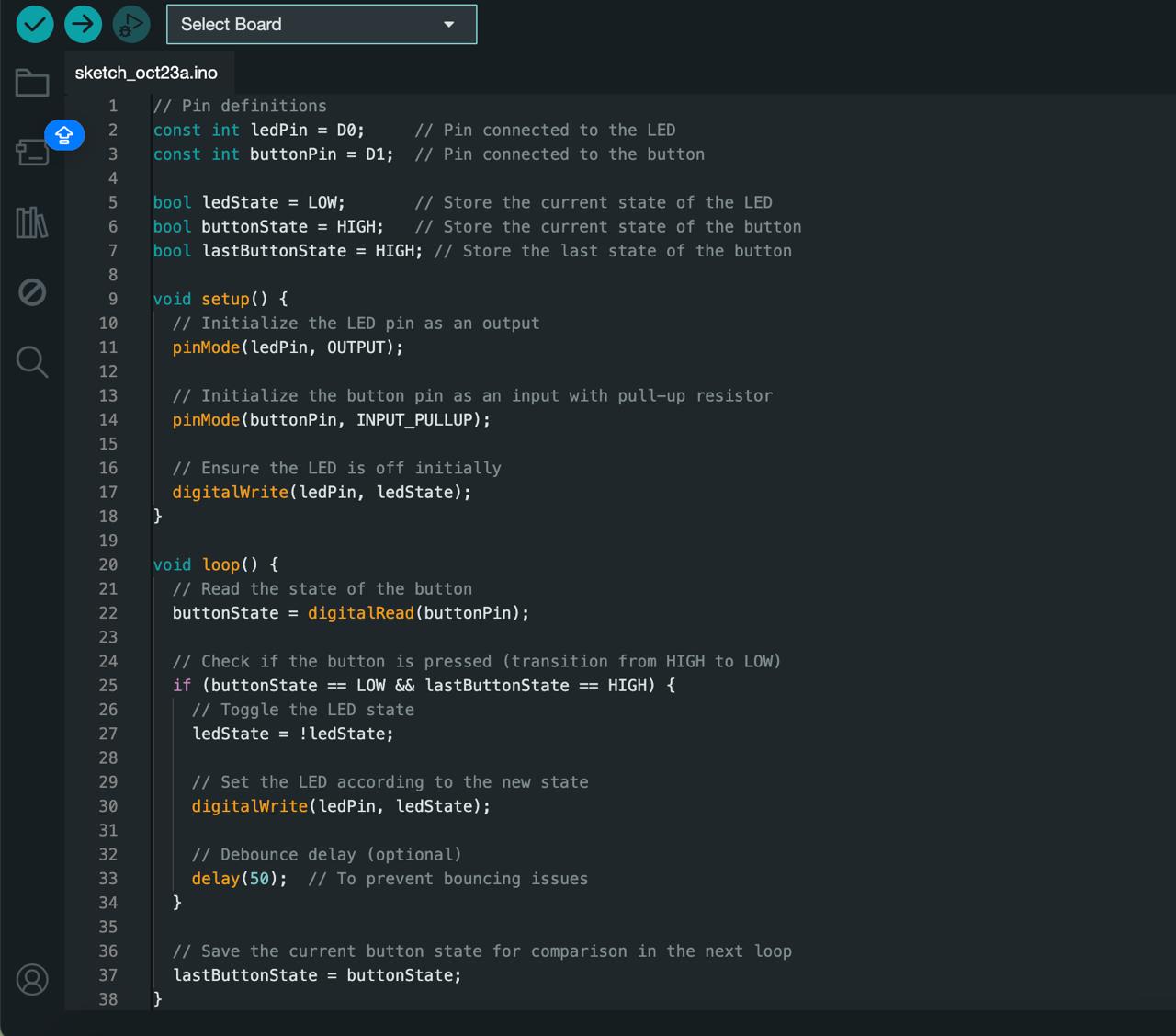
Then I connected my board to my laptop and got set up in the Arduino software. I asked chatgpt to write code for me that would allow me to control my LED with the button. I made a few small changes to the code and pushed it to my board. And it worked!