Final_project - Thu, Feb 28, 2019
JD Hagood's Final Project: Game of 15
Inspiration
For my final project, I want to make a device that times how fast you can solve a puzzle to encourage some fun competition amongst MIT puzzle nerds. During an 18.701 lecture, the professor used the Game of 15 puzzle as an example to discuss the parody of permutations. For those who are not familiar, the Game of 15 is a slider puzzle played on a 4x4 grid with numbered slider tiles. The goal is to slide around the tiles until all the pieces are in order. It is essentially a 2D rubix cube.
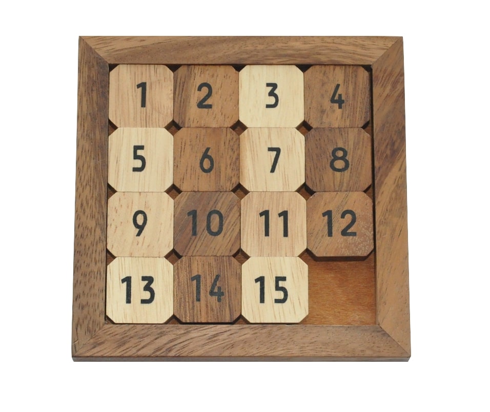
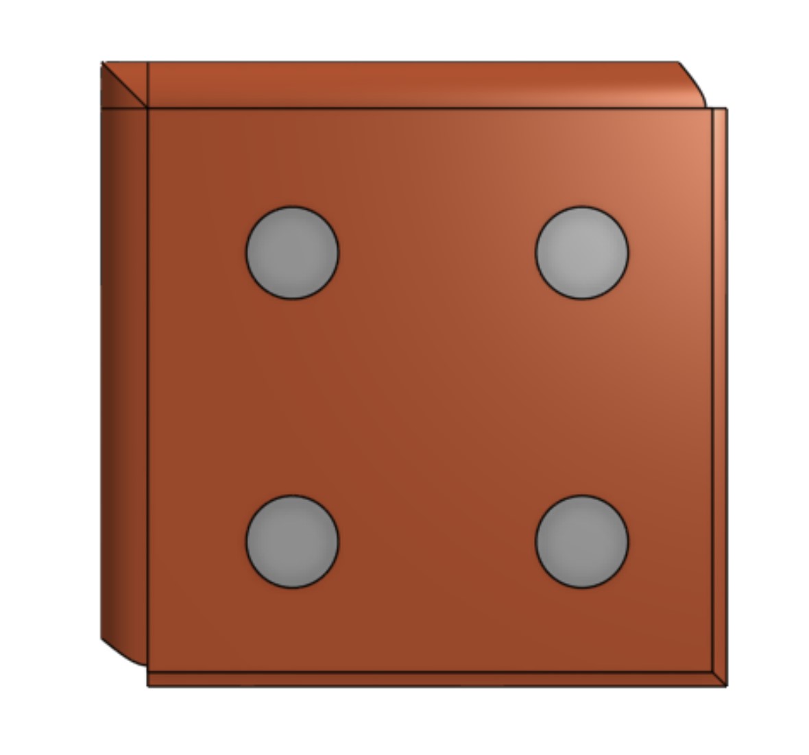
I was immediately inspired from this lecture to try to create my own 3D printable version, but with a twist. I wanted the puzzle to know when it was in the solved state and reward the solver. I therefore needed a way to electronically detect the state of the puzzle. While a camera module and a raspberry pi running a vision model would work, I wanted to make the puzzle a cohesive unit. I decided that magnets and hall effect sensors would be my best bet. Each slider piece will have 4 magnets on the back. With 4 magnets I can encode what the piece is in binary based on how the magnets are flipped. With 4 magnets I can encode up to 16 pieces which is perfect for my application. Below is how I planned to place the magnets.
CAD Design
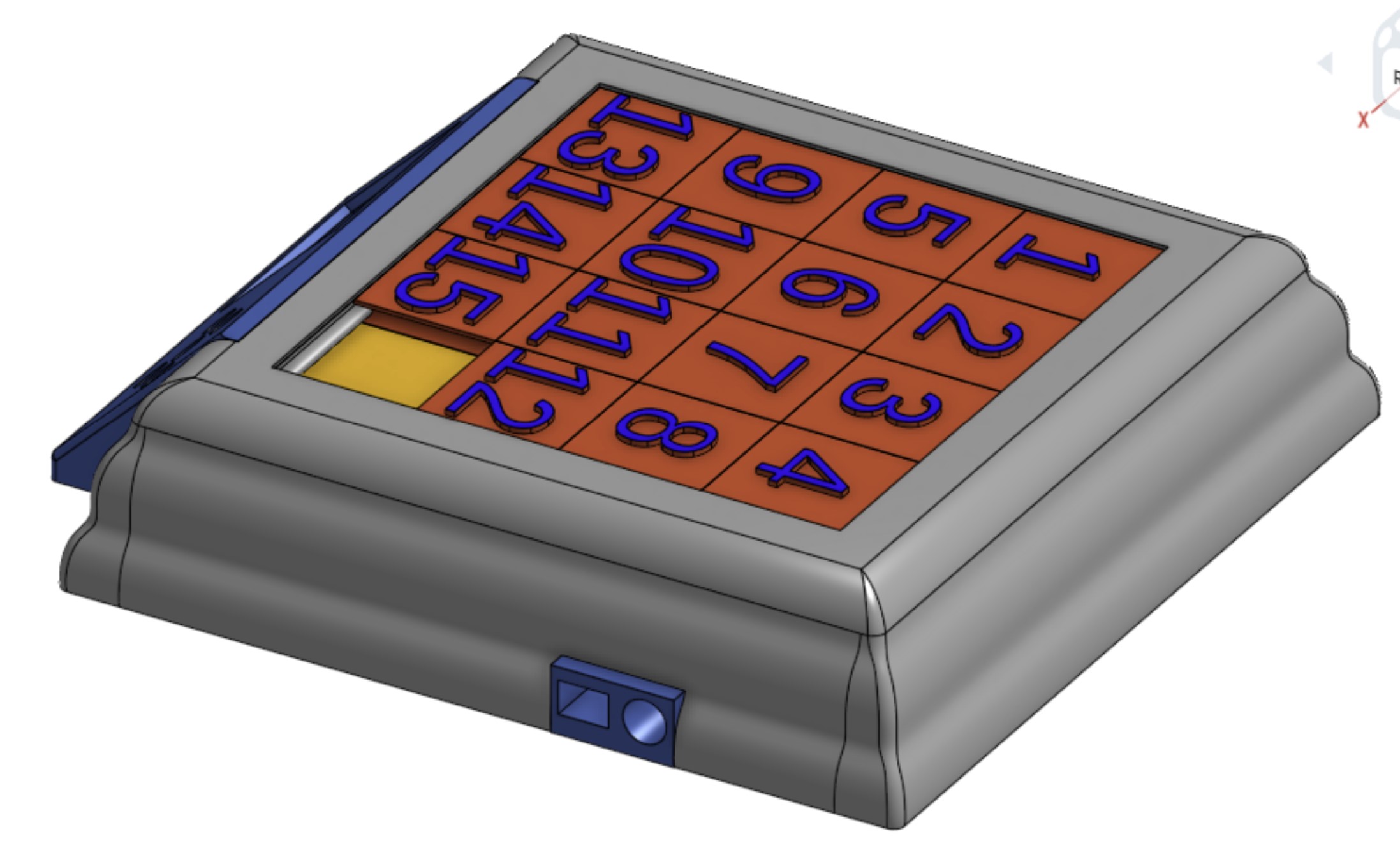
The first big challenge to overcome was the sliding mechanism. I need all the pieces to stay on the board while also offering little friction to sliding. I designed each piece such that they protrude on two sides, and have a track on the other two sides.
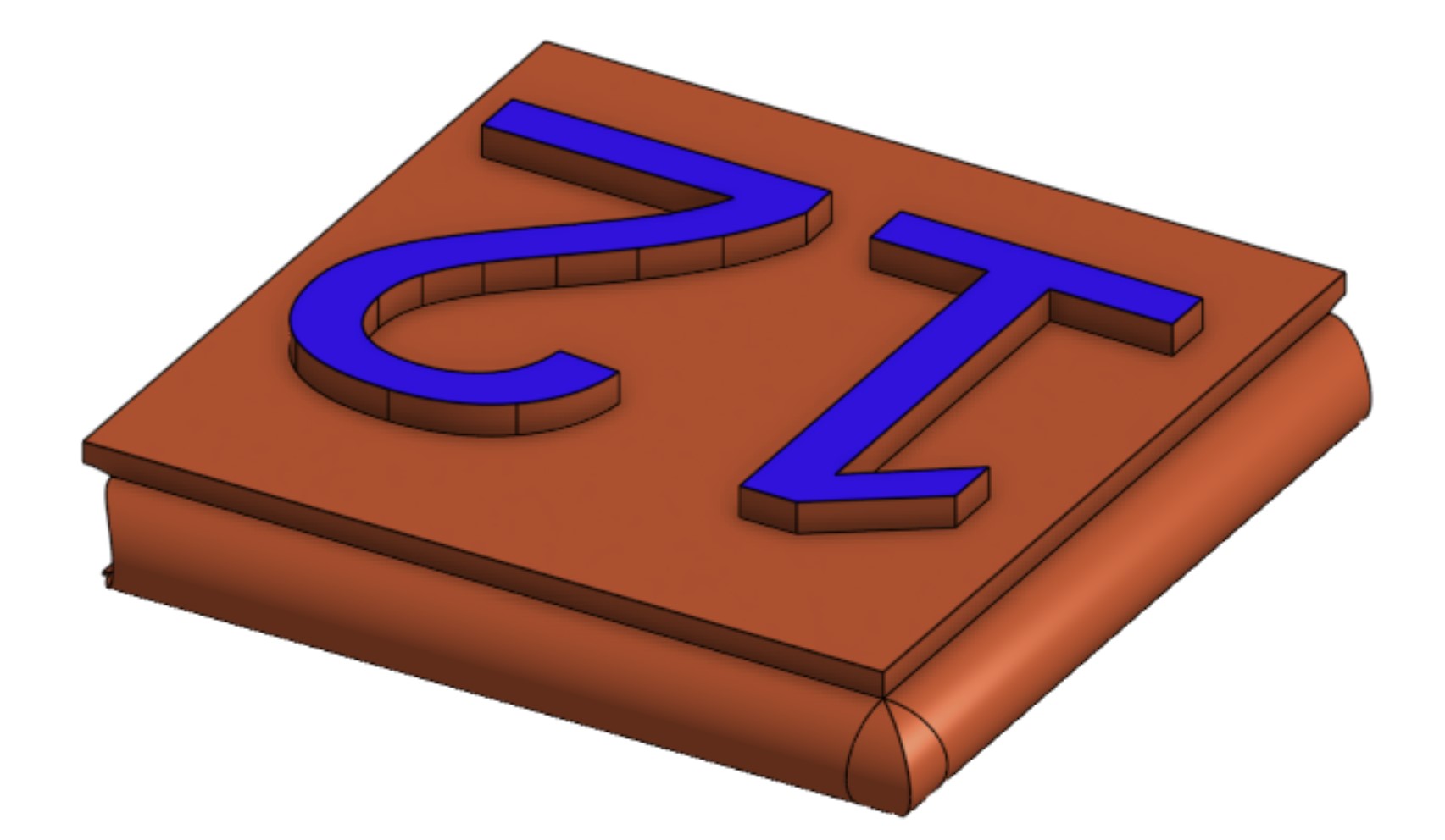
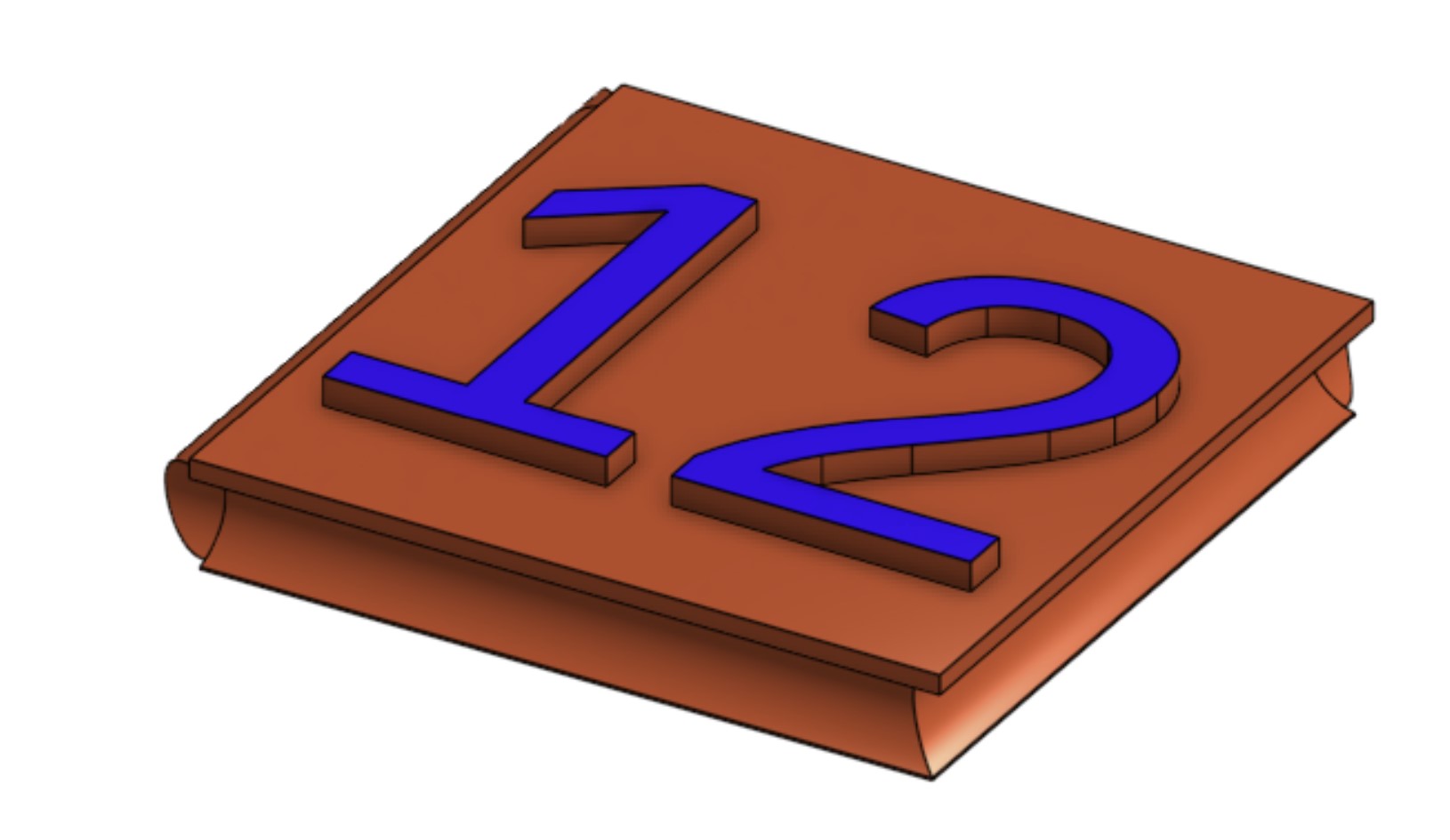
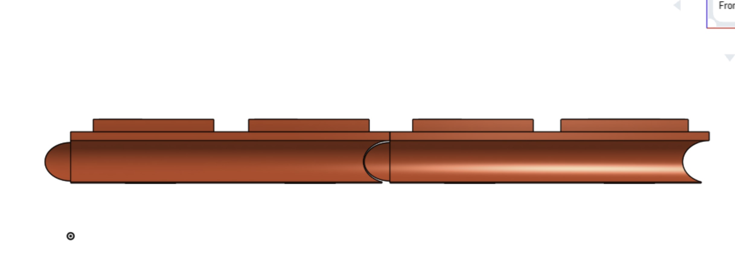 The frame that holds all the pieces together also has these tracks and protrusions. It is held down to a slider bed with M2 screws.
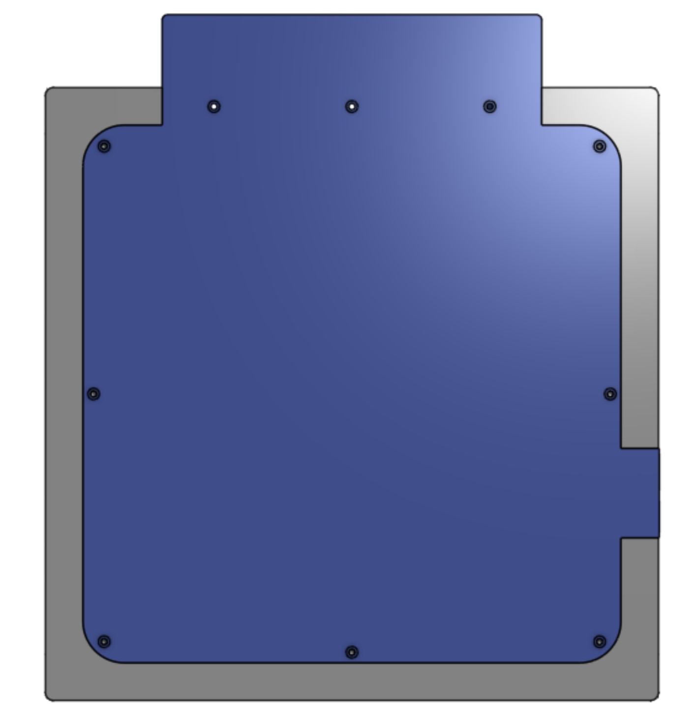
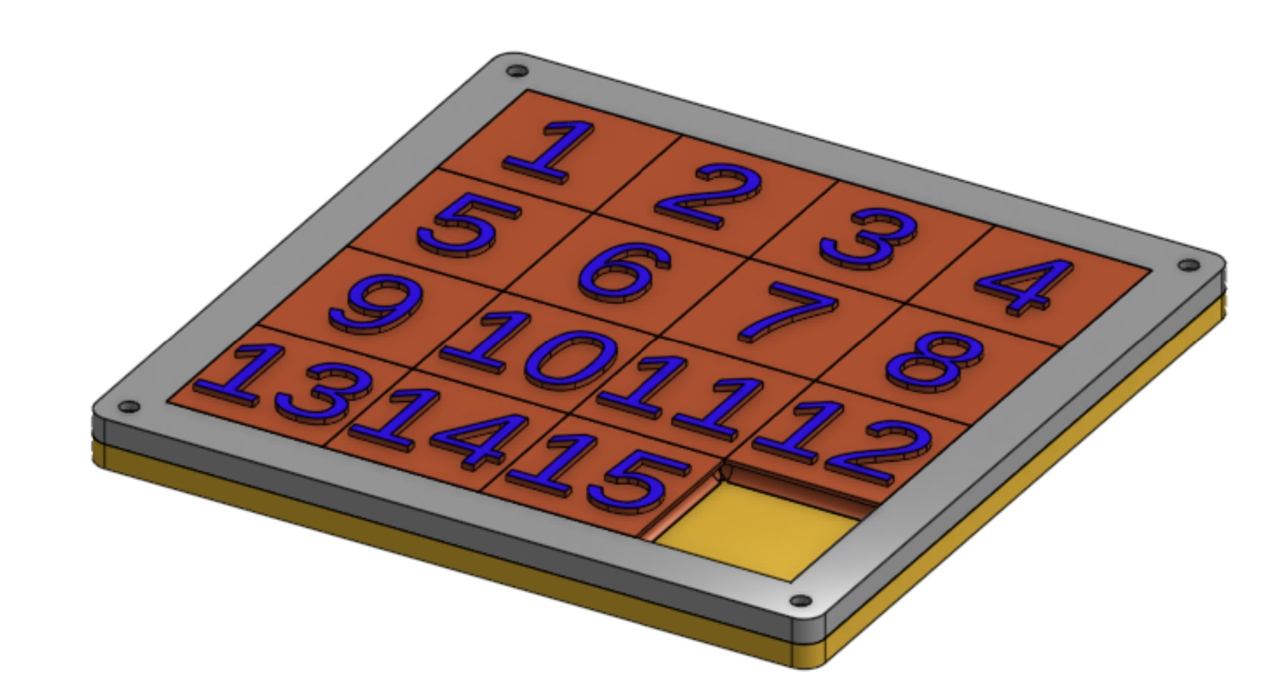 The slider bed also acts to hold the hall effect sensor grid and the retainer for that PCB is the retainer for the main PCB with a smaller retainer on it.
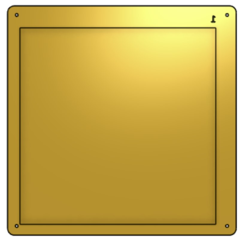
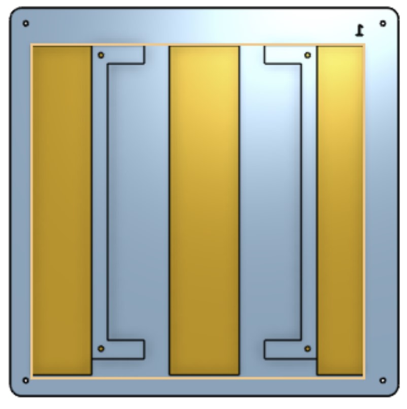
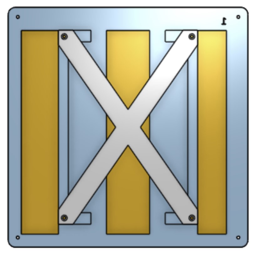
The bottom piece of the unit holds up the slider puzzle, provides a mounting place for a TFT display and 5 input buttons, and a place to plug the machine in and turn it on.
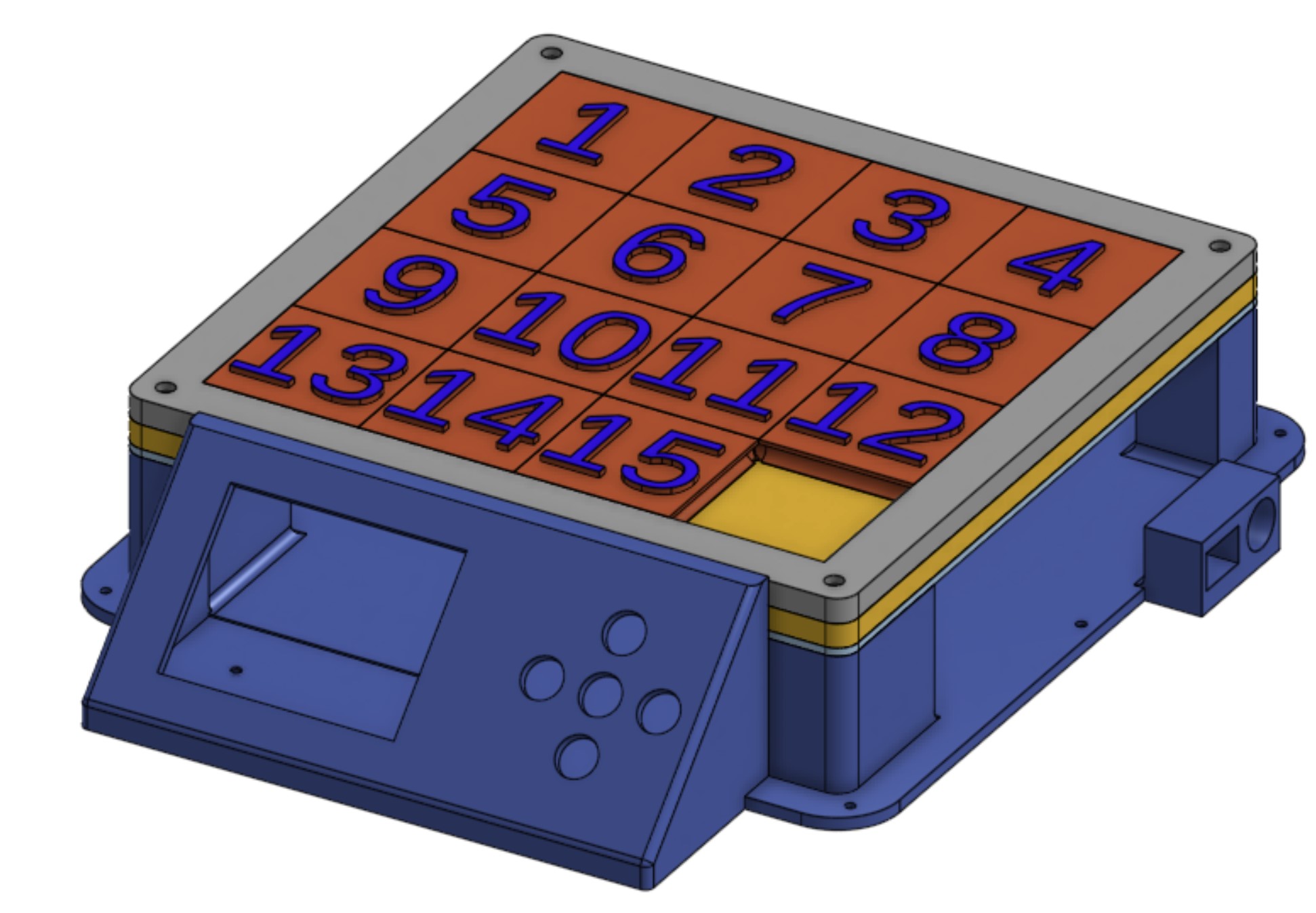
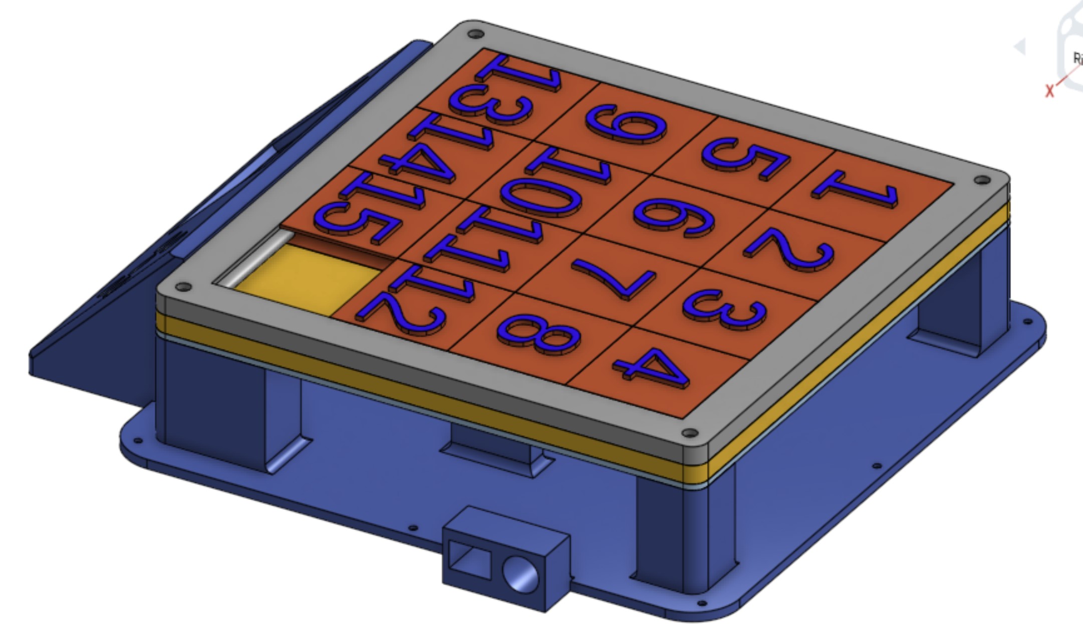

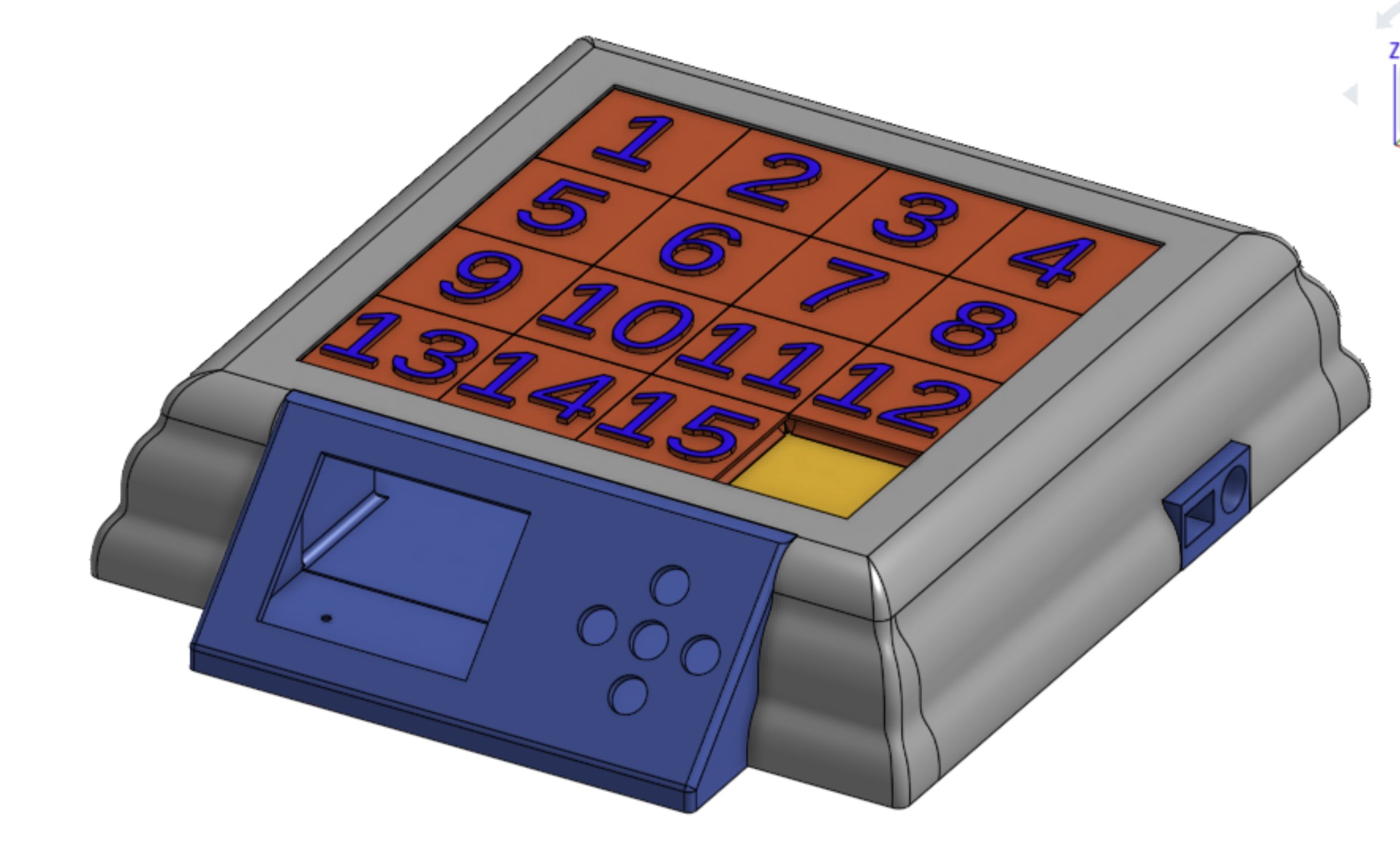
Finally I CADed the main wall to hide all of the electronics and screws. I made it wavy to make it more visually interesting and make it look like it was made on a router.
Electronics Overview
The main challenge with this project is reading the inputs from 64 hall effect sensors. I initially planned to use shift registers to multiplex the 8x8 grid of hall effect sensors to detect the pieces like in the image below.
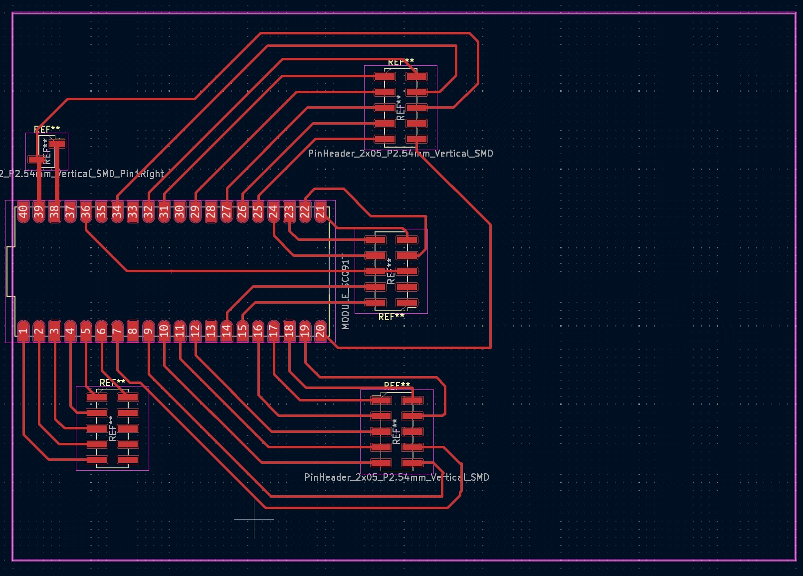
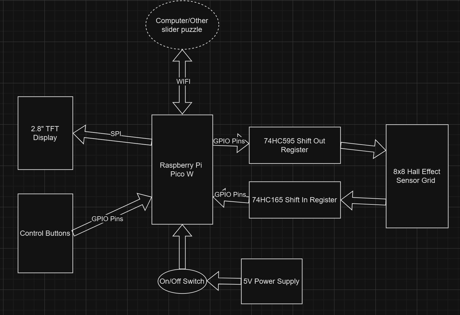 However, I soon realized that using shift registers would be more complicated than helpful because they are 5v devices while the Raspberry Pi Pico is a 3.3v device so I would need a level shifter. After I started designing my PCB, I realized that I had exactly enough GPIO pins to not use the shift registers and do the multiplexing directly from the Pico’s GPIO pins.
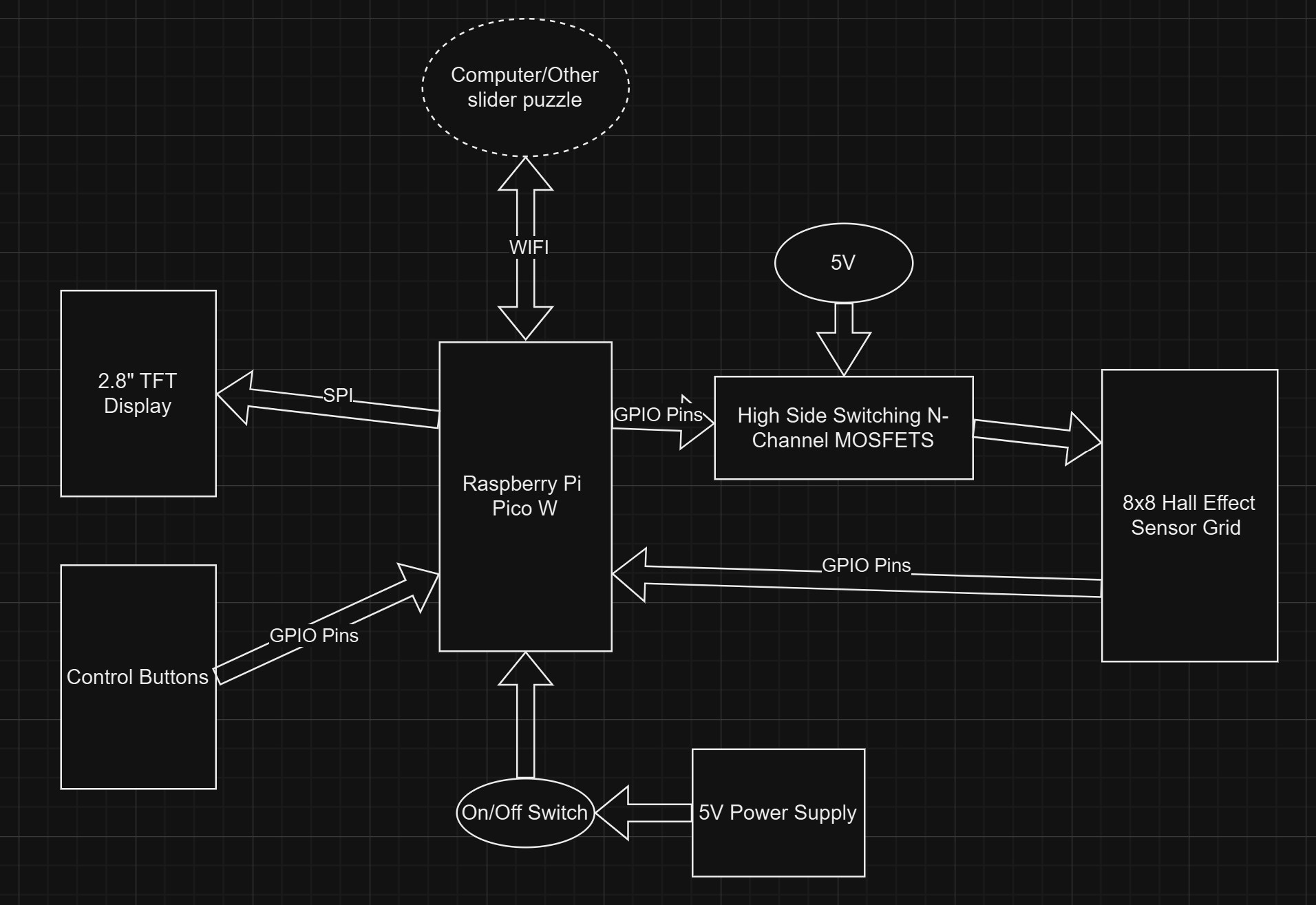 I knew that I could drive the gate of the MOSFETS with a GPIO pin by changing it from input to output. This allowed me to simply break out all the pins from the Pico on my main board which I would then plug other boards into.
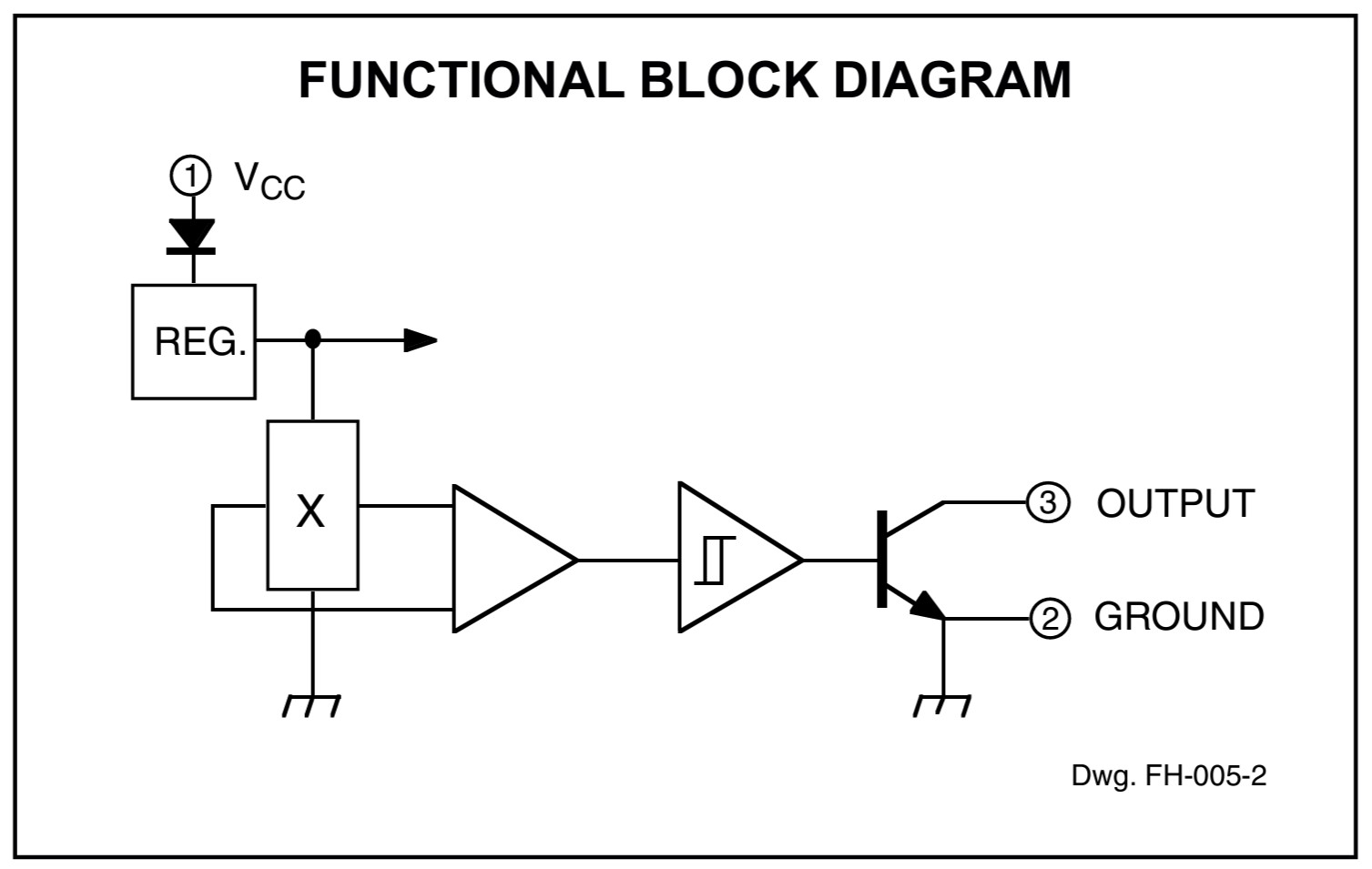
I used the AH3144E digital hall effect sensor to detect the state of the board. As we can see looking at the functional block diagram in the datasheet, this hall effect sensor leaves the output pin floating when it does not detect a magnetic field and ties it to ground when it does detect a magnetic field.
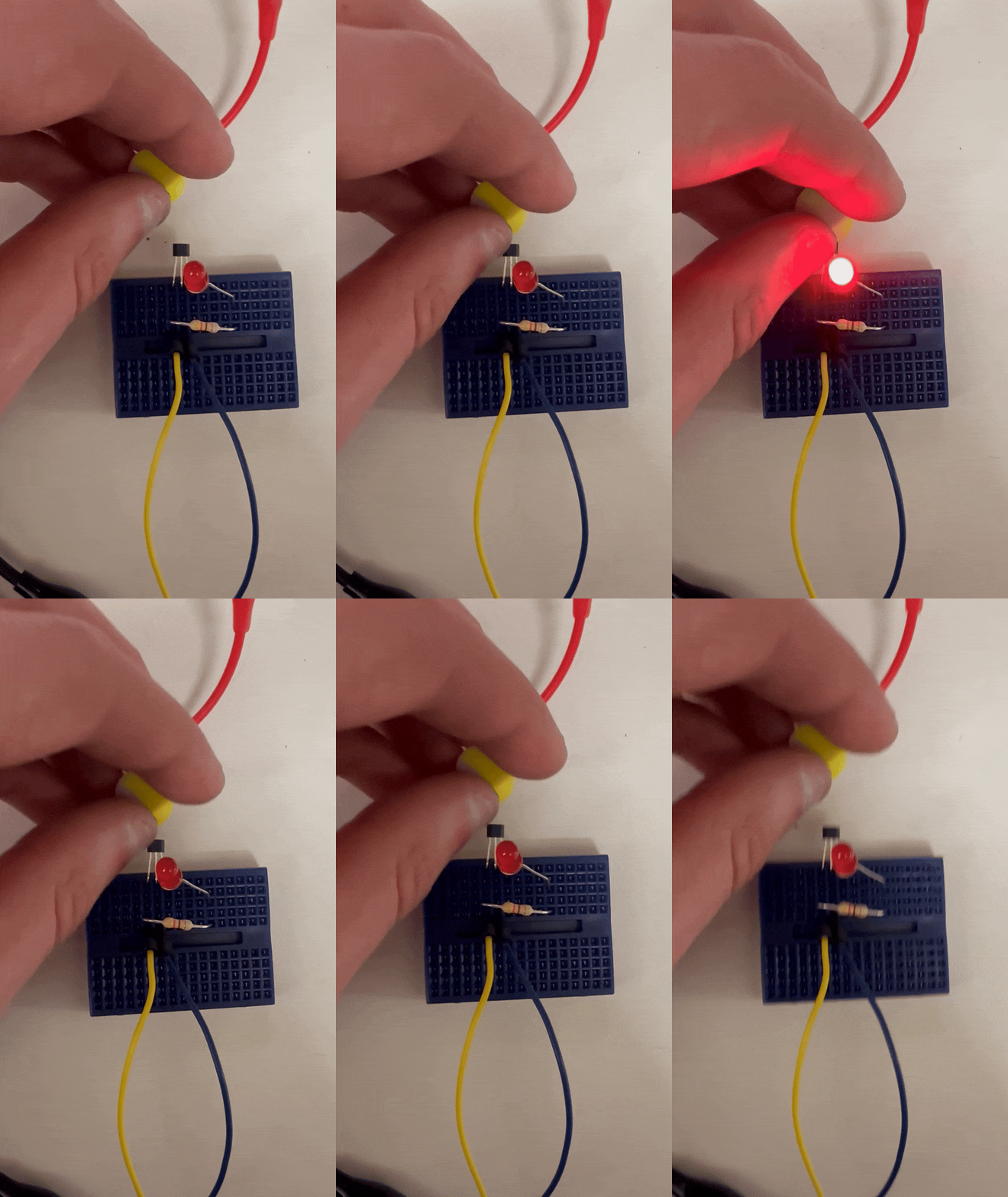
I made the hall effect sensor array with Leo McElroy’s SVG-PCB. You can check out the code I wrote here. I connected all the output lines columns and the power and ground in rows. I planned to connect all the ground pins together and apply 5V through a MOSFET to the row I am interested in reading. I then read the output from the columns with a GPIO pin with the internal pullup resistor enabled.
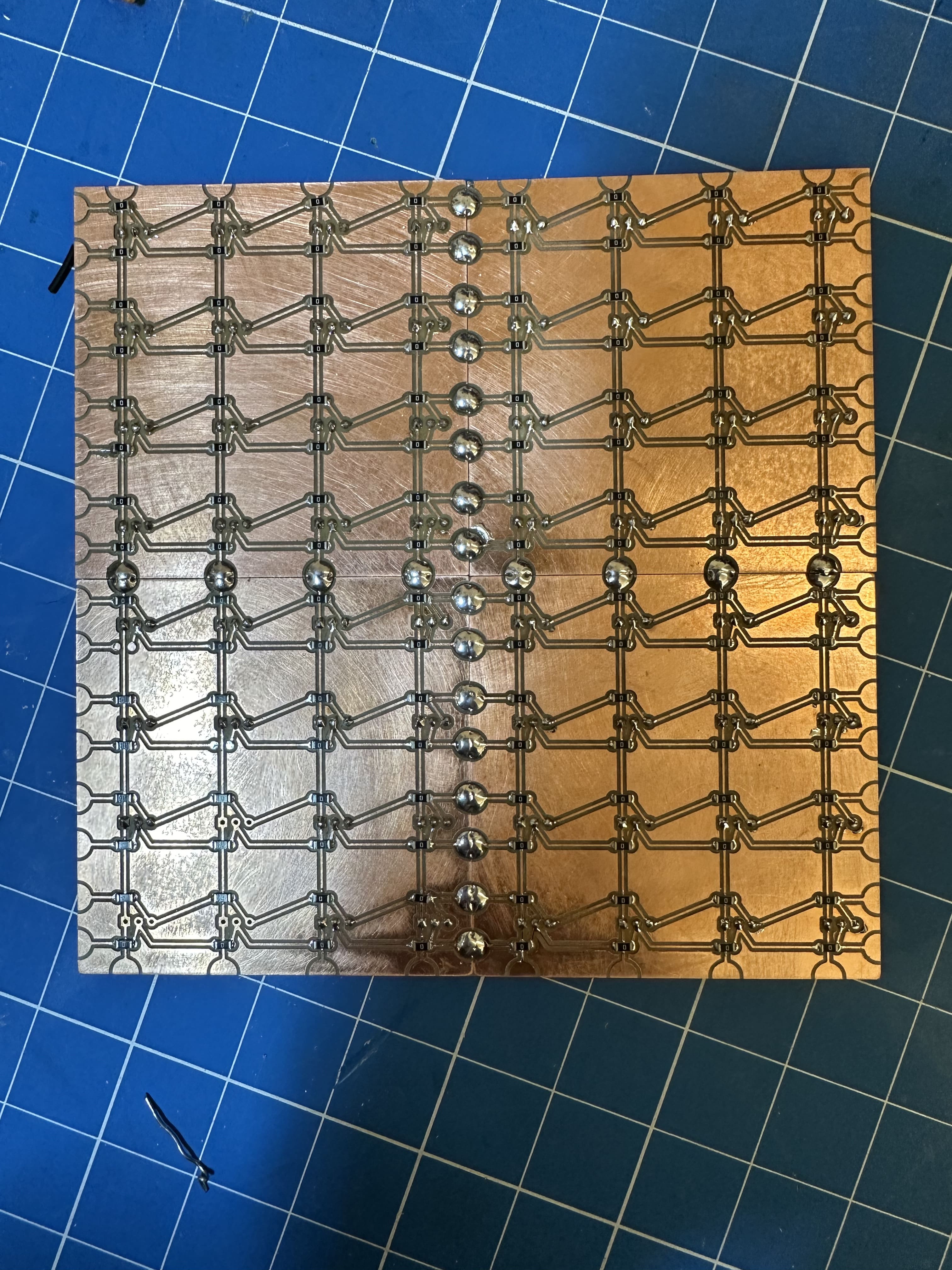
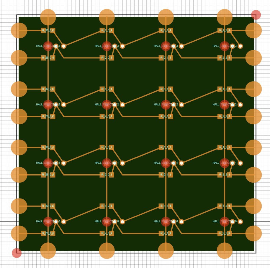 The PCB is modular and allows you to tile it to make an arbitrarily large grid. I only need 4 of these for my project.
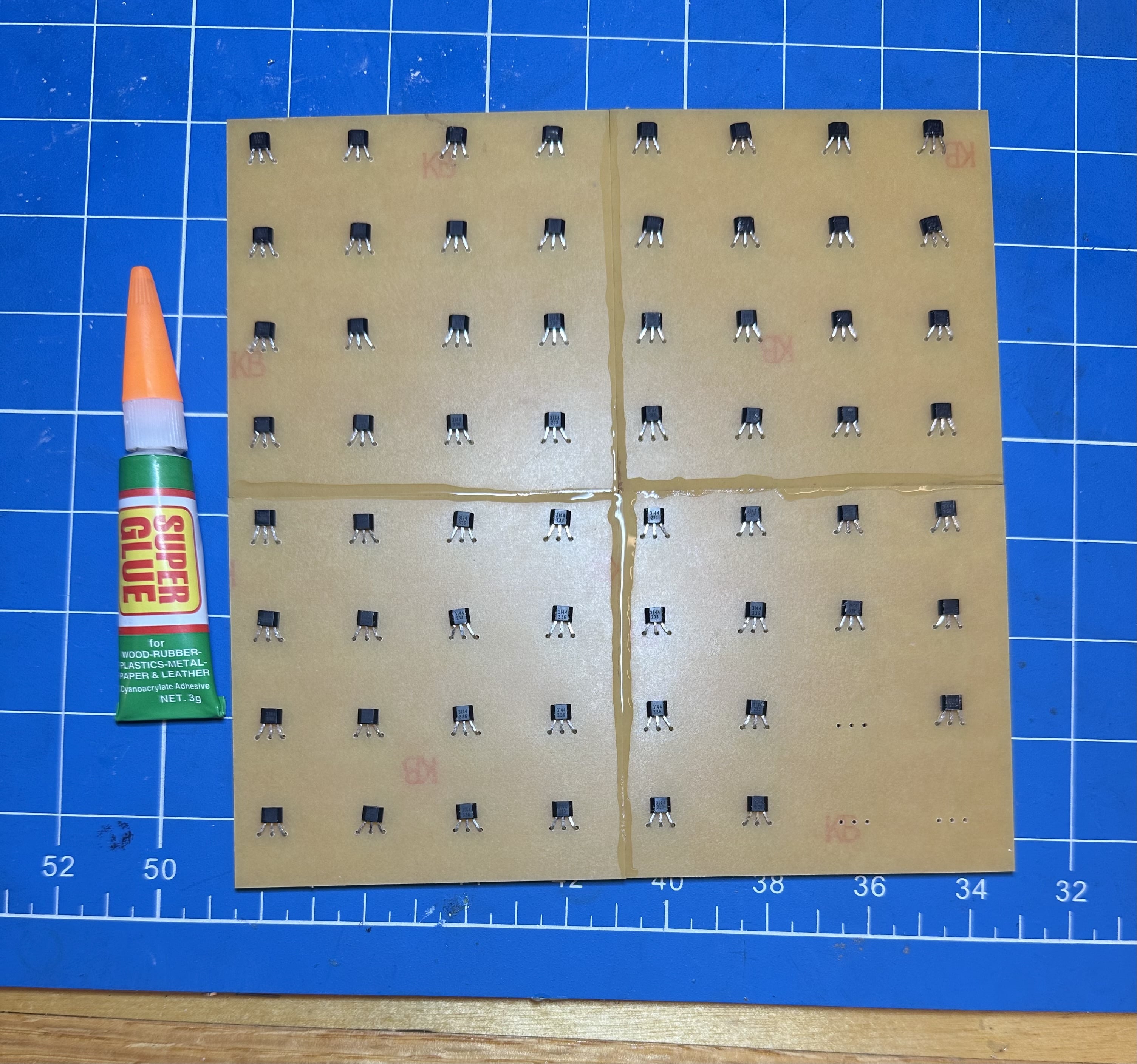
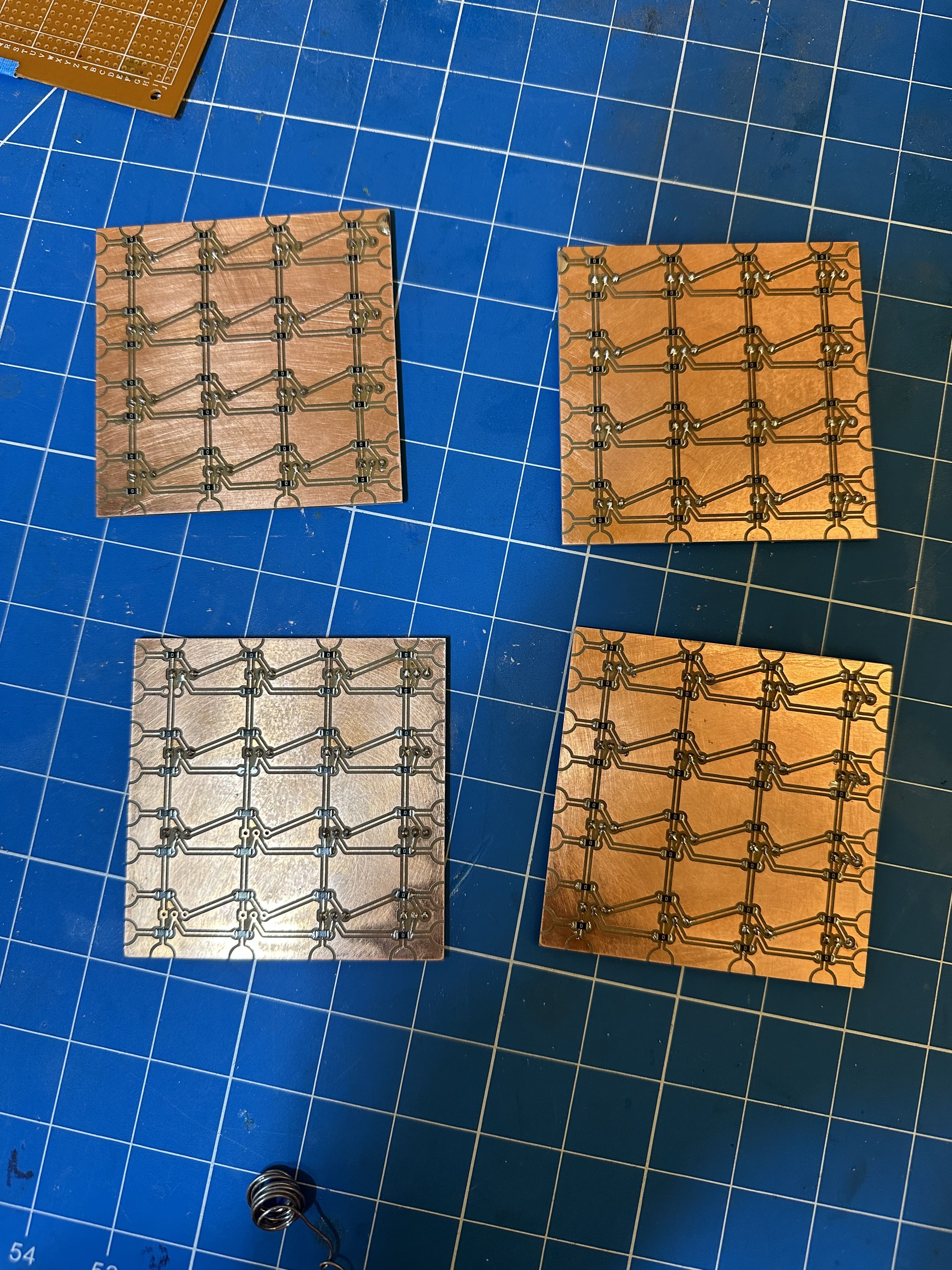 I then populated the boards and soldered and glued them together.
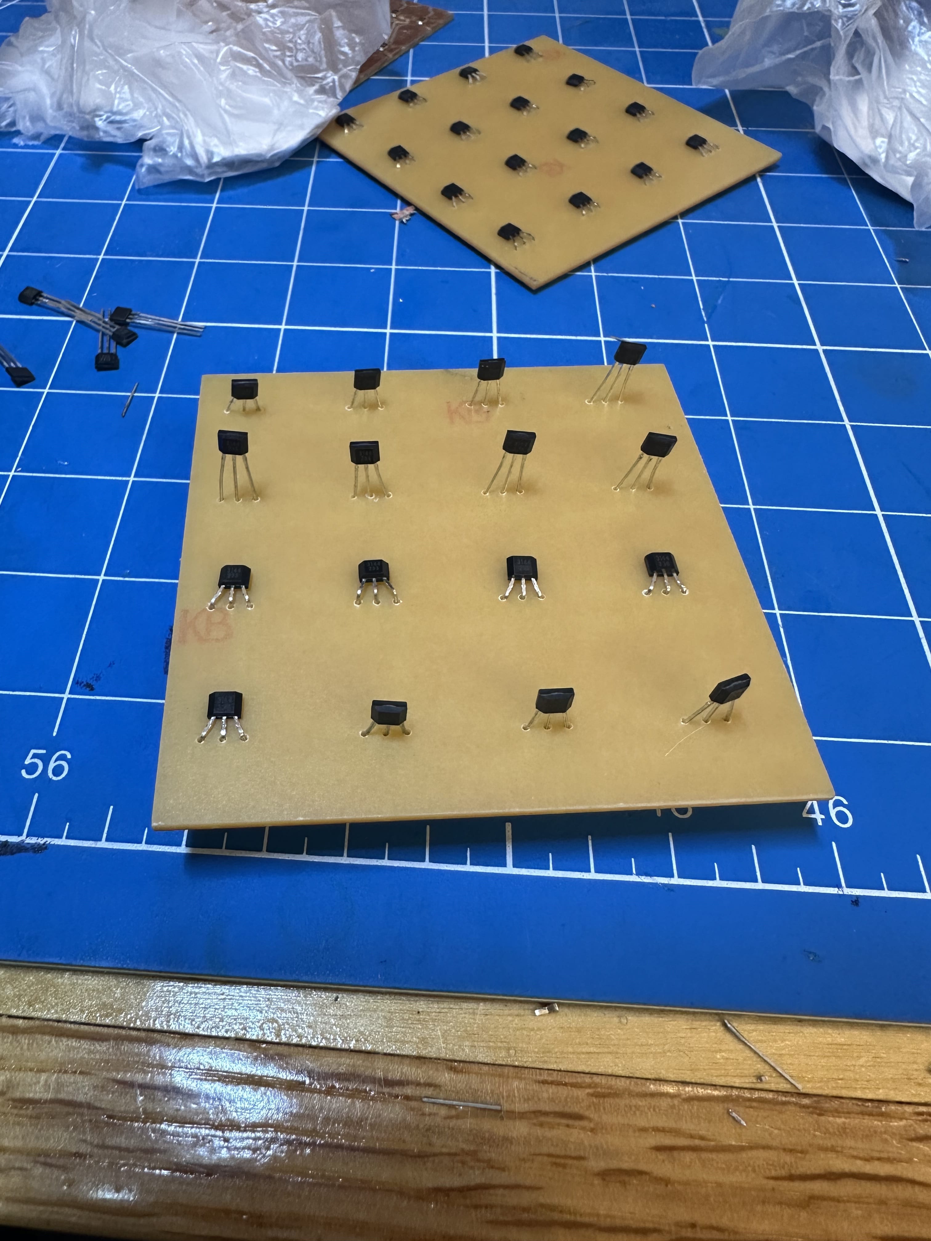
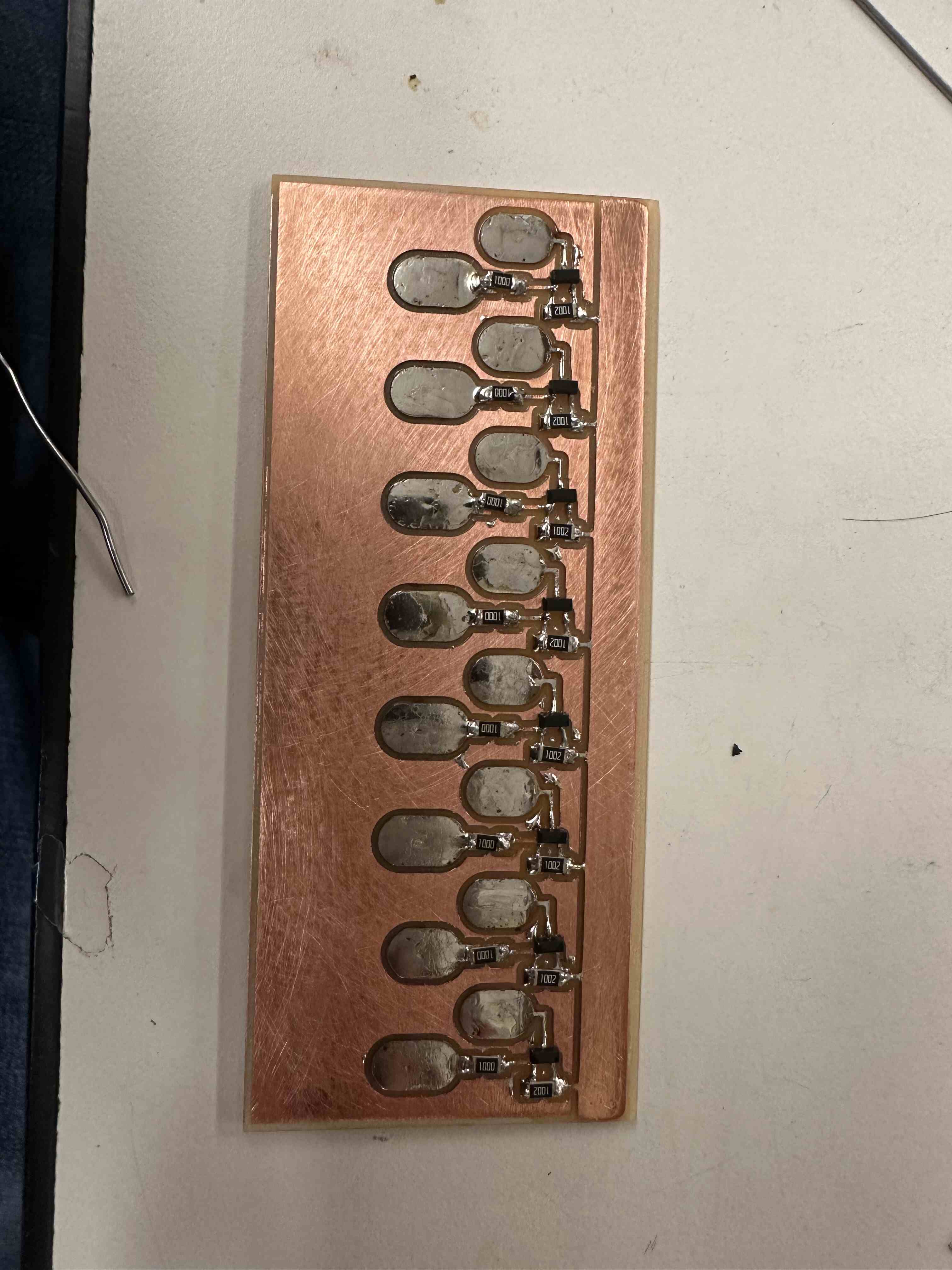
The high side switching board was again designed in SVG-PCB.
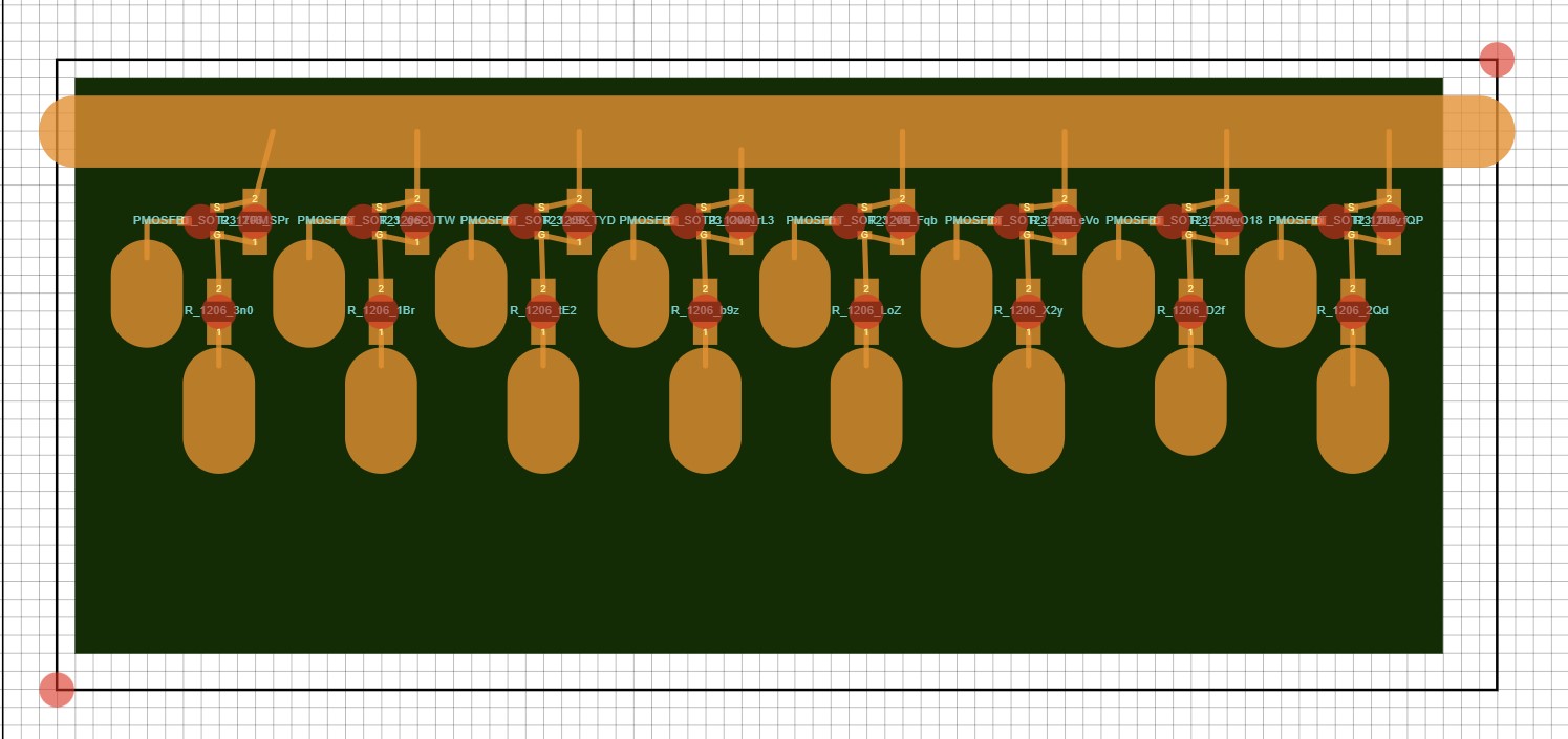 And hand soldered together.
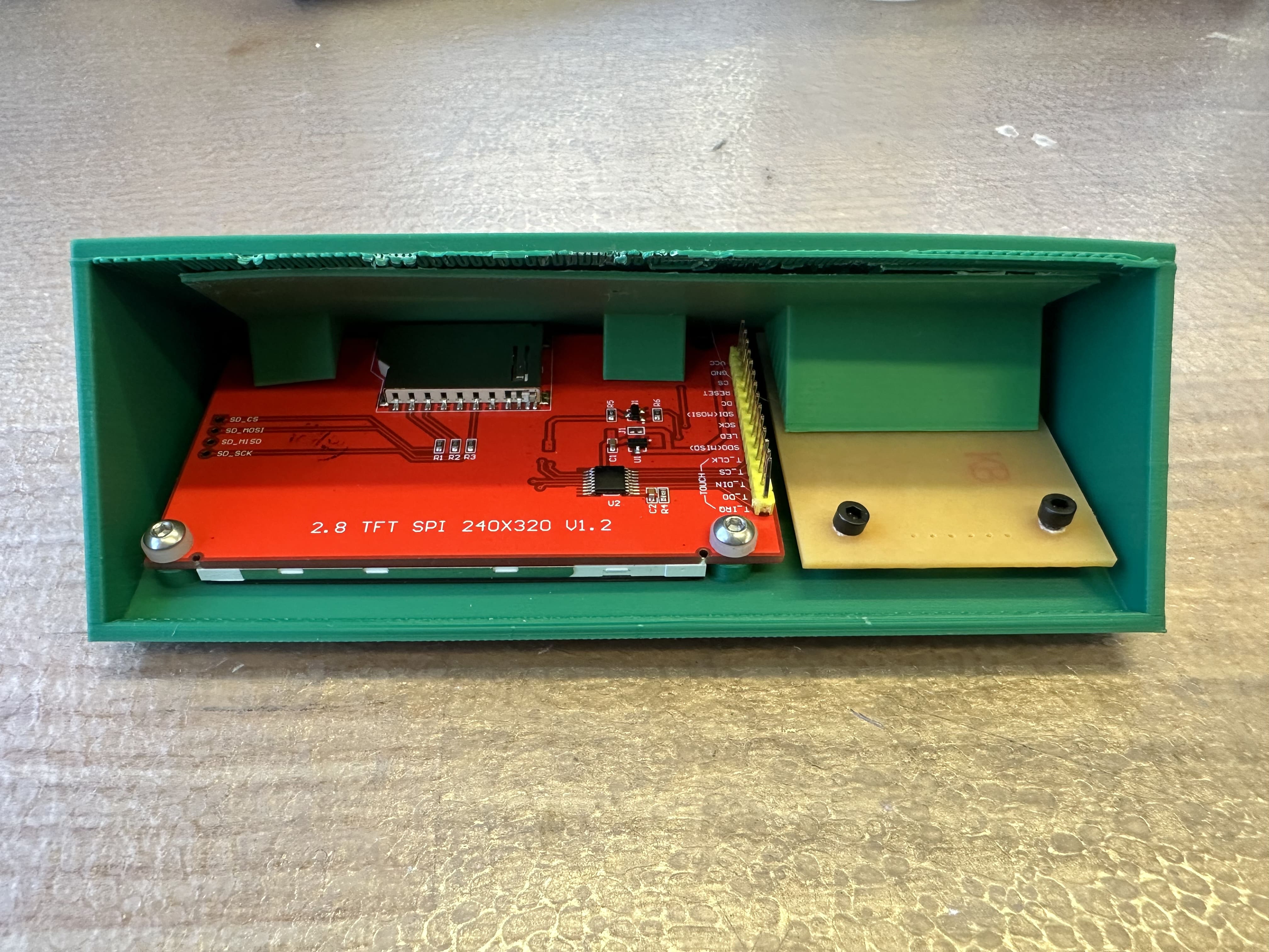
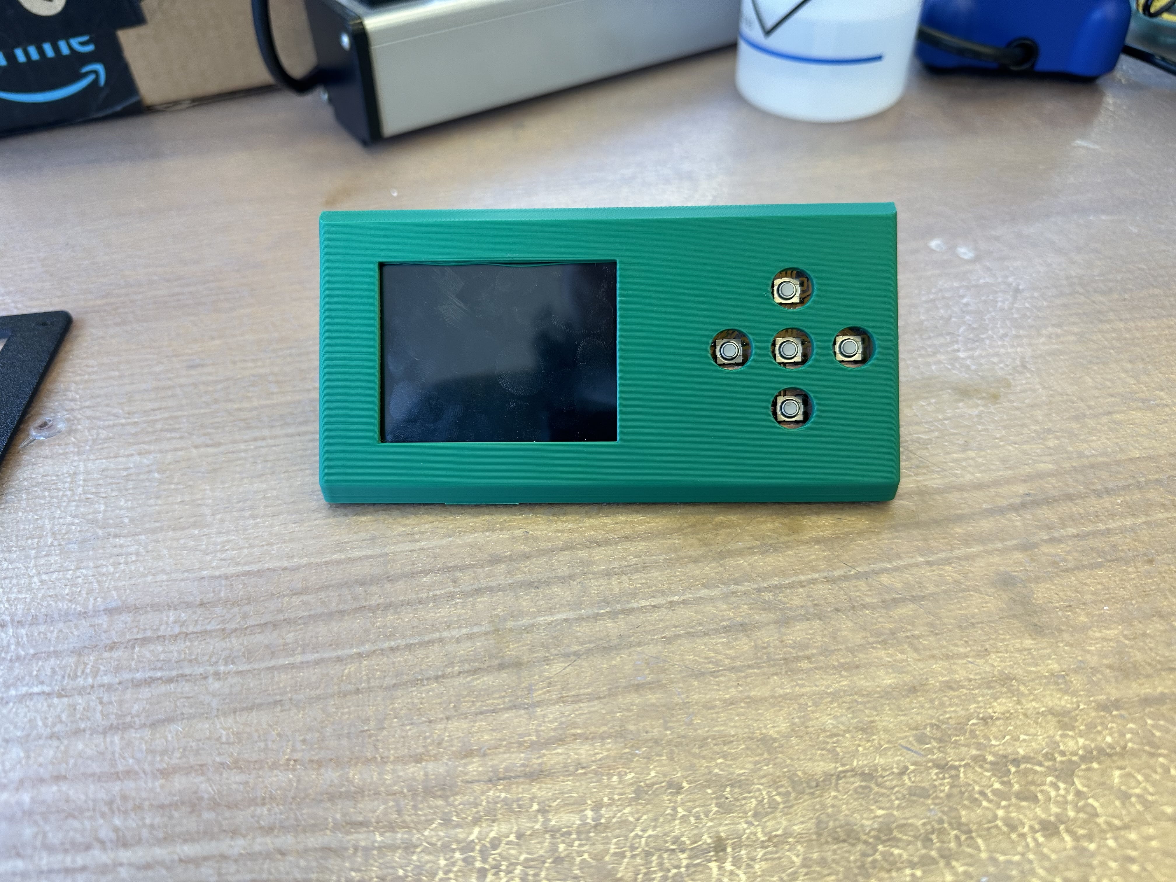
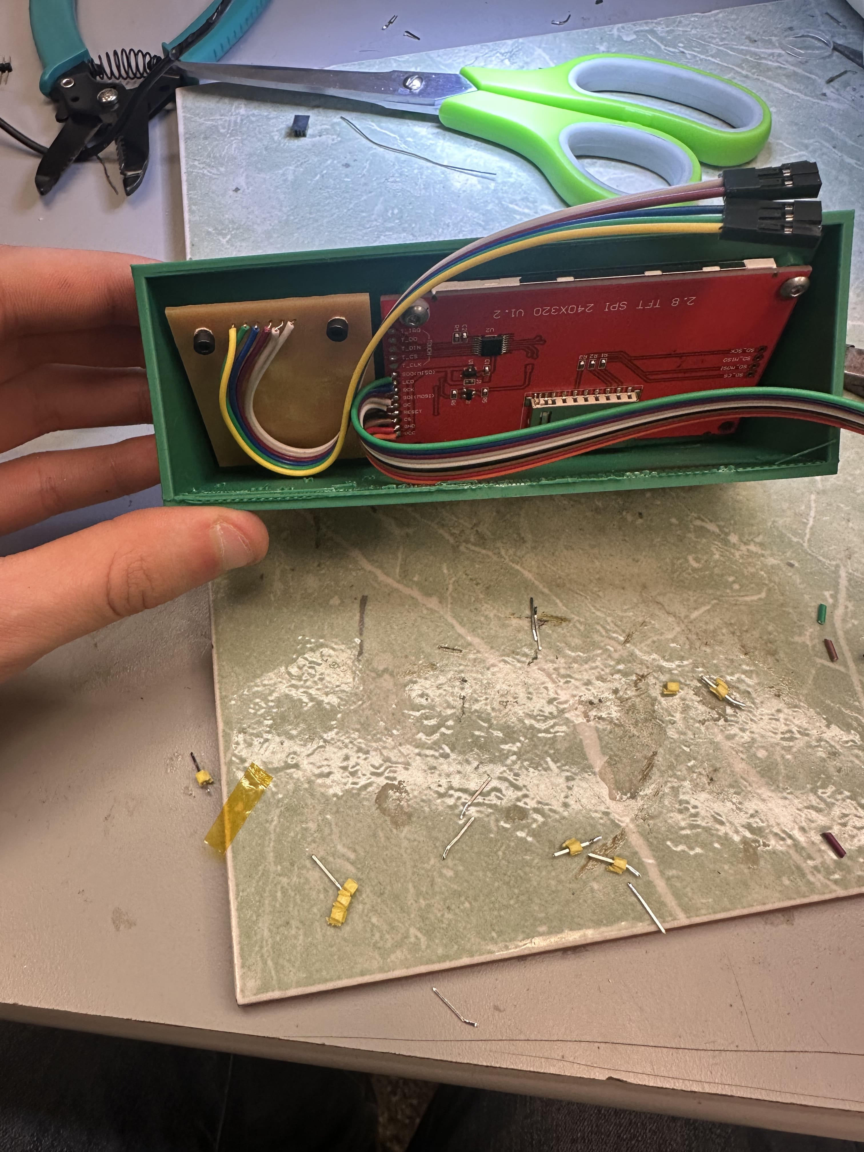
I used a 2.8" TFT 240x320 pixel display that communicated over SPI to give user feedback. The user can navigate this screen using 5 buttons to the right of it on a small button panel.
Manufacturing
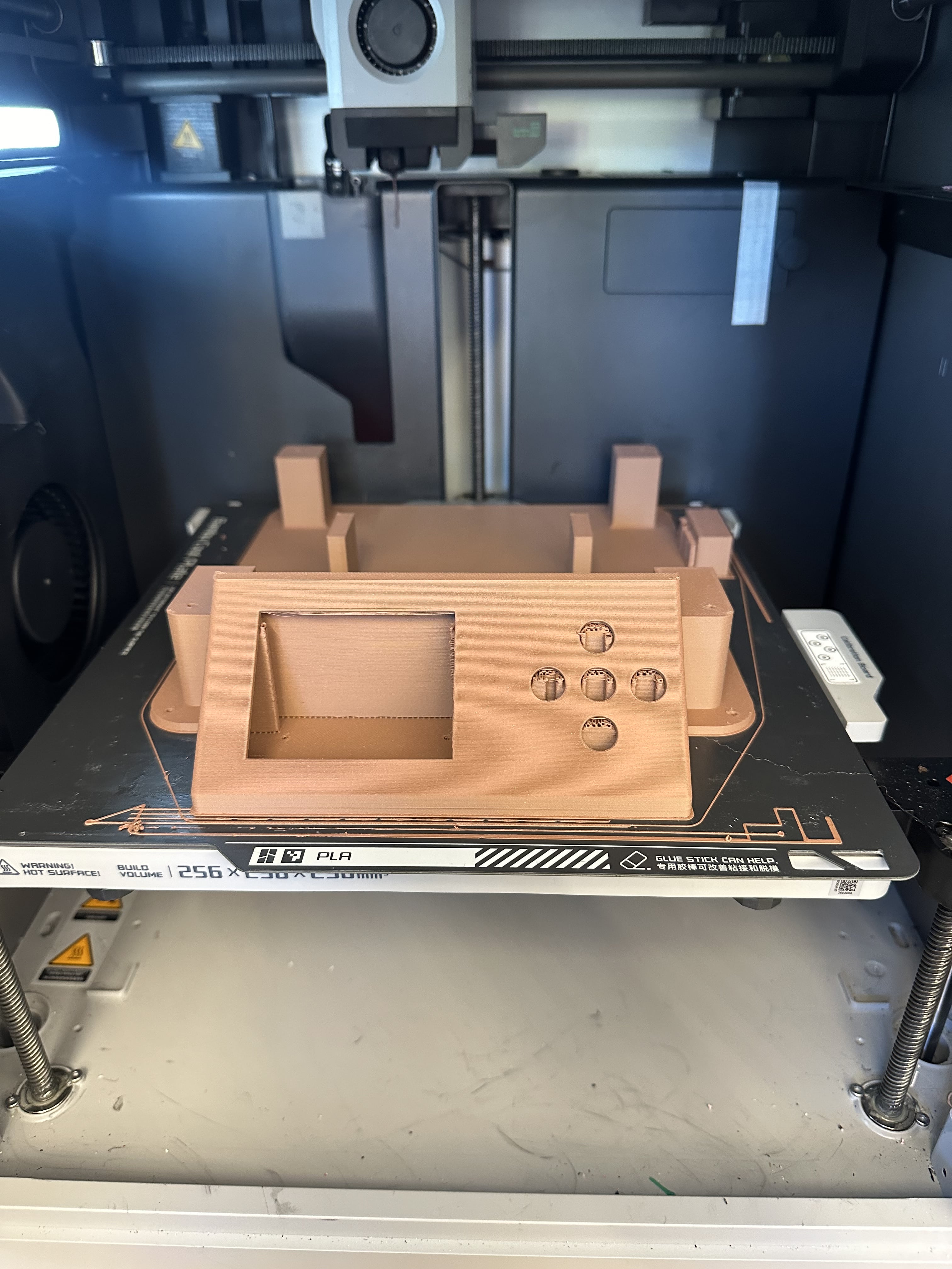
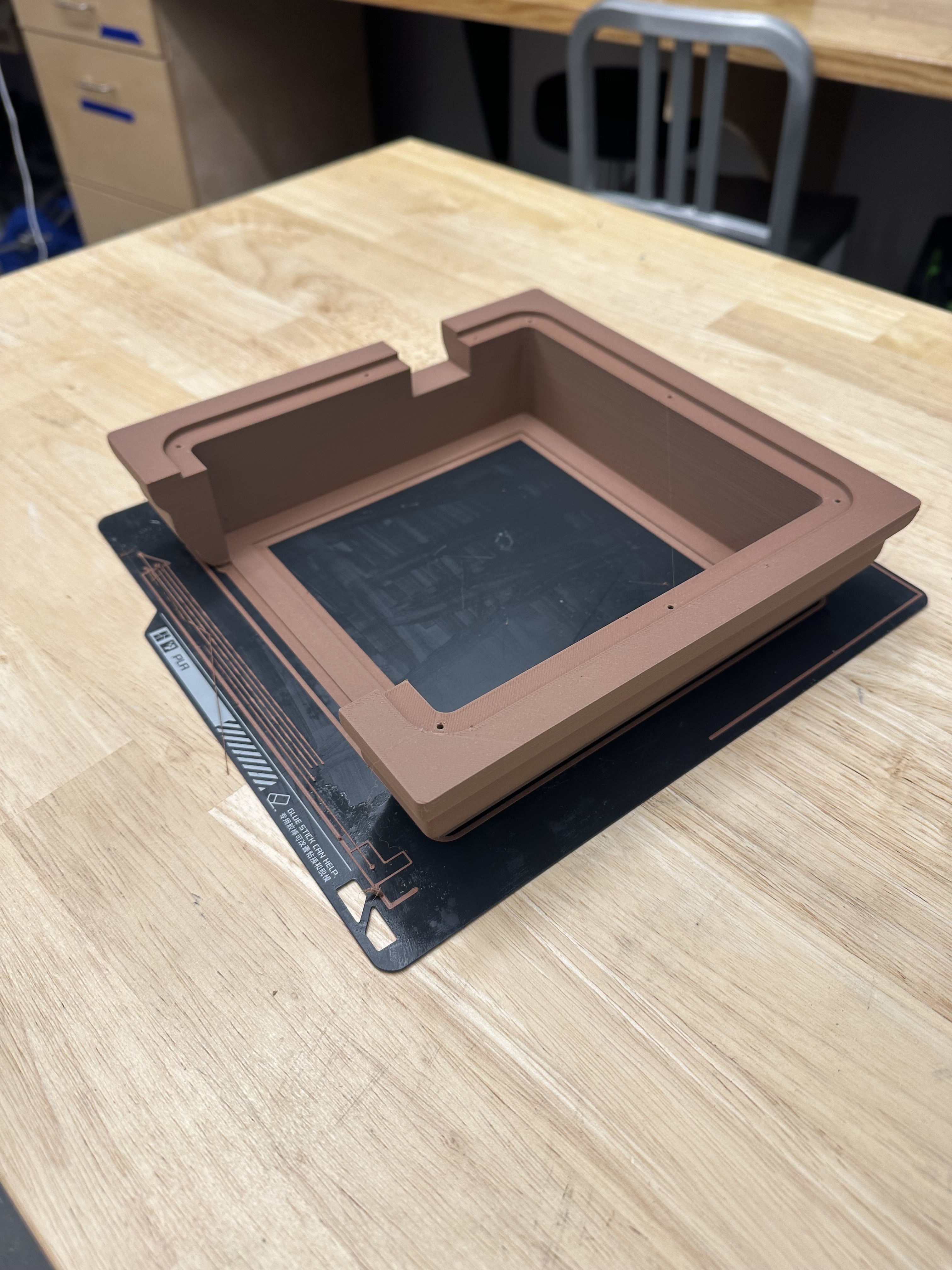
The manufacturing for this design was relatively straightforward because I designed everything to be 3D printable and fit together with screws.
 Now comes the hard part: the electronics manufacturing.
I was happy that the hall effect sensor board perfectly slotted into the back of the slider puzzle.
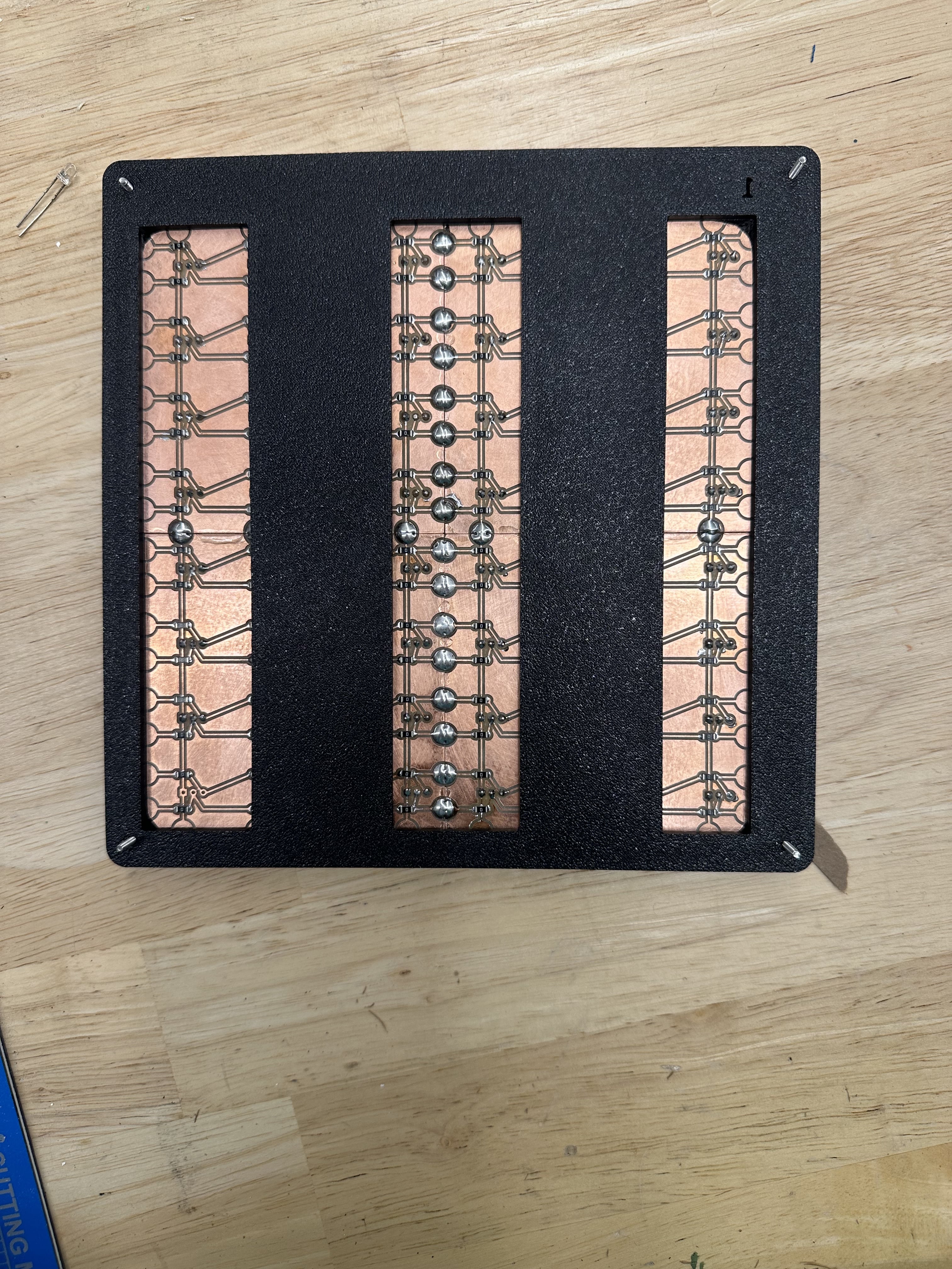
I then milled and soldered together the main board with my Pico. I am a big fan of the ribbon cable that I used. It made the inside of my project more colorful than a pride parade and helped a ton with wire management and easy debugging as I could plug and unplug boards as I was testing them!
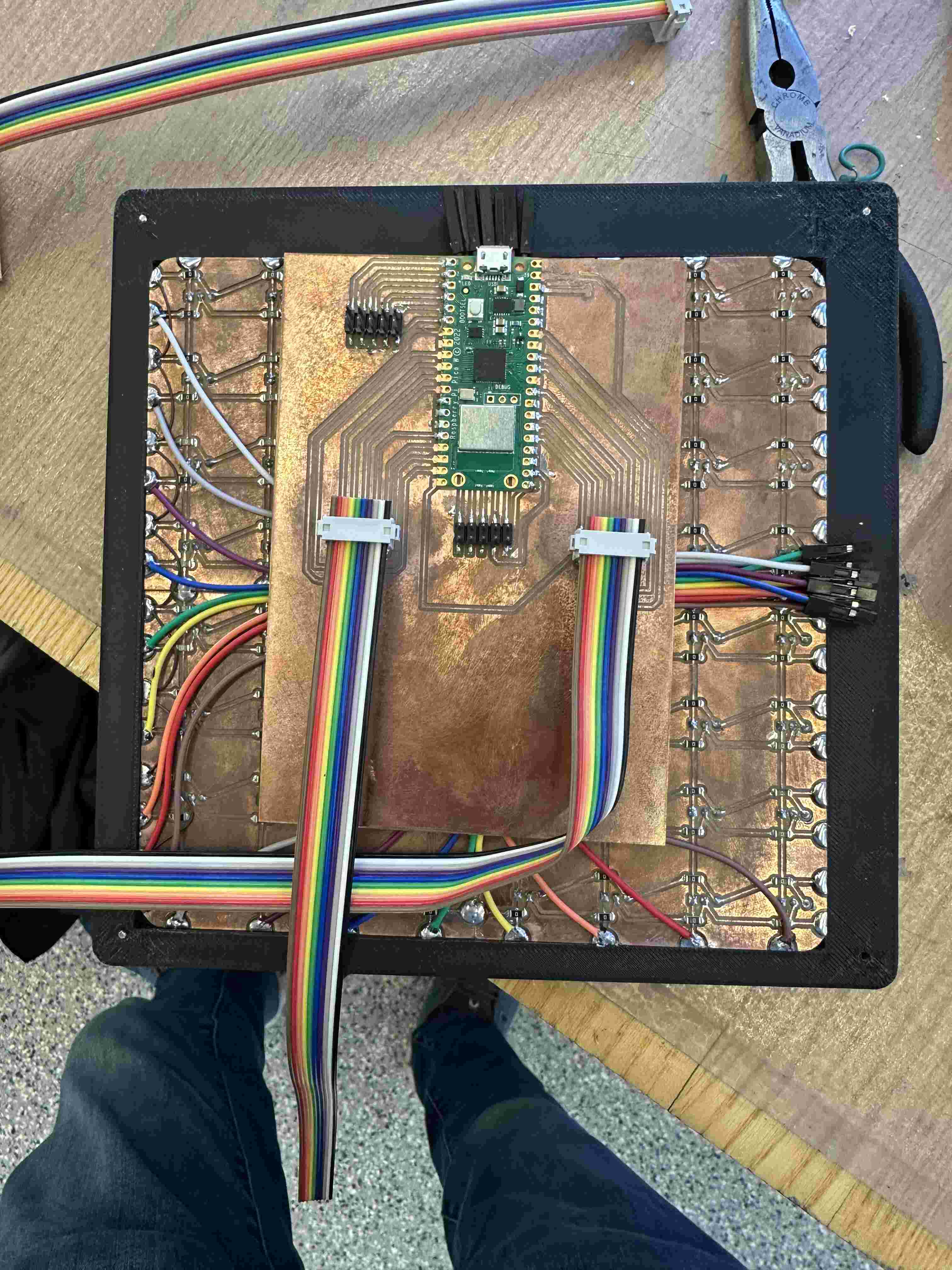
I soldered everything in place and secured my boards with some 3D printed brackets.
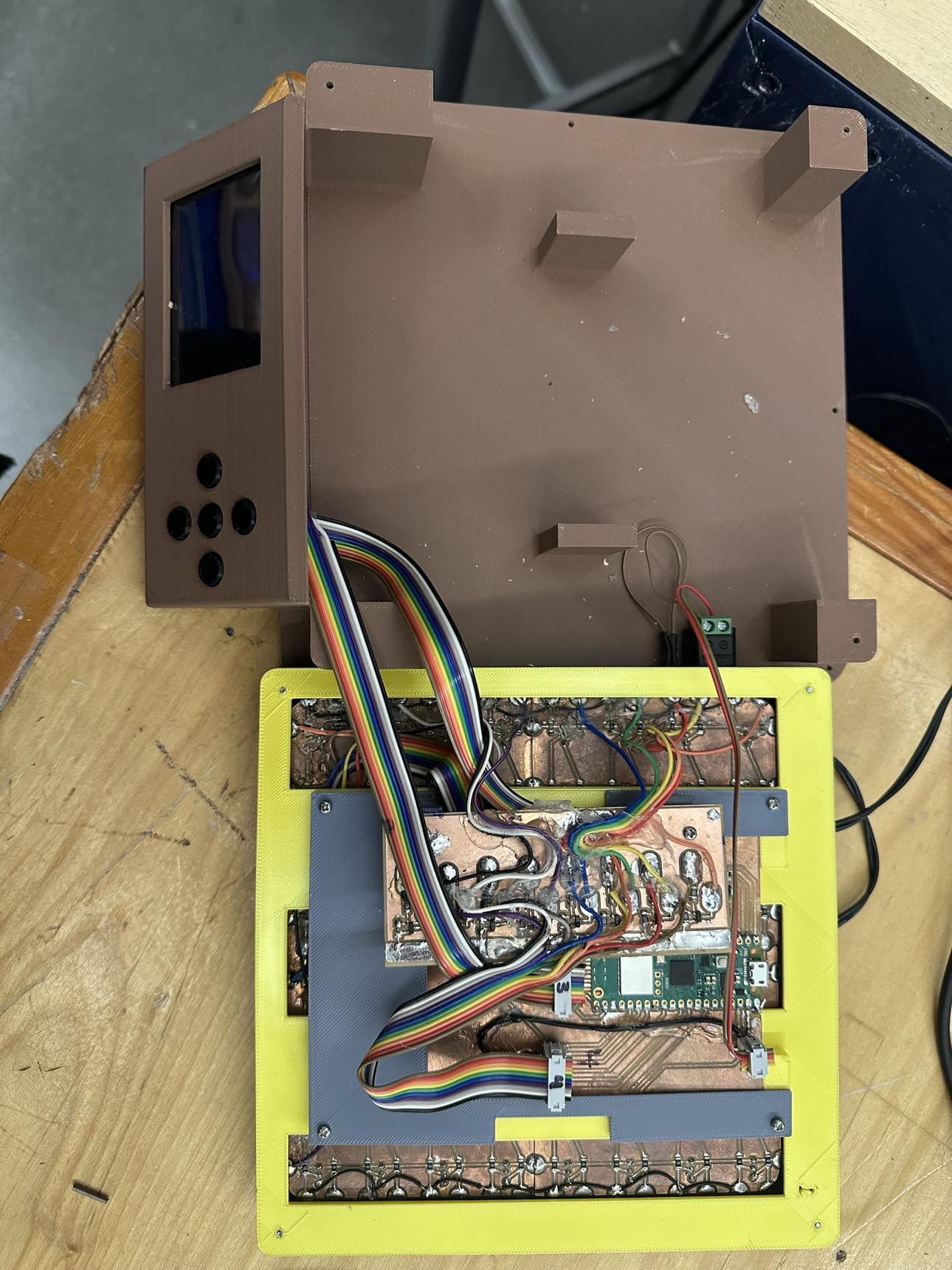
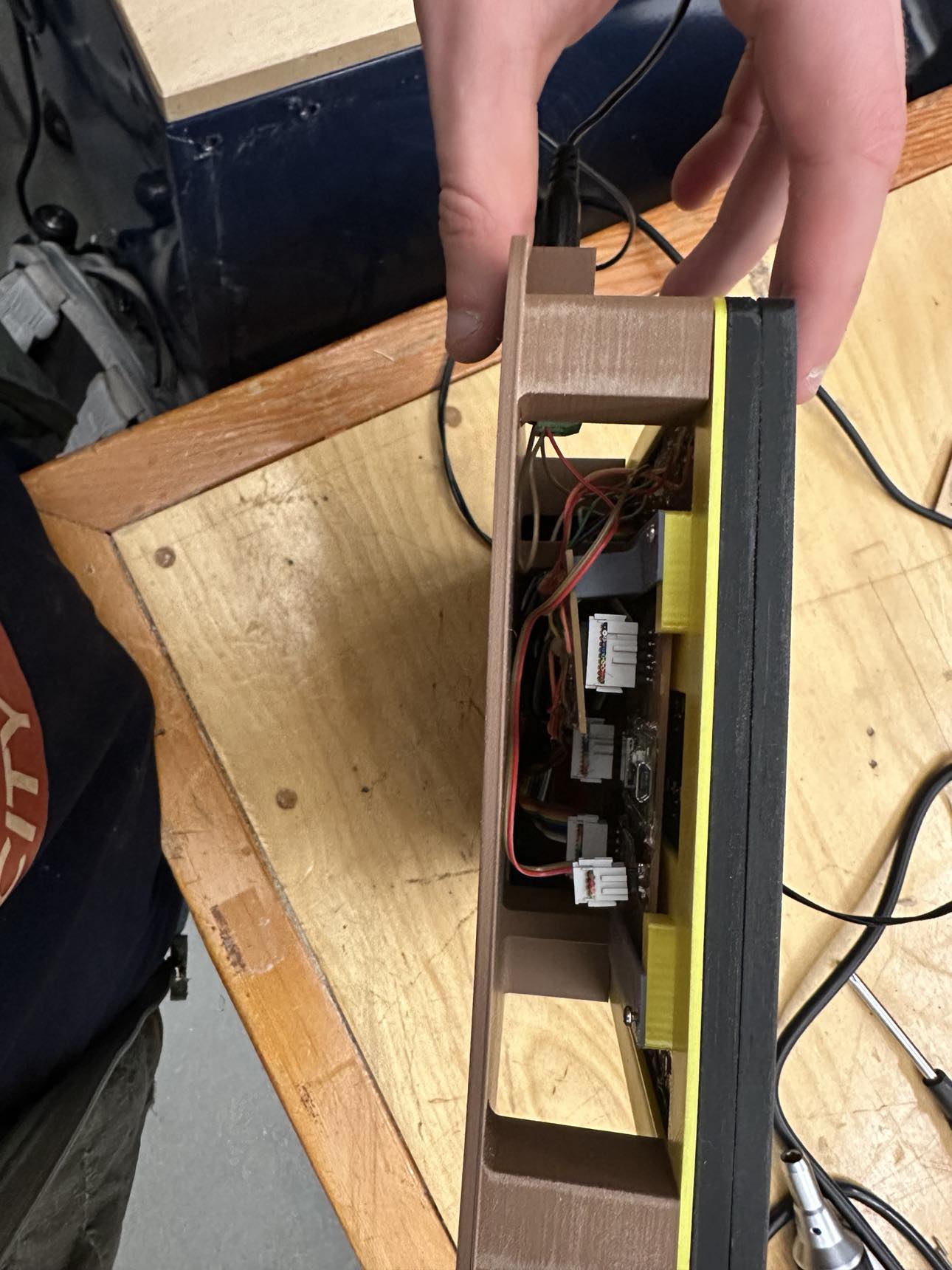
Coding
I began by trying to interface with the TFT display I was using. I decided to use circuit python in Thonny because then I could use Adafruit’s ili9341 library.
I then tested out multiplexing the hall effect sensors. The code was relatively straightforward. I found that I could drive the gate of the p-channel mosfets by switching the pins connected to it from an input to an output.
import board
import digitalio
import time


# Define the input pins
input_pins = [
    digitalio.DigitalInOut(board.GP5),
    digitalio.DigitalInOut(board.GP6),
    digitalio.DigitalInOut(board.GP7),
    digitalio.DigitalInOut(board.GP8),
    digitalio.DigitalInOut(board.GP9),
    digitalio.DigitalInOut(board.GP12),
    digitalio.DigitalInOut(board.GP13),
    digitalio.DigitalInOut(board.GP14)
]
input_pins.reverse()


# Define the output pins
output_pins = [
    digitalio.DigitalInOut(board.GP15),
    digitalio.DigitalInOut(board.GP19),
    digitalio.DigitalInOut(board.GP20),
    digitalio.DigitalInOut(board.GP21),
    digitalio.DigitalInOut(board.GP22),
    digitalio.DigitalInOut(board.GP26),
    digitalio.DigitalInOut(board.GP27),
    digitalio.DigitalInOut(board.GP28)
]


# Configure input pins as inputs with pull-down resistors
for pin in input_pins:
    pin.direction = digitalio.Direction.INPUT
    pin.pull = digitalio.Pull.UP


# Configure output pins as outputs
for pin in output_pins:
    pin.direction = digitalio.Direction.INPUT
    #pin.value = 1  # Set high initially to turn off P-channel MOSFETs


def read_and_write_gpio():
    while True:
        states = []
        for pin in output_pins:
            pin.direction = digitalio.Direction.OUTPUT
            time.sleep(0.001)
            states.append([1 if p.value else 0  for p in input_pins])
            pin.direction = digitalio.Direction.INPUT
        for row in states:
            print(row)
        print("\n")
        time.sleep(1)


# Call the main function to handle GPIO
read_and_write_gpio()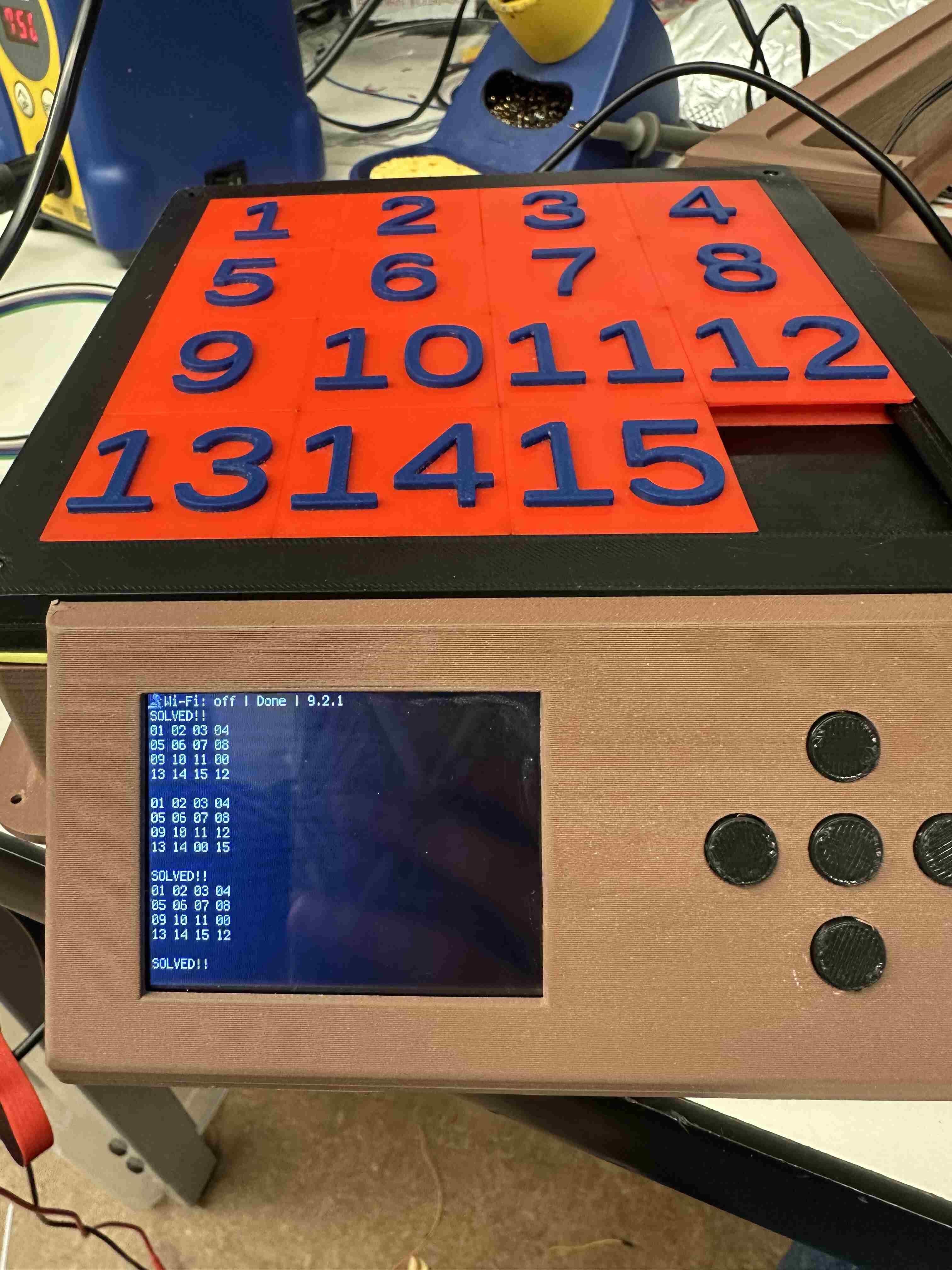
I could then easily connect the two functionalities together.
The REAL Motivation
You would think that the motivation to solve the puzzle quickly would come from minimizing your time. However, I found something that motivates me even more to get things done in a short amount of time:
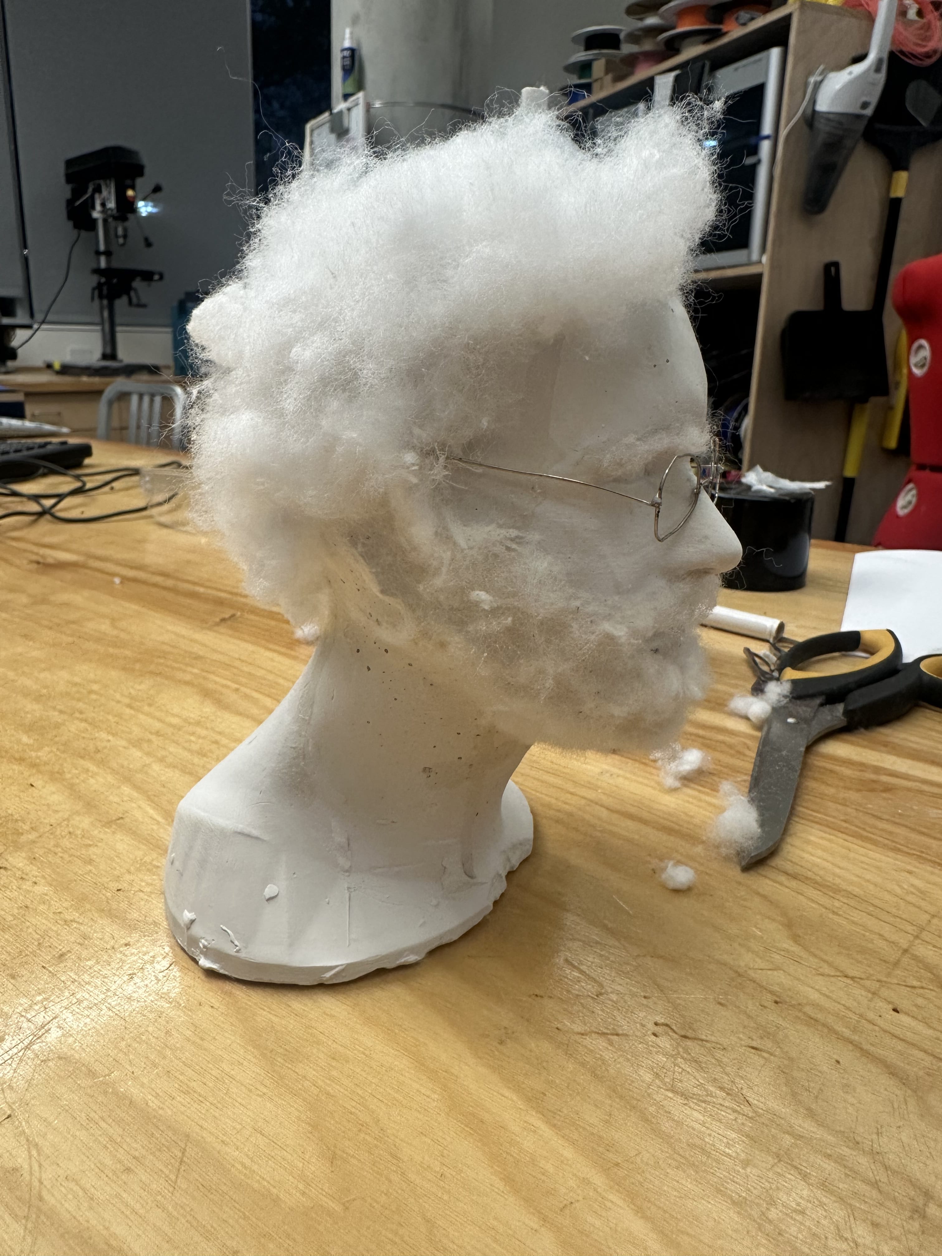
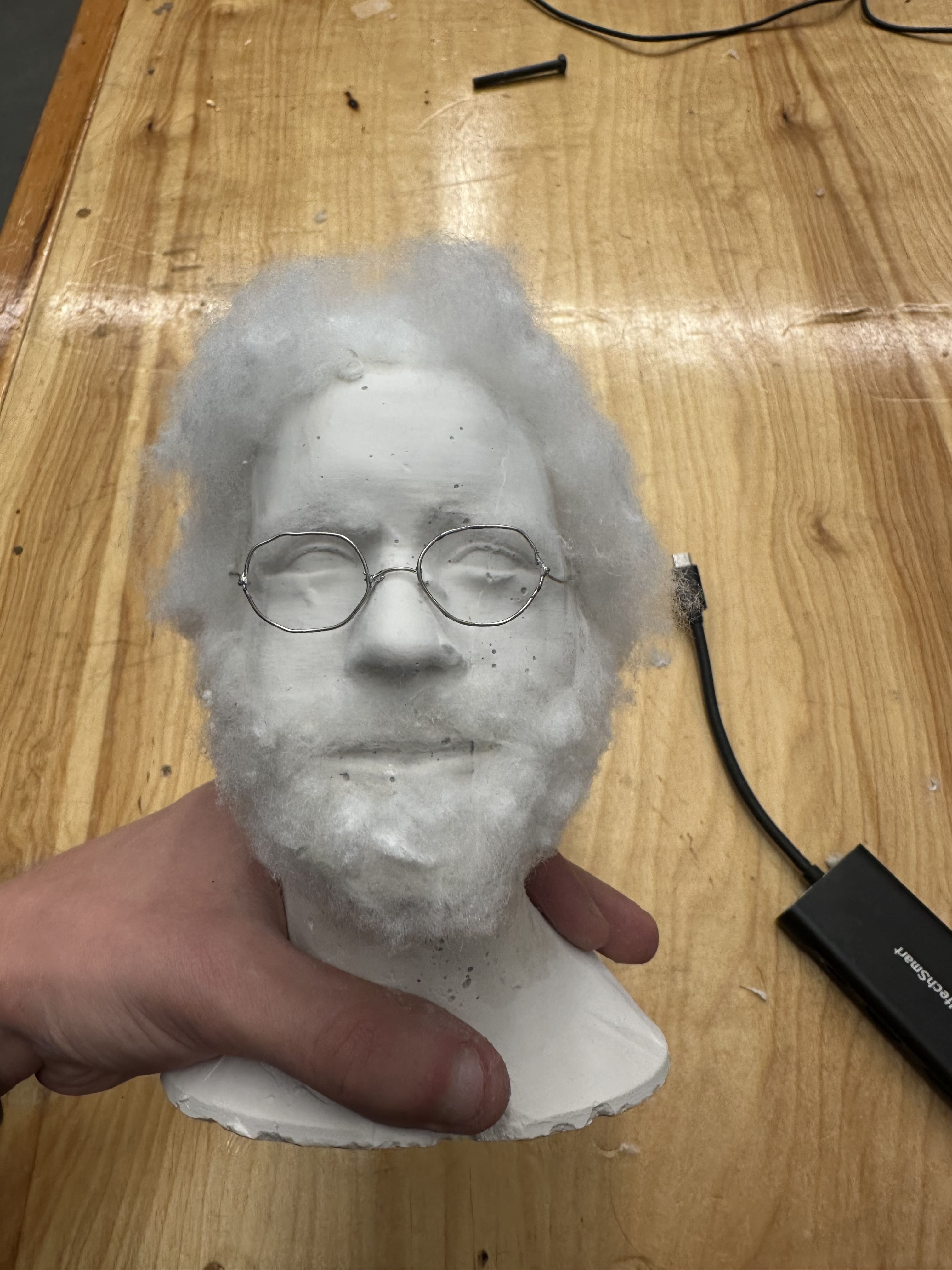
 Earlier in the semester Fan Xu made a 3D model of Neil’s head. I imported this into Bambu studio and printed it. It looked absolutely horrifying.
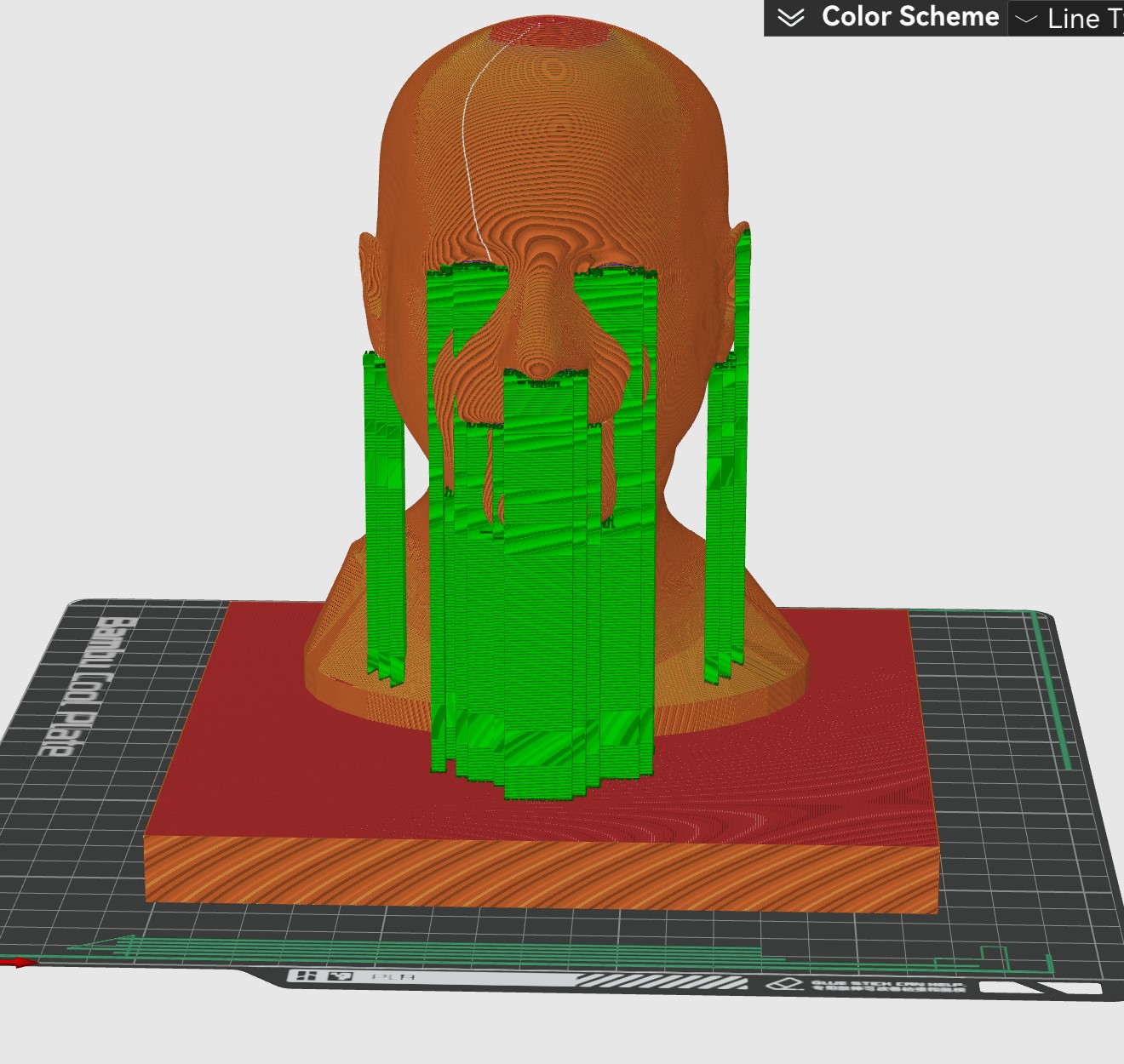
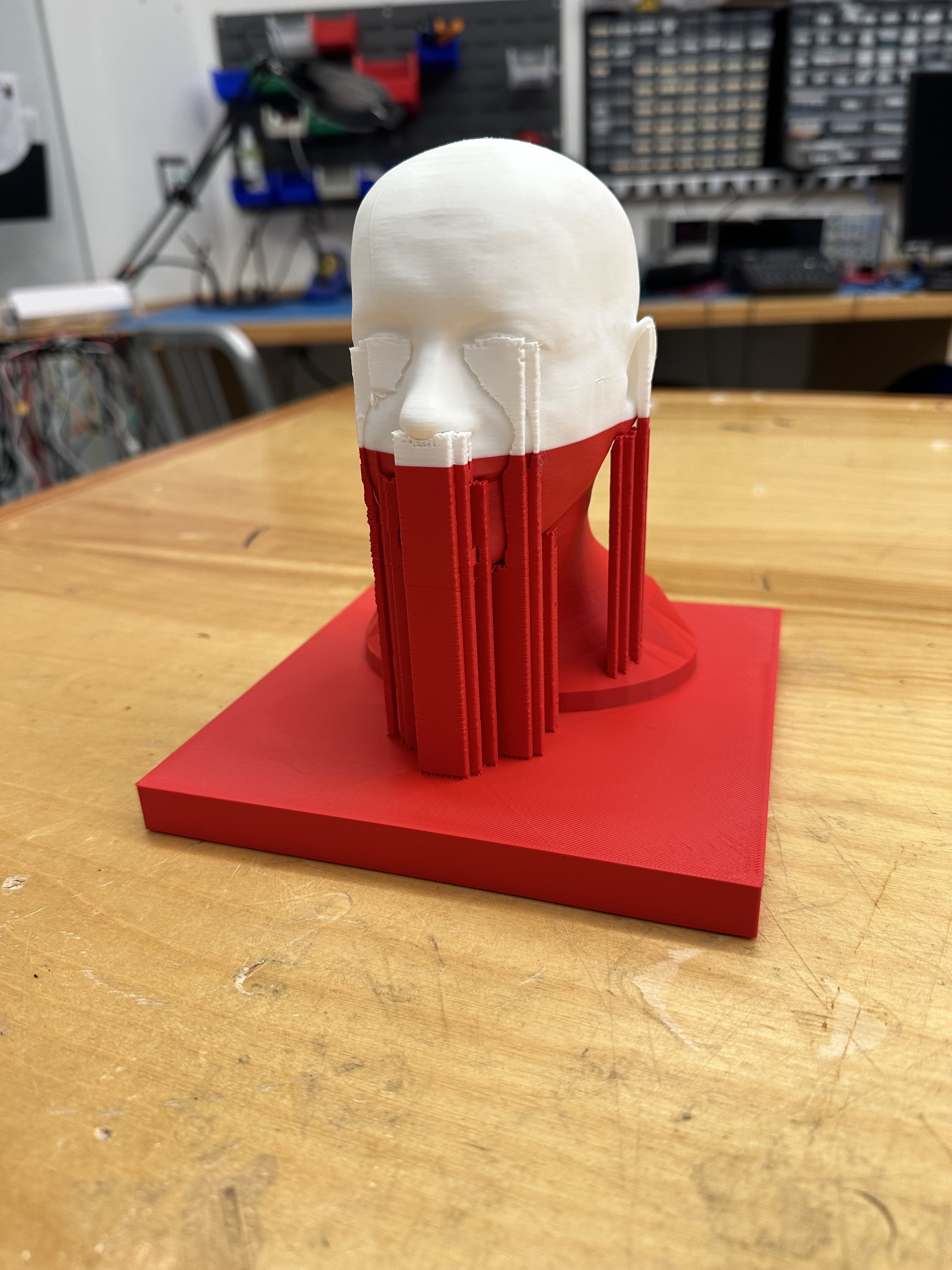
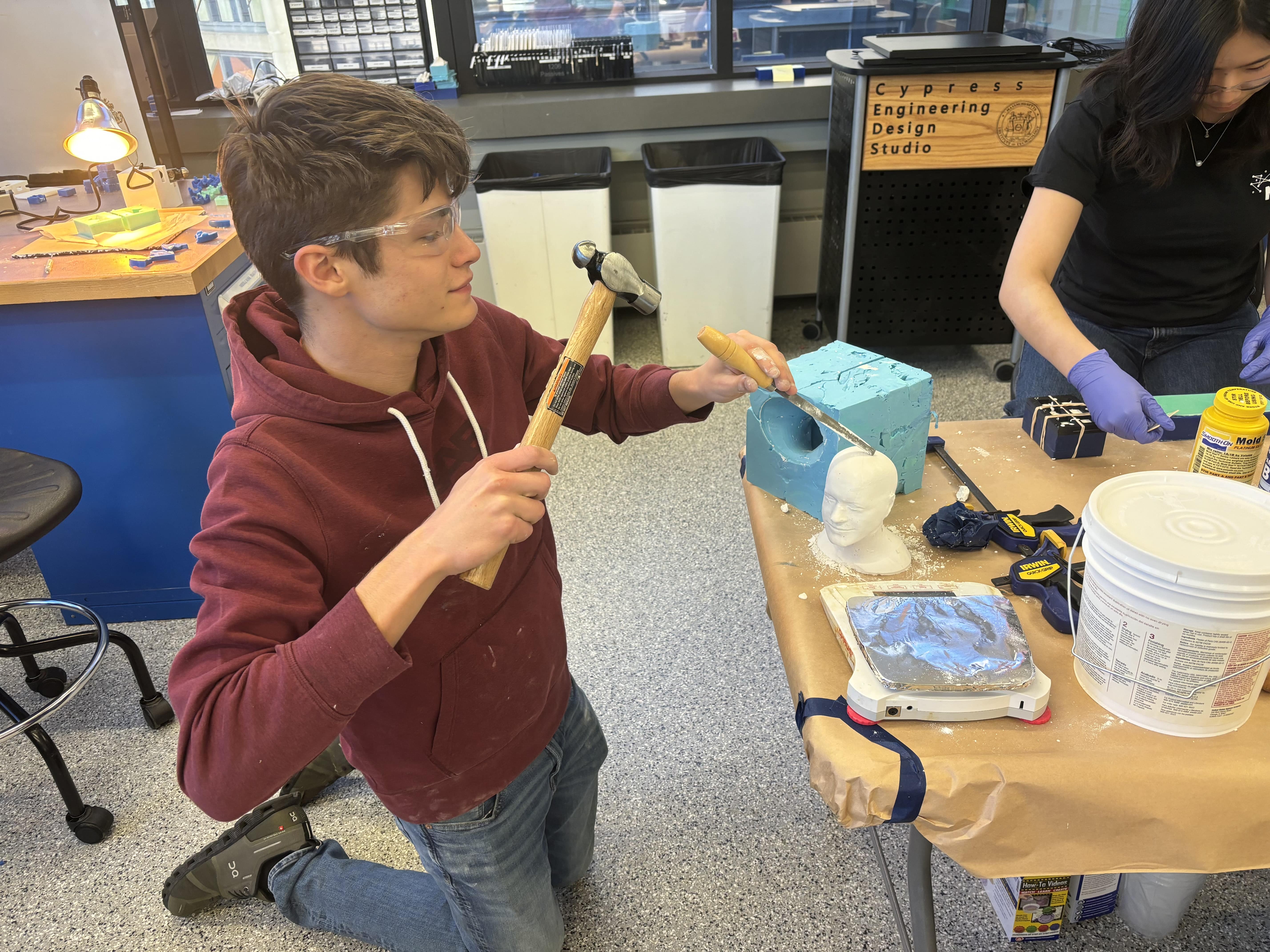
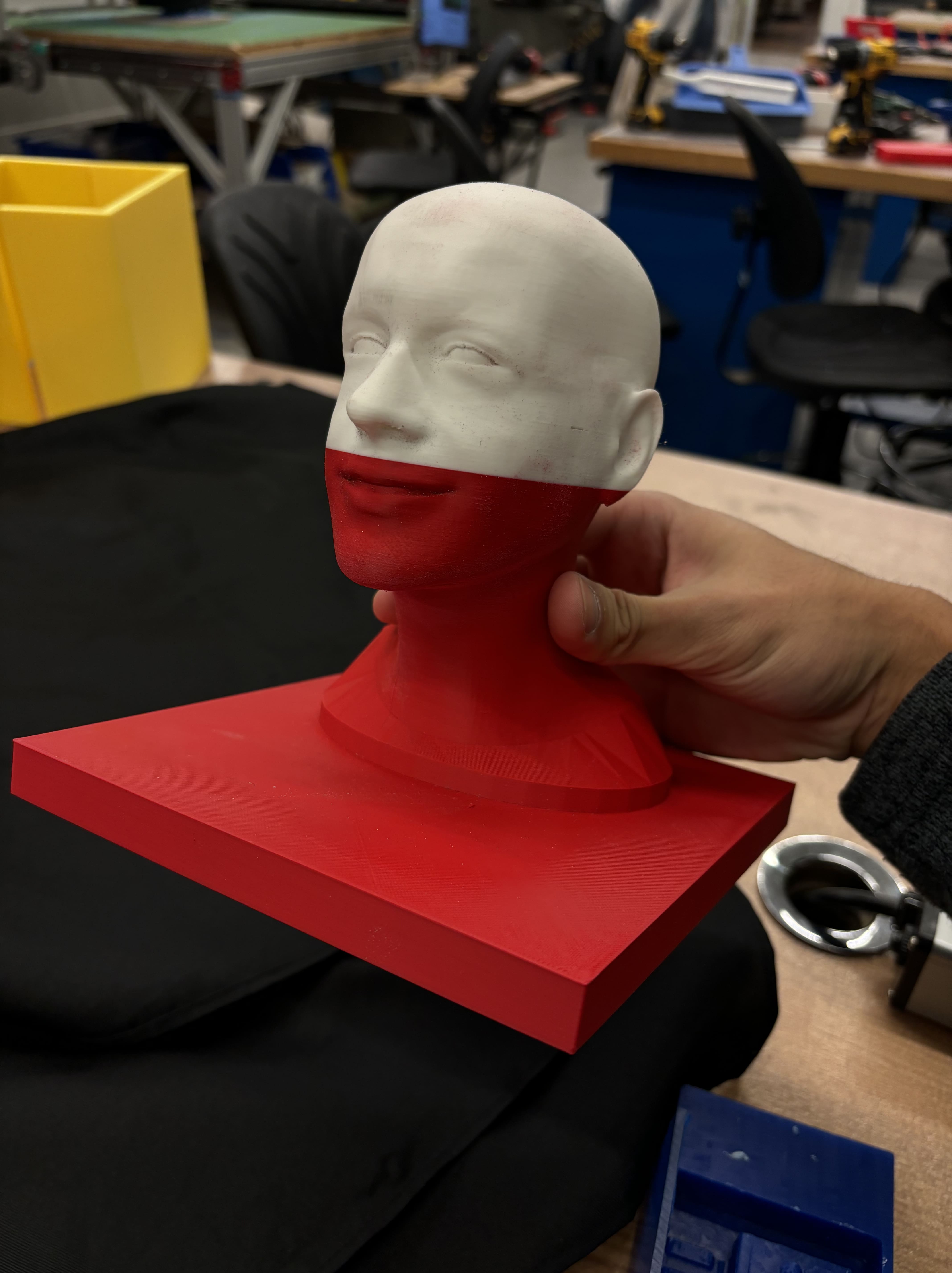 I then made a negative mold of this out of Oomoo and poured in some drystone.
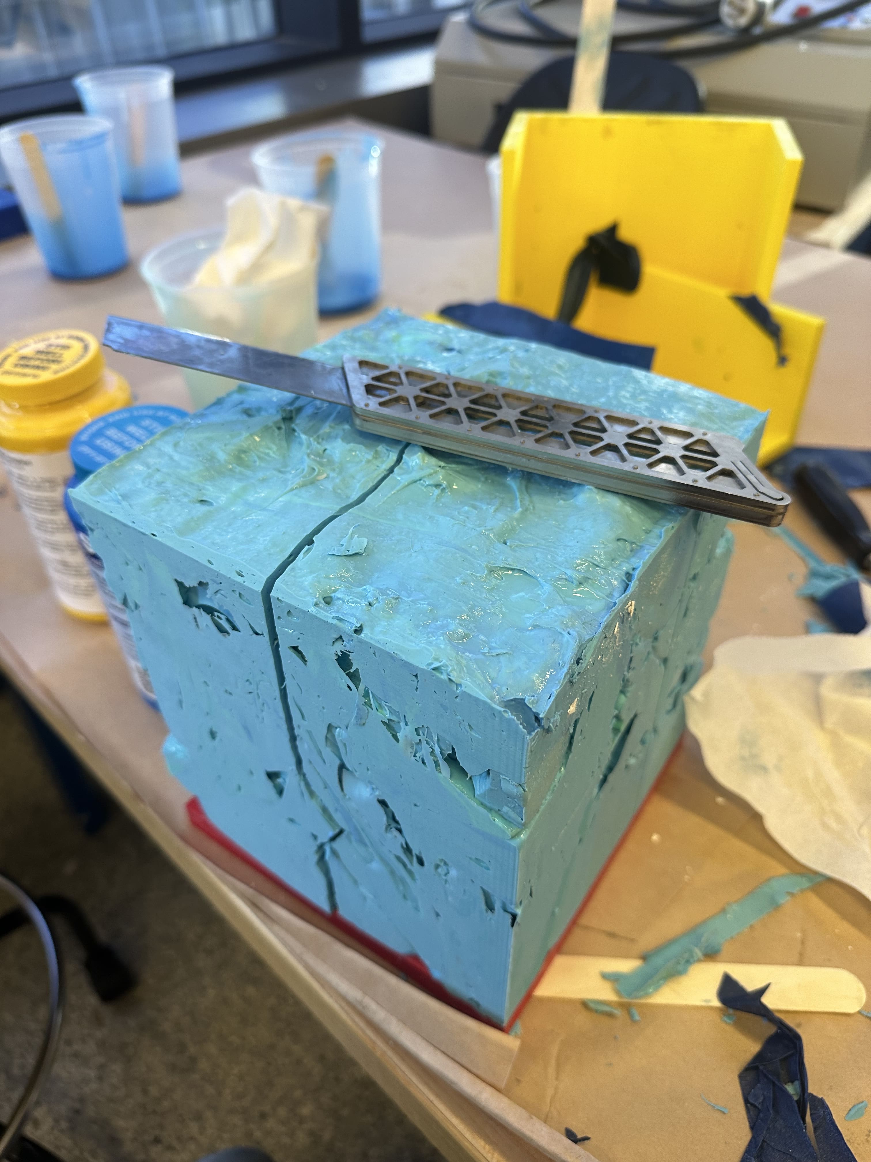 I cleaned it up with some post processing and pretended to be an artist.
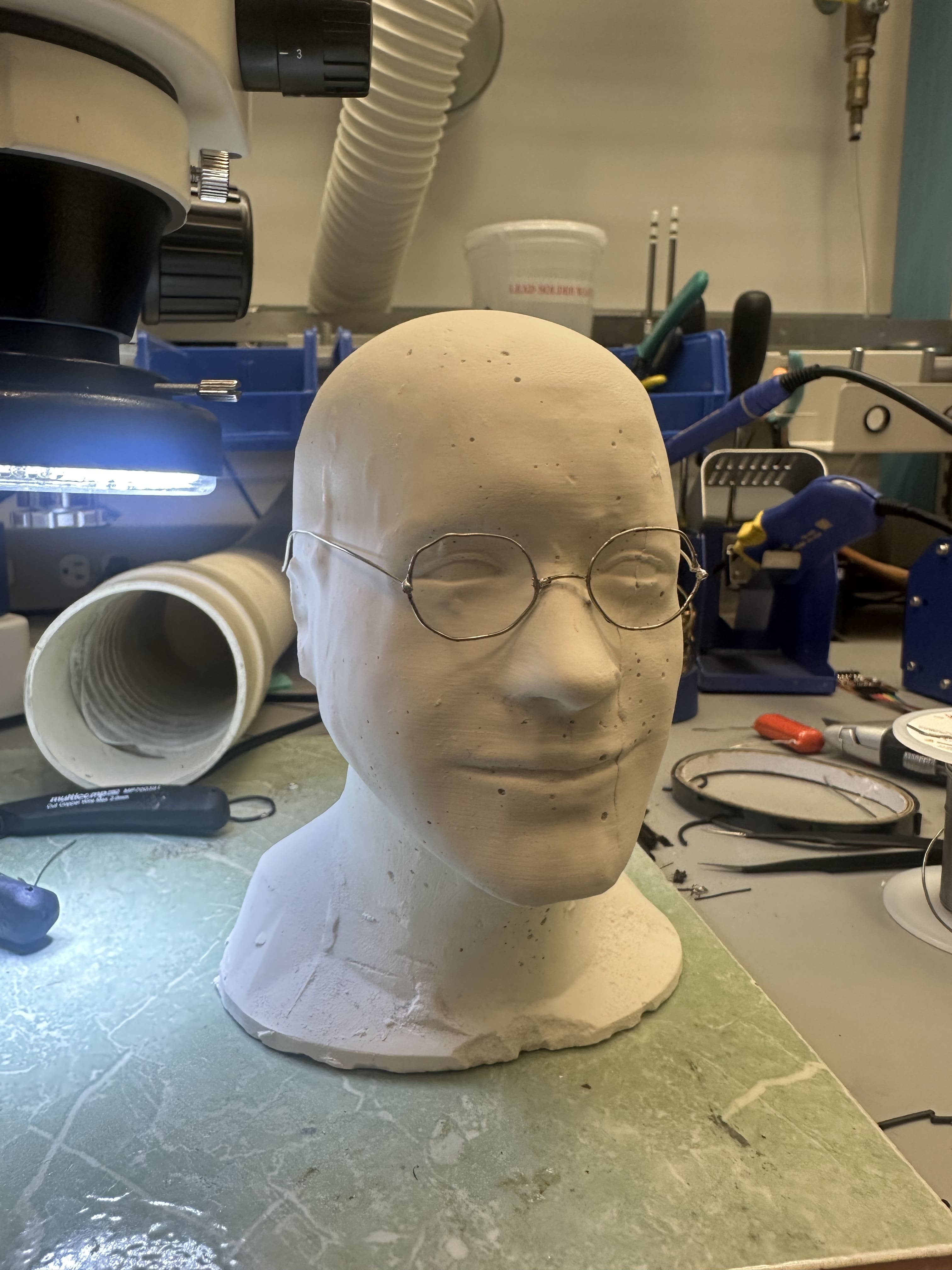
 I soldered some glasses out of some solid core wire.
Now I need some hair. If only there was a free source of white fibers…
 With the fibers obtained, now I got to style Neil’s hair. I used a spray on adhesive to attach the fibers to the drystone.
After a small haircut here is the final product. I’d say that looks like Neil! Now he’s ready to watch over all your games and remind you to go fast!
Final Product
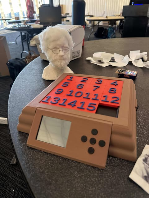
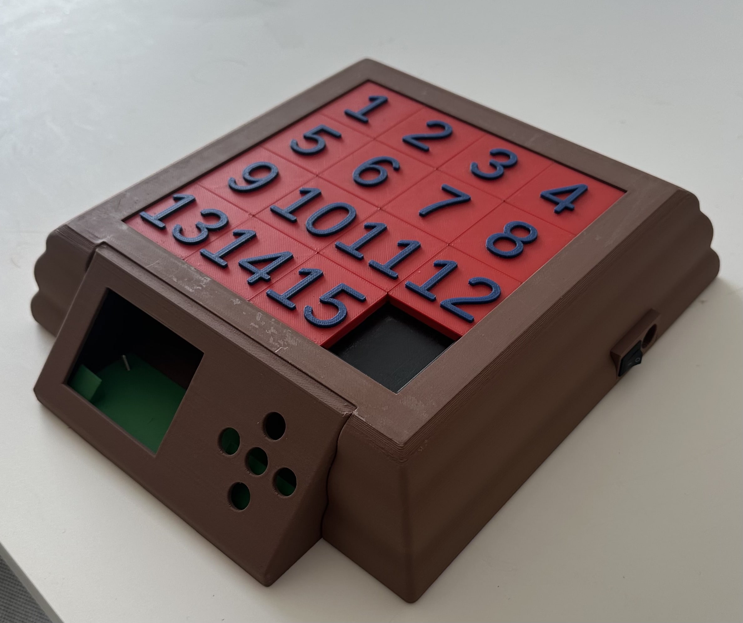
I am very happy with the final product. The packaging came out very nice and the sensing of the board worked exactly like I envisioned. It even passes the shake test: when I vigorously shake the device I do not hear any rattling!
The device also worked exactly how I envisioned socially. I got into a competition with people in my lounge to see who could solve it fastest!