Week 3: How to read 64 inputs with 7 pins - Sat, Sep 21, 2024
This week our assignment was to browse through the datasheet of a microcontroller and simulate a circuit with a microcontroller. I took this as the perfect opportunity to continue working on an idea I had in week 1: the interactive game of 15.
The ATTINY3226
I began by researching a potentially suitable microcontroller. While I love to prototype with Arduinos, I want to eventually phase them out of many of my future projects to get hands-on experience with embedded systems design. The makerspace has plenty of ATtiny3226 microcontrollers, so I thought that this would be a good starting point as any other microcontroller as the program I wanted to write is not computationally expensive. The data sheet provided me with these memory specs
| ATtiny3226 Memory | |
|---|---|
| Flash Memory | 32 KB |
| SRAM | 3 KB |
| EEPROM | 256 B |
| User Row | 32 B |
While this may not seem like much compared to a modern computer, it is more than enough for what I need. If you are clever, there is a lot you can do with only a little bit of memory. For instance, a lisp interpreter can surprisingly be encoded in less than 500 bytes!
Next I was interested in the input and output capabilities of the device. It looks like the chip has three ports that I saw in the Peripheral Address Map section.
| Base Address | Name | Description |
|---|---|---|
| 0x0400 | PORTA | Port A Configuration |
| 0x0000 | VPORTA | Virtual Port A |
| 0x0420 | PORTB | Port B Configuration |
| 0x0004 | VPORTB | Virtual Port B |
| 0x0440 | PORTC | Port C Configuration |
| 0x0008 | VPORTC | Virtual Port C |
I didn’t know if I should be using the port itself or the virtual port, but I read in I/O Pin Configuration I read " Access to the Virtual PORT registers has the same outcome as access to the regular registers but allows for memory specific instructions, such as bit manipulation instructions, which cannot be used in the extended I/O Register space where the regular PORT registers reside." Therefore I should use the address of the virtual ports. I should be able to read inputs at these addresses using some code that looks something like this:
#define PORTA = *(volitile int 0x0000)
#define PORTB = *(volitile int 0x0004)
#define PORTC = *(volitile int 0x0008)
byte read_port_bit(int port, byte bit_pos) {
return port>>bit_pos & 1;
}
void write_port_bit(int port, byte bit_pos, byte bit) {
port = (port & ~(1 << bit_pos)) | (bit << bit_pos)
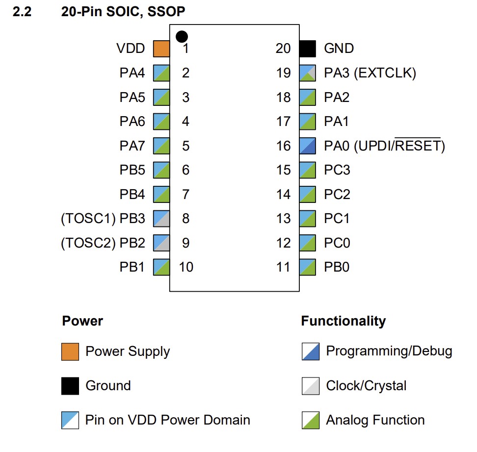
}I looked a little bit deeper into I/O configuration and was happy to see that I have 18 GPIO pins at my disposal all with configurable pullup resistors and interrupts. I can configure all the pins to be either outputs or inputs using the data direction variable for my port at the VPORTx.DIR register.
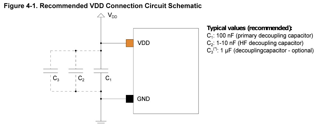
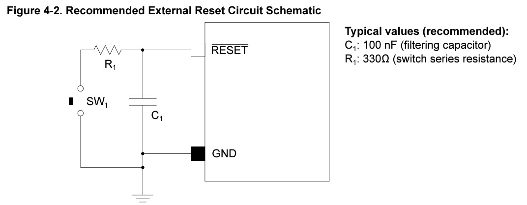
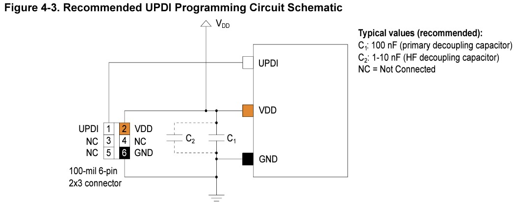
As for the physical circuit, the ATtiny3226 that I am using comes in a 20 pin SOIC configuration. The data sheet recommends an input voltage between 1.8 and 5.5v. The data sheet also provided helpful figures for connecting the microcontroller to power, connecting a reset button, and connecting a UPDI programmer.
Designing the Game of 15 Circuit
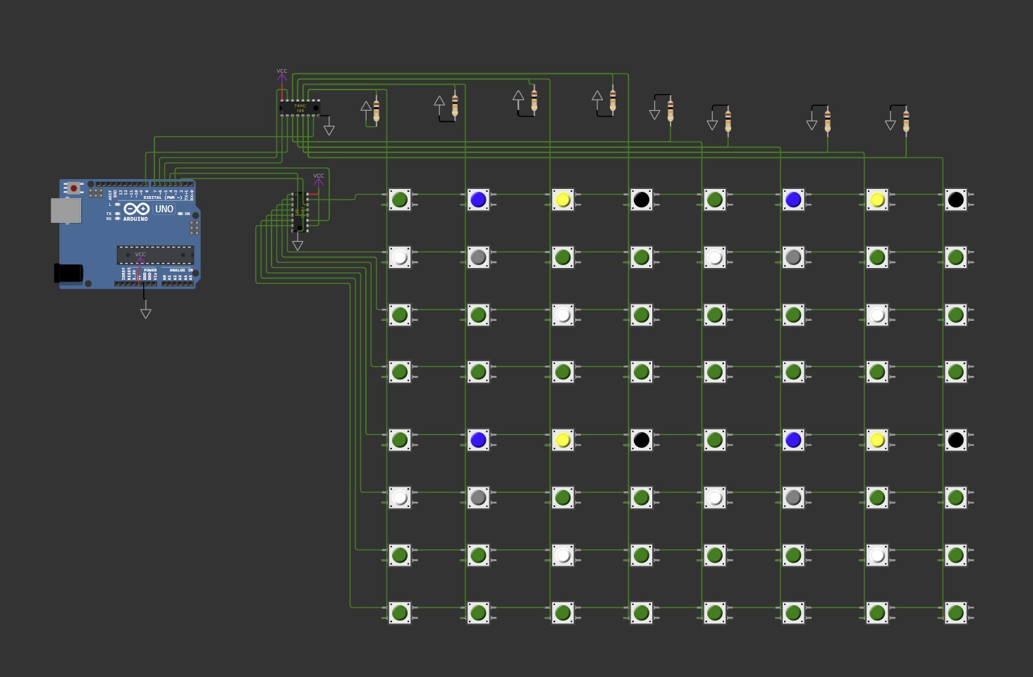
The main challenge of this project is reading the input from 64 hall effect sensors to get the board position. I began by considering using 8 74HC165 shift in registers to shift in the state of all 64 hall effect sensors with only 4 pins on an arduino board. While this would have worked, when I was talking to Yuval in EDS, he recommended multiplexing the inputs. This would greatly simplify the wiring at the cost of only a couple more pins used on the Arduino, so I opted for this circuit.
I used Wokwi to simulate my circuit that you can check out here. The buttons represent each of the AH3144E hall effect sensors I will use as their output seems to be either floating or connected to their VCC pin depending on the magnetic field present. (UPDATE: I realized that these hall effect sensors have a schmitt trigger in them that either leaves the output pin floating or connected to ground. This was an easy fix as I just swapped out all the pull down resistors for pull up resistors.)
The process of reading the board was very simple with this setup as I could just multiplex each row and read in the column data and put it in a data type board that I defined to be an array of 8 bytes.
void read_board(Board* b) {
  for (byte i = 0; i < n_rows; i++) {
    // Activate the output row on 74HC595
    writeShiftRegister_595(1 << i);
    // Read the input from 74HC165 for that row
    (*b)[i] = readShiftRegister_165();
  }
}
Decoding the board into an array of where the pieces are was not much of a challenge either. I encoded each piece such that the LSB was in the upper left corner and the MSB was in the lower right corner.
void decode_board(Board* b, Decoded_Board* d) {
  for(byte i = 0; i < n_rows/2; i++) {
    for(byte j = 0; j < n_cols/2; j++) {
      byte raw =  (1&(*b)[2*i]>>(2*j))<<0 |
                    (1&(*b)[2*i]>>(2*j+1))<<1 |
                    (1&(*b)[2*i+1]>>(2*j))<<2 |
                    (1&(*b)[2*i+1]>>(2*j+1))<<3;
      (*d)[i][j] = 15 - raw;
    }
  }
}Neopixel Correctness Color
To show the user their progress and signify a completed puzzle, I opted to use a 5mm wide neo pixel strip. I had a lot of fun coming up with functions to display the correct color depending on how many tiles the user has in the correct position. I used the polynomials from a quadratic Bézier curve to interpolate between all the neo pixels being red for 0/15 and green for 15/15. If you would like to see what this looks like I made a simple desmos 3D graph of the curve in color space interpolating from red to green here.
This would be great if I wanted to have the strand be a single color, but I would also like to make the lights dynamic. I acheived an undulating effect by multiplying the colors for each neopixel by a sine wave that moves as time goes on. You can play with the functions I used here.
// Timing and offset for wave animation
unsigned long lastUpdateTime = 0; // Keeps track of the last time the animation updated
int waveOffset = 0; // Current phase offset for the wave animation
// Parameters for the idle animation in show_correct function
#define WAVE_AMPLITUDE 0.5 // Magnitude of distortion in the sine wave
#define WAVE_NUMBER 1 // Wave number, controls spatial frequency of the sine wave
#define WAVE_VELOCITY 100 // Time between wave updates in milliseconds
void show_correct(float correct, float total) {
// Update the wave offset based on the time and wave velocity
if (millis() - lastUpdateTime >= WAVE_VELOCITY) {
lastUpdateTime = millis();
waveOffset++;
// Reset the offset when it exceeds the number of pixels
if (waveOffset >= strip.numPixels()) {
waveOffset = 0;
}
}
// Calculate the normalized correct value
float normalizedCorrect = correct / total;
// Loop through each pixel and update its color based on a quadratic Bézier curve with sine wave distortion
for (int i = 0; i < strip.numPixels(); i++) {
float red = pow(1 - normalizedCorrect, 2) * (1 + WAVE_AMPLITUDE * sin(WAVE_NUMBER * (i + waveOffset))) * 255;
float green = pow(normalizedCorrect, 2) * (1 + WAVE_AMPLITUDE * sin(WAVE_NUMBER * (i - waveOffset))) * 255;
float blue = 2 * normalizedCorrect * (1 - normalizedCorrect) * (1 + WAVE_AMPLITUDE * sin(WAVE_NUMBER * i)) * 255;
// Clip the RGB values to the 0-255 range
byte clippedRed = max(0, min(255, red));
byte clippedGreen = max(0, min(255, green));
byte clippedBlue = max(0, min(255, blue));
strip.setPixelColor(i, clippedRed, clippedGreen, clippedBlue);
}
strip.show();
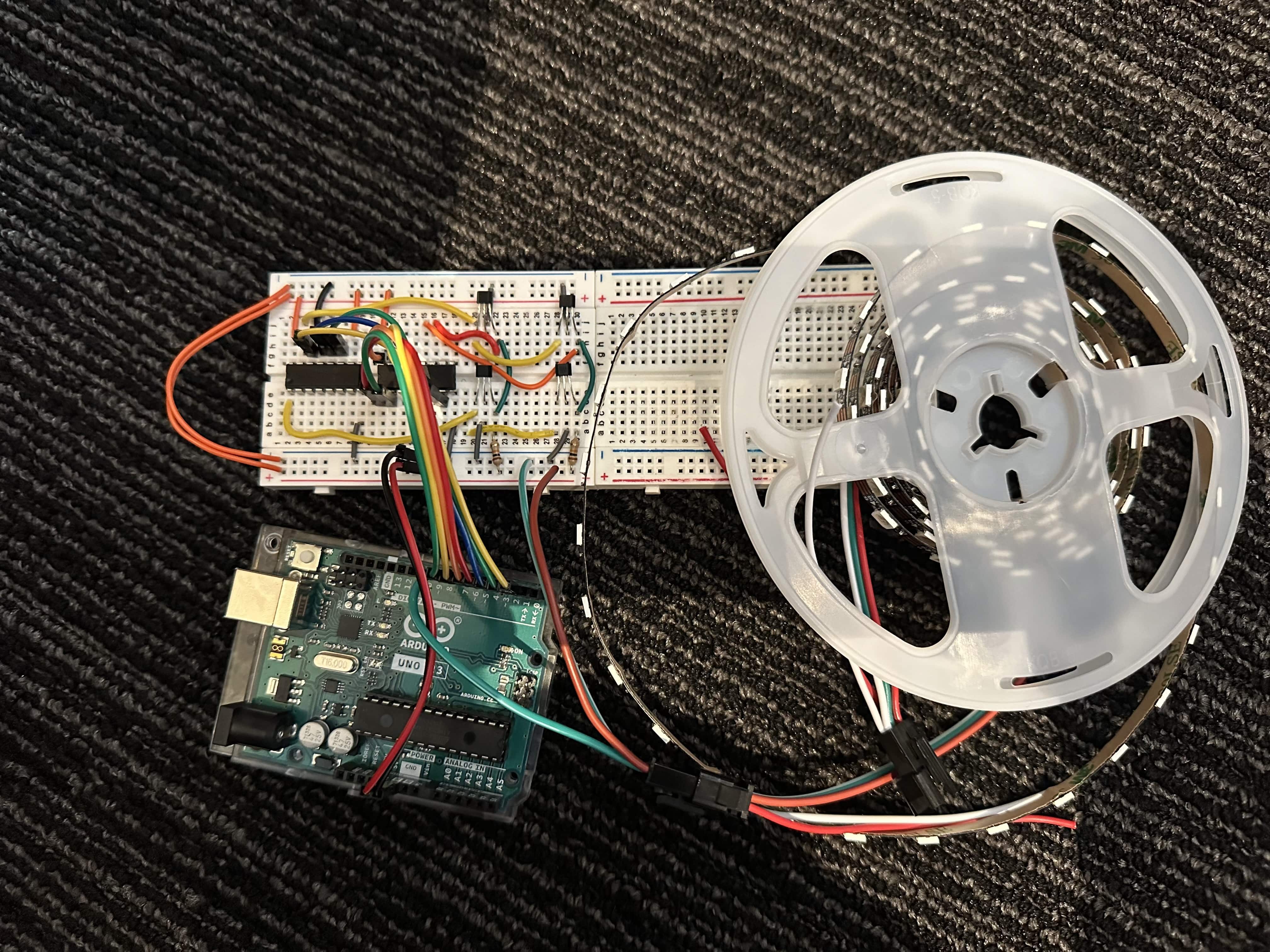
}Breadboard Prototyping
I had enough time this week to test out a small version of the circuit. Instead of 64 hall effect sensors I used 4 to be able to read in one piece of the puzzle. To test the neopixels I ran the show_correct function based on what number the sensors read in.
![]()
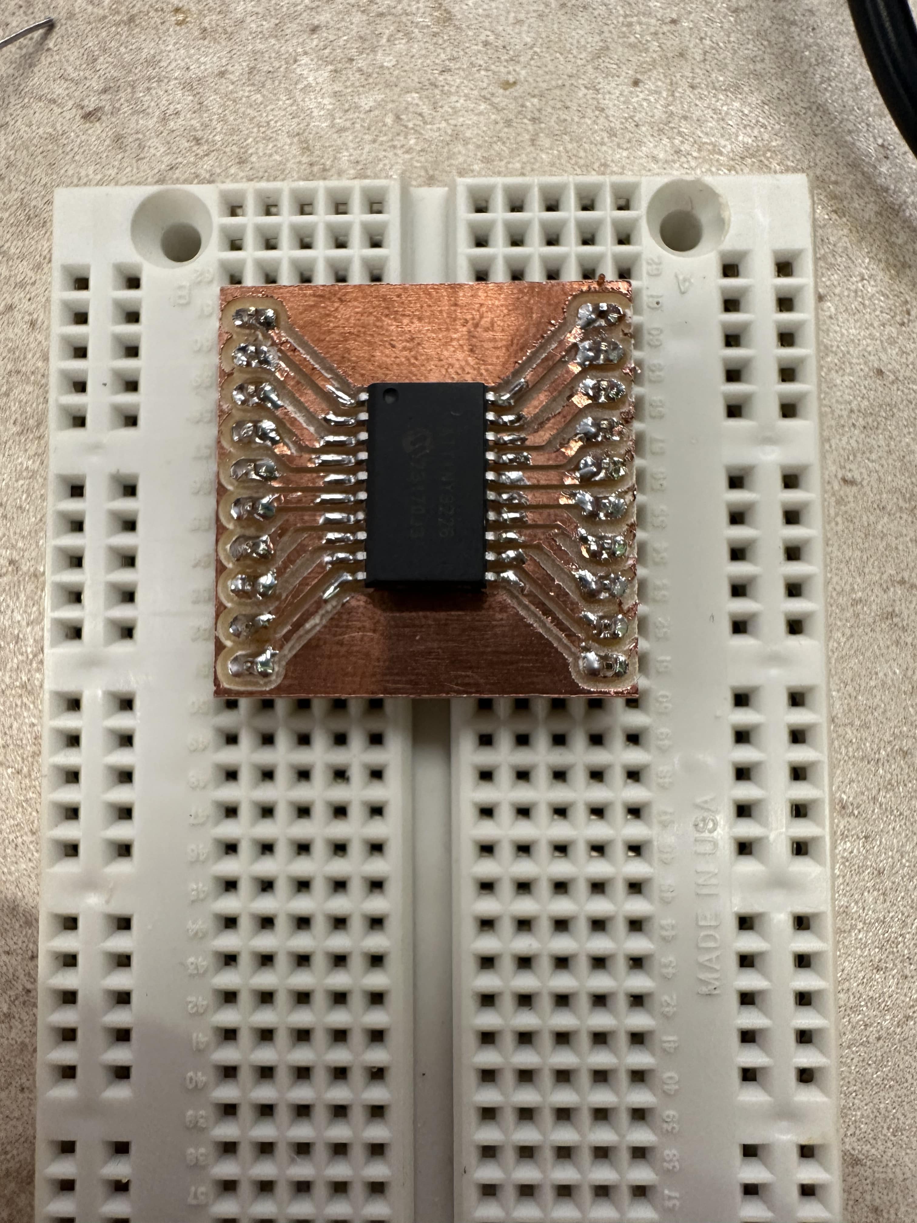
Bonus: Board Milling
As much as I love how easy the Arduino dev boards are to use, I hate to use them in final projects. Therefore I will be programming a microcontroller IC on a circuit I designed for this class. In order to prototype, I designed some breakout boards for the ATTINY412, ATTINY3226, and SAMD11. The gerber files can be found on my github.
 I also tried to mill out a board for the hall effect sensor grid. Unfortunately this board could not fit in the mill that I did the breakout boards on, so I had to use the Roland mill, which runs on mods and does not take gerber files. I spent many hours trying to convert my kicad project into png files, and had to do a back copper pour in order to get the holes correct for drilling out holes for the hall effect sensors. After doing this I was very excited to press “start” on the machine. Maybe I was a little excited to press start, because when I came back to my board I realized that the cutout was inverted and my board that took hours to mill was useless. Damnit!
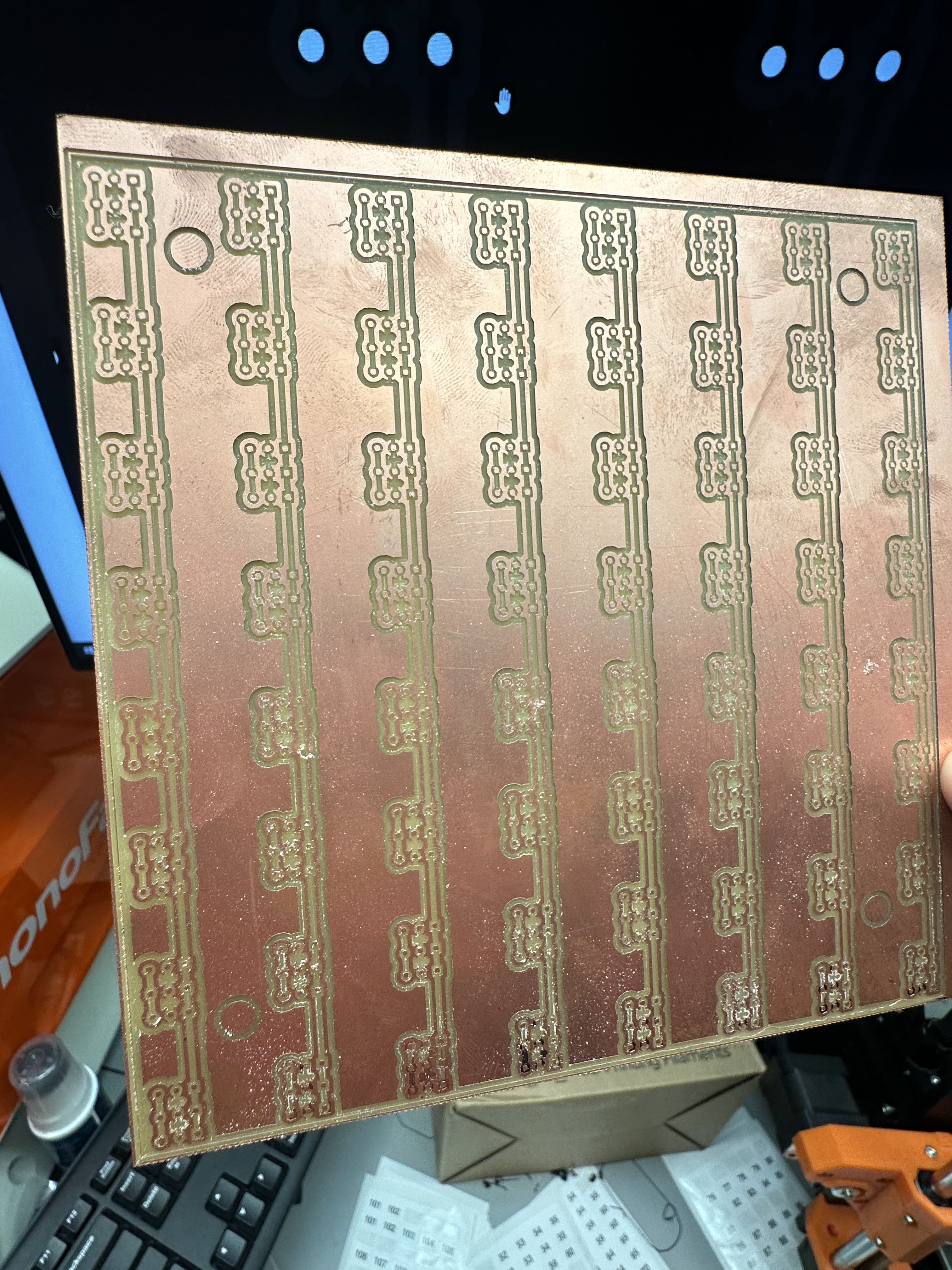 I should have ordered this board from a PCB manufacturer, but due to a sunk cost fallacy, I will get this board milled out!