Week 5: How to make a parametric PCB - Wed, Oct 9, 2024
This week our assignment was to design a development board to interact and communicate with an embedded microcontroller. As a 6.2 major, I found myself in familiar territory. In order to challenge myself and grow my maker toolkit, I decided that I want to do this assignment only using a hardware description language to program my board layout and routing rather than doing it manually on Kicad.
I often find the process of laying out a PCB in CAD tedious, and I feel like I have little control over the geometric constraints between the components on my board. I think it would be great if there existed a PCB design software that implemented basic constraint solving between the footprints of components. With simple length constraints, angle constraints, linear patterns, circular patterns, tangency constraint, and some splines, I feel like the process of board layouts could be easier and more precise than ever. This led me to ask if such a software existed in lecture, and I learned that one of the TAs in the class, Leo McElroy, is working on that right now! He made a software called “SVG-PCB” that allows you to both graphically place footprints, and also program the placement of the footprints using a hardware description language in java script.
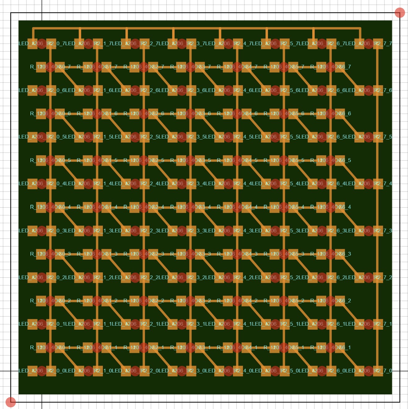
I began by making a function that could create an LED grid given the dimensions of the grid and the distance between leds. I had to include many 0 ohm resistors to jump the vertical wires connecting the cathodes of the LEDs in each column, and I feel like manufacturing this board would be extremely tedious.
function make_grid(x_size, y_size, delta, trace_thickness) {
  const outline = path(
    [-delta * 0.5, (y_size - 0.5) * delta],
    [(x_size - 0.5) * delta, (y_size - 0.5) * delta],
    [(x_size - 0.5) * delta, -delta * 0.5],
    [-delta * 0.5, -delta * 0.5],
  );
  board.addShape("outline", outline);
  let leds = []
  let resistors = []


  //Place components
  for (let x = 0; x < x_size; x += 1) {
    for (let y = 0; y < y_size; y += 1) {
      // Create each LED object and push it into the leds array
      const led = board.add(LED_1206, {
        translate: pt(x * delta, y * delta),
        rotate: 0,
        id: "LED_1206_IP2_" + String(x) + "_" + String(y)
      });
      leds.push(led); // Store the LED object in the array
      if (x < x_size - 1 && y > 0) {
        const resistor = board.add(R_1206, {
          translate: pt(x * delta + 0.055, (y - 0.5) * delta),
          rotate: 0,
          id: "R_1206_4OG" + String(x) + "_" + String(y)
        })
        resistors.push(resistor)
      }
    }
  }
  //Place vertical wires
  for (let x = 0; x < x_size; x += 1) {
    for (let y = 0; y < y_size - 1; y += 1) {
      board.wire(
        path(leds[x * y_size + y].pad("C"), leds[x * y_size + y + 1].pad("C"), ),
        trace_thickness
      );
    }
  }
  for(let x = 0; x < x_size -1; x++) {
    for(let y = 0; y < y_size-1; y++) {
        if(x < x_size - 2) {
      board.wire(
          path(resistors[x * (y_size-1) + y].pad("2"), resistors[(x+1) * (y_size-1) + y].pad("1"), ),
        trace_thickness
      );
        }
      board.wire(
          path(resistors[x * (y_size-1) + y].pad("2"), leds[(x+1)*y_size+y].pad("A"), ),
        trace_thickness
      );
    }
  }
  for(let x = 0; x < x_size-1; x++) {
    board.wire(
            path(leds[x * y_size + y_size-1].pad("A"),
                 [leds[x * y_size + y_size-1].pad("A")[0], leds[x * y_size + y_size-1].pad("A")[1]+0.1],
                 [leds[(x+1) * y_size + y_size-1].pad("A")[0], leds[(x+1) * y_size + y_size-1].pad("A")[1]+0.1],
                 leds[(x+1) * y_size + y_size-1].pad("A"), ),
        trace_thickness
      );
  }
}
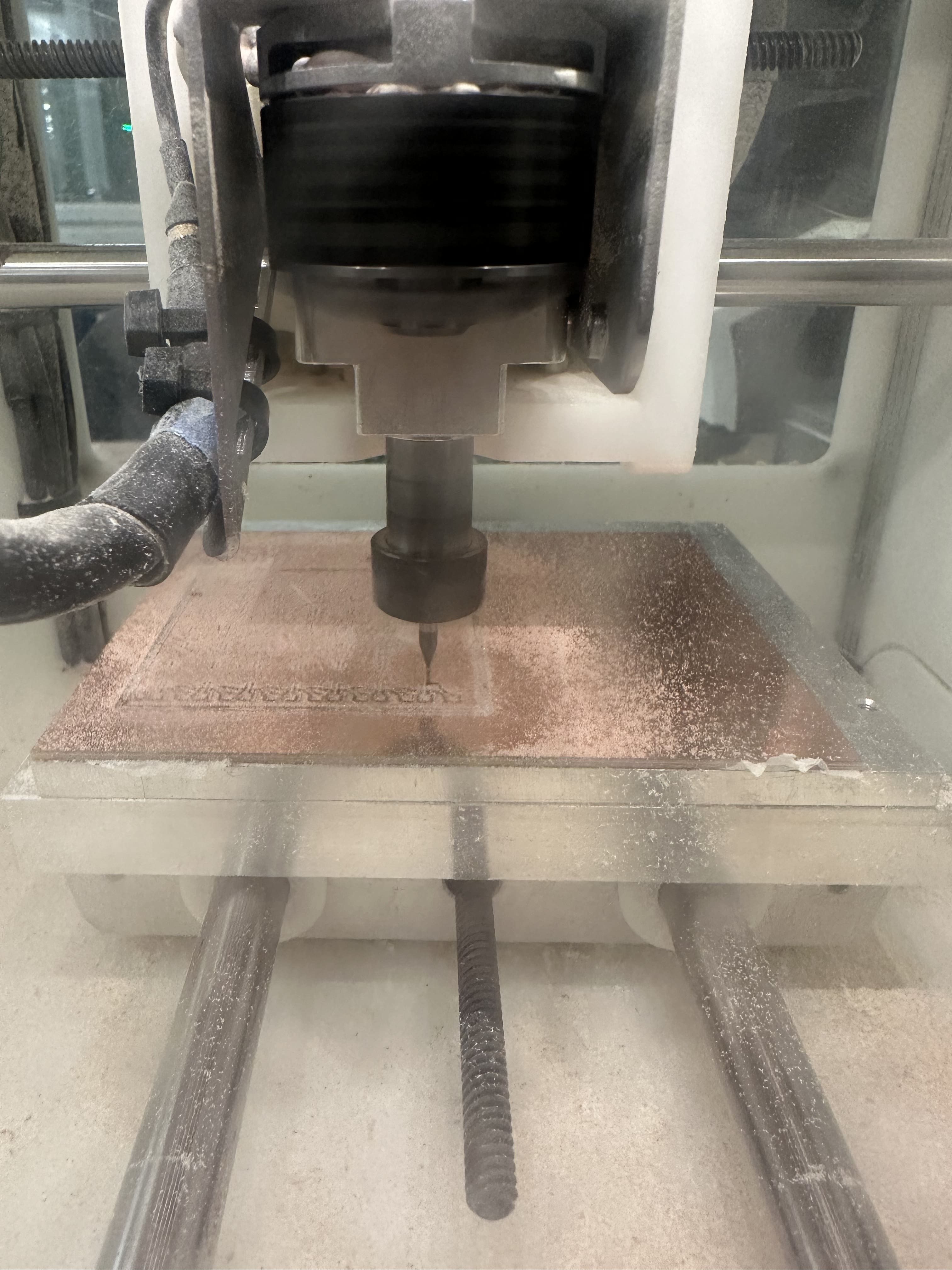
After this I decided to make a function to parametrically create led circles
function make_circular_pattern(center, radius, led_num, trace_width) {
  let ID = Math.floor(Math.random()*300)
  let angle = 2*Math.PI/led_num
  for (let i = 0; i < led_num; i++) {
    const LED = board.add(LED_1206, {
      translate: pt(center[0] + radius*Math.cos(angle*i), radius*Math.sin(angle*i)),
      rotate: 360*i/led_num,
      id: "LED_1206_" + String(i) + "_" +  String(ID)
    })
    leds.push(LED)
  }


  for (let i = 0; i < led_num; i++) {
    board.wire(
        path(leds[i].pad("C"), leds[(i+1) % led_num].pad("C"), ),
        trace_width
      );
    board.wire(
        path(leds[i].pad("A"), leds[(i+1) % led_num].pad("A"), ),
        trace_width
      );
  }
}
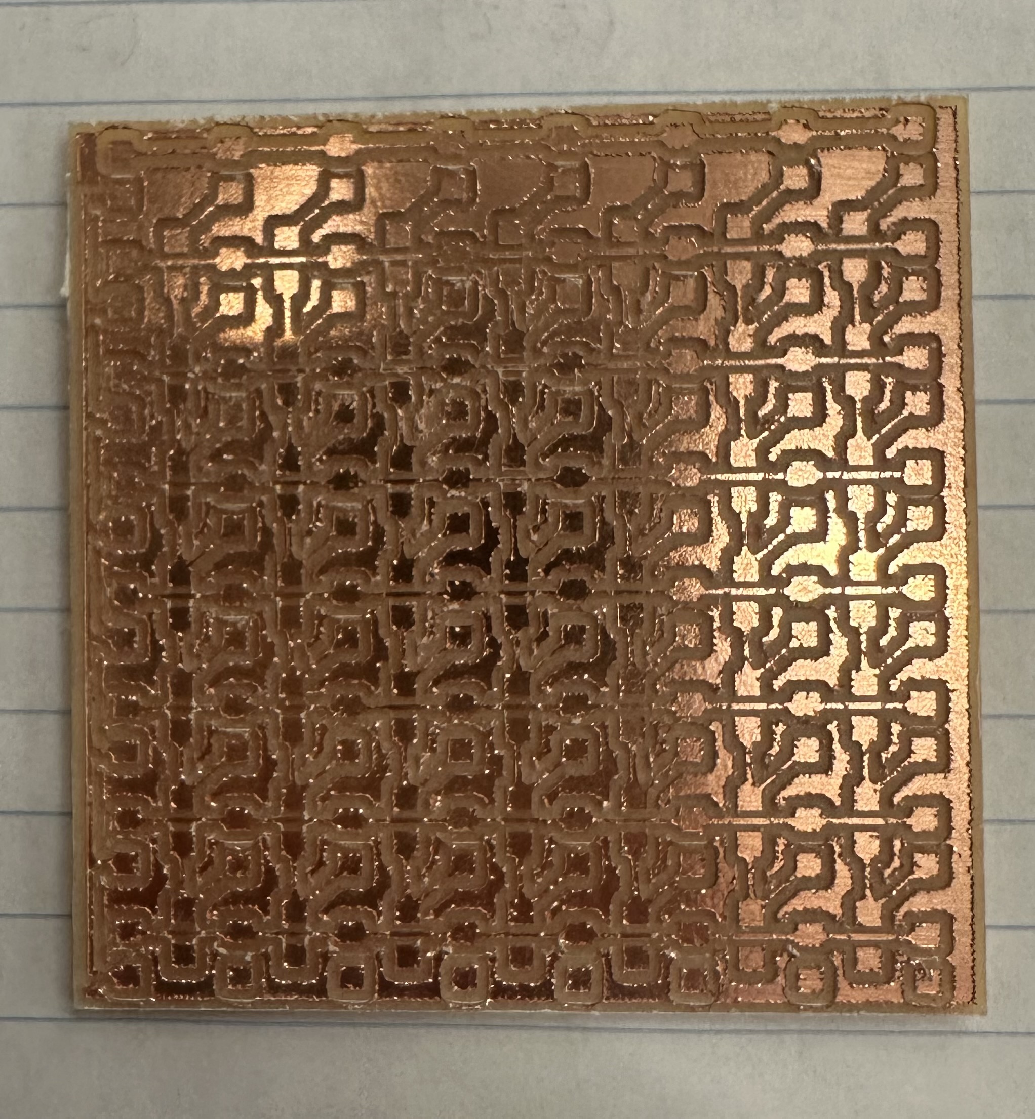
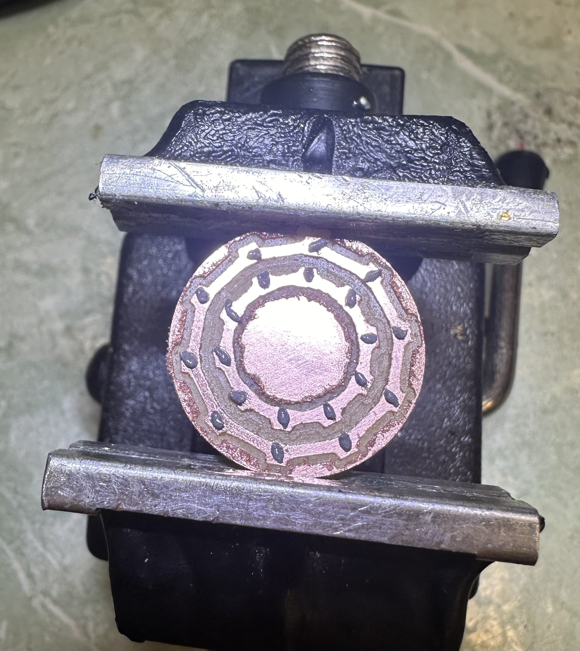
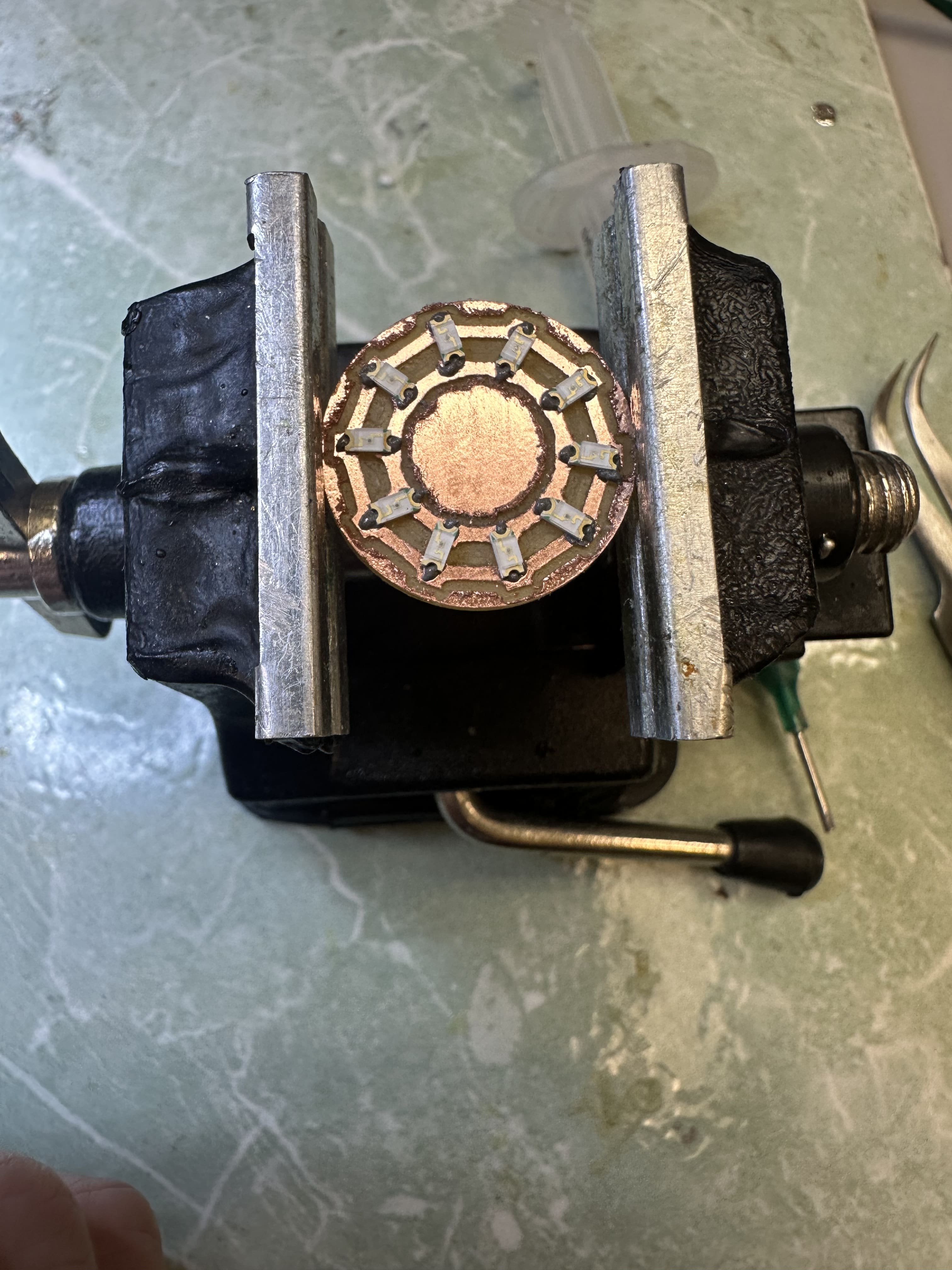
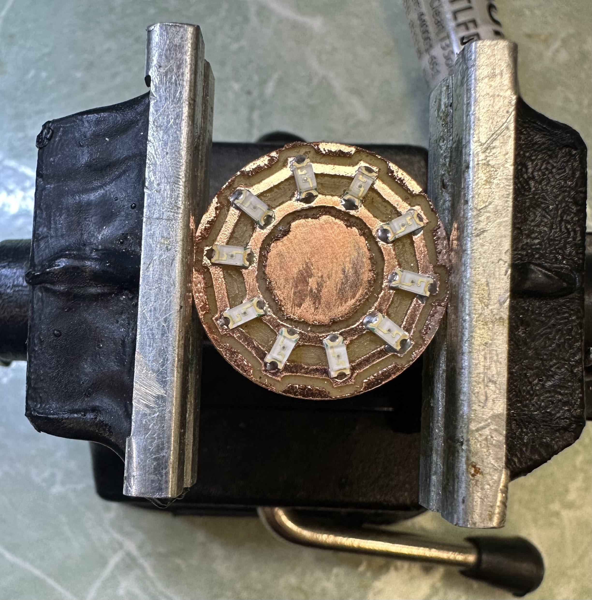
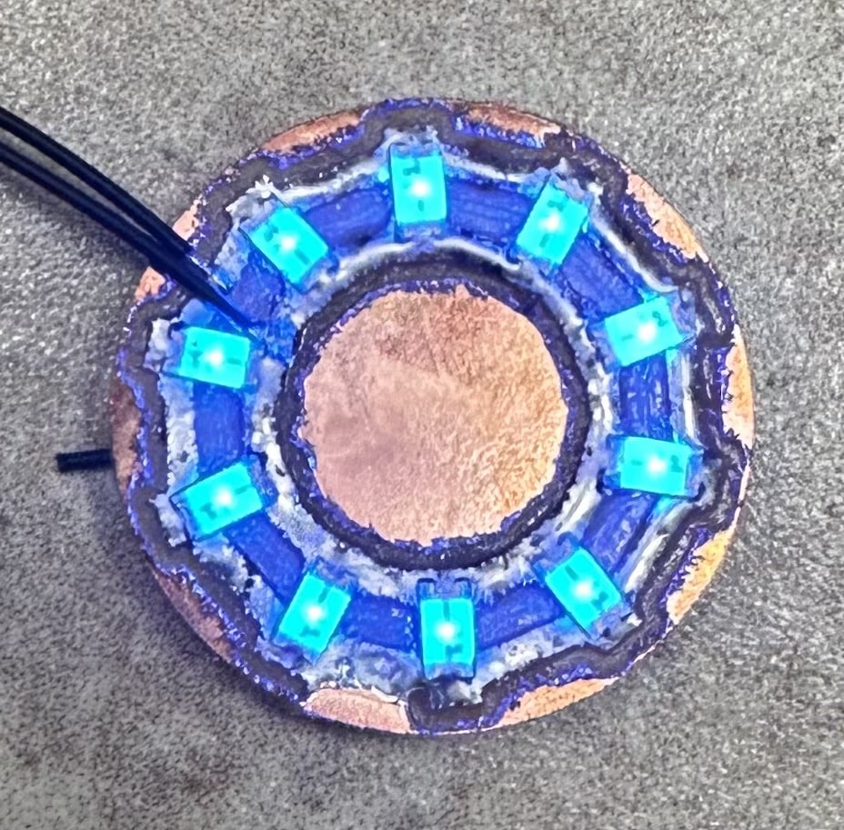
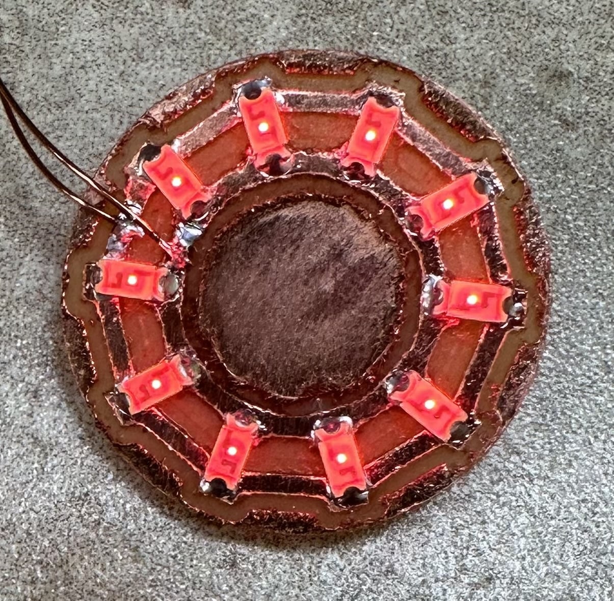
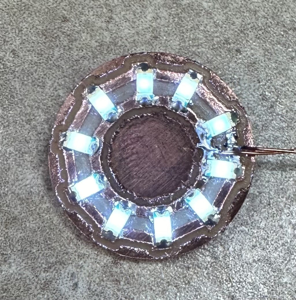
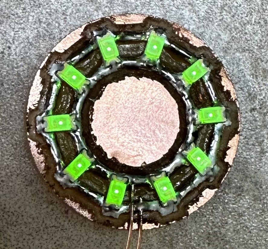
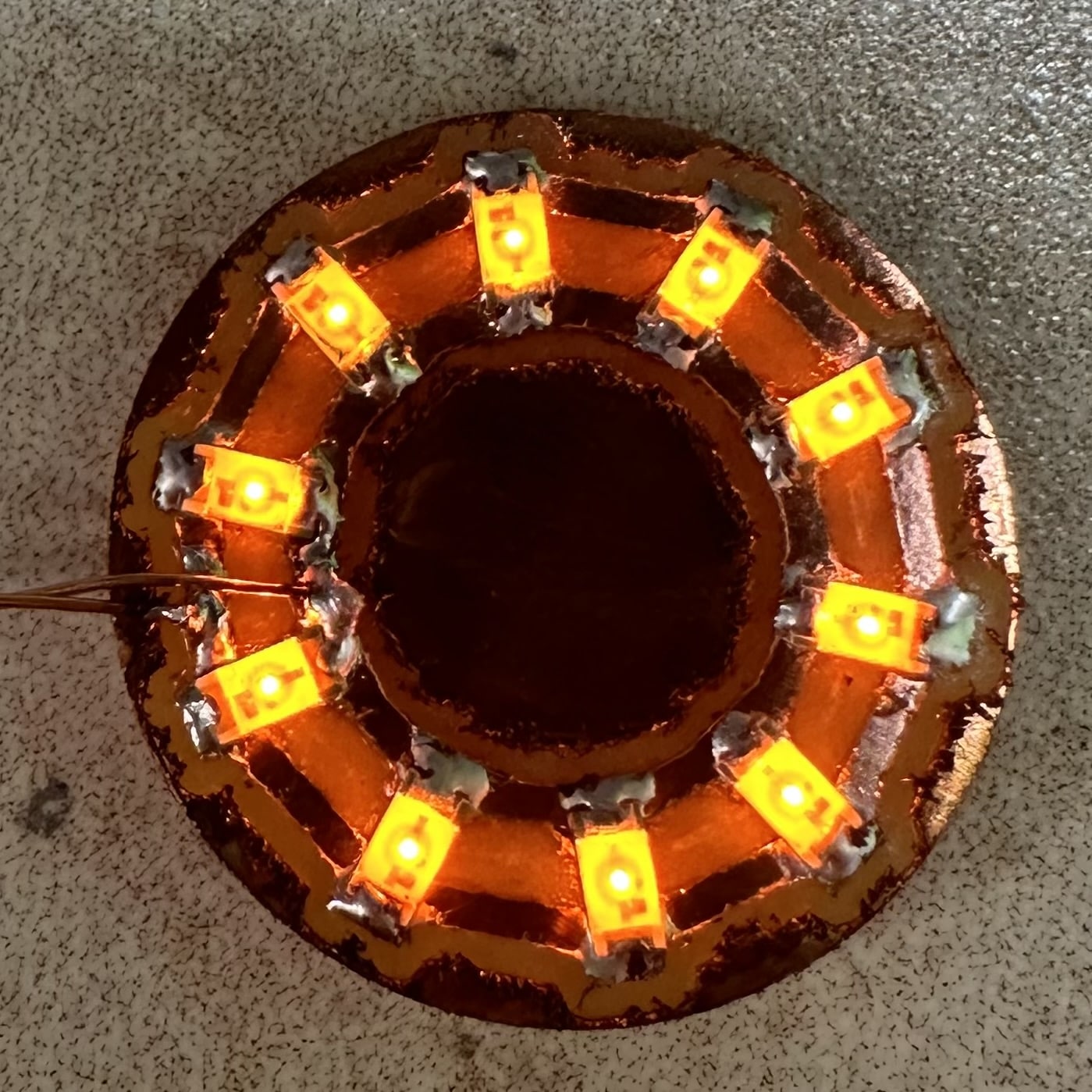
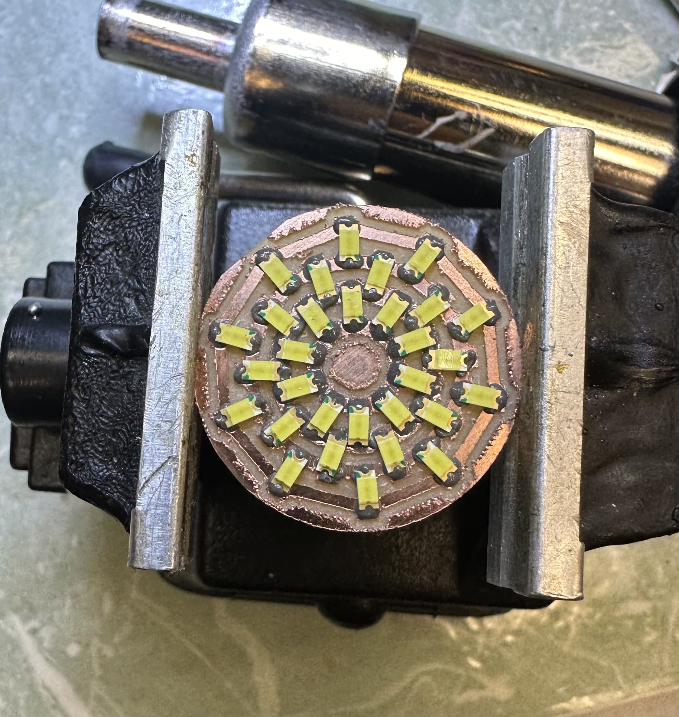
I even tried some more advanced circular designs
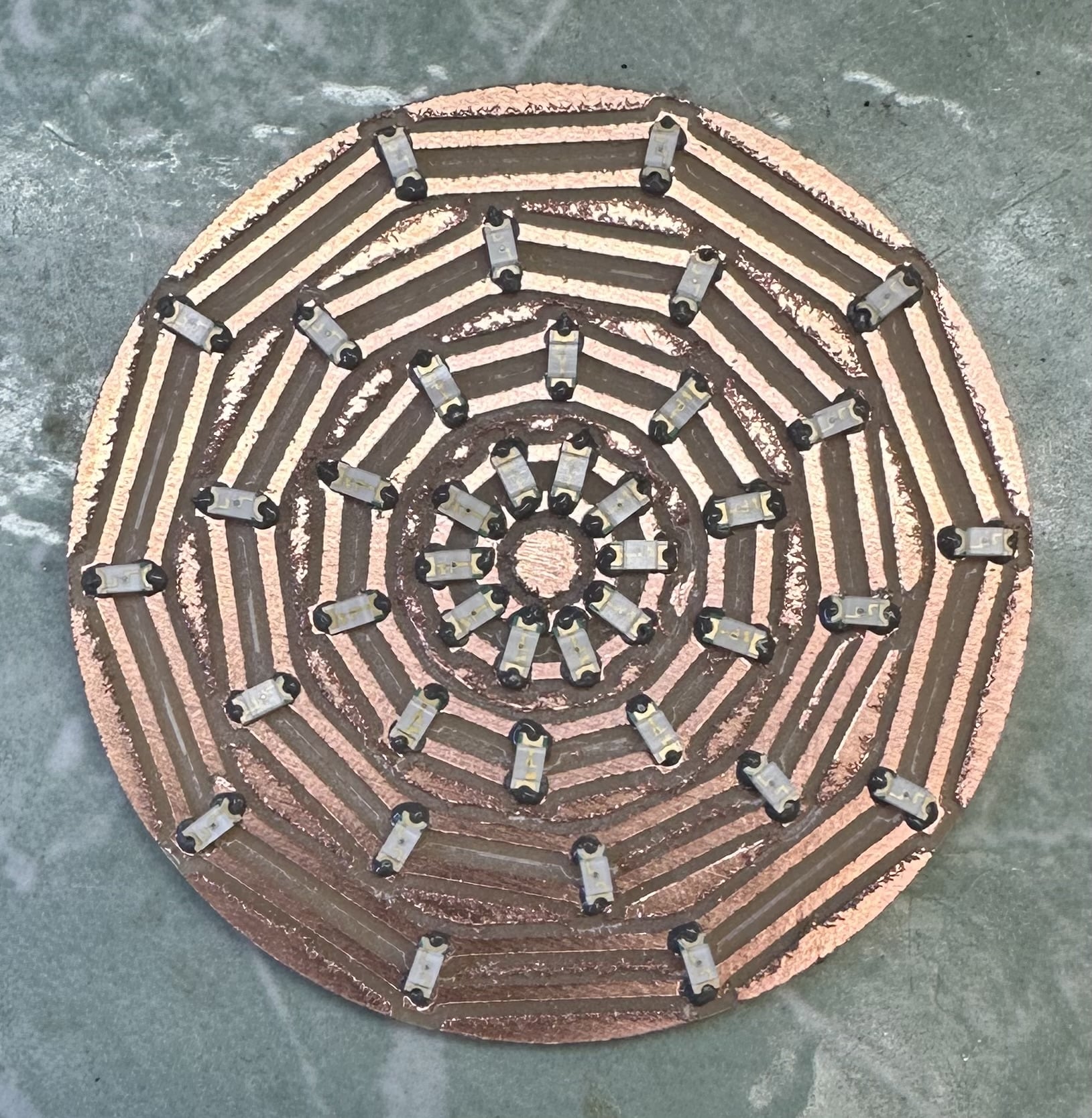
All these circular designs inspired me to make a hand held game with a circular ring of LEDs. I decided to recreate the classic arcade game where you have to time the press of a button when some LED lights line up. Using my circular LED program from before and my knowledge of the ATtiny3228 gained in week 3, I designed this PCB.
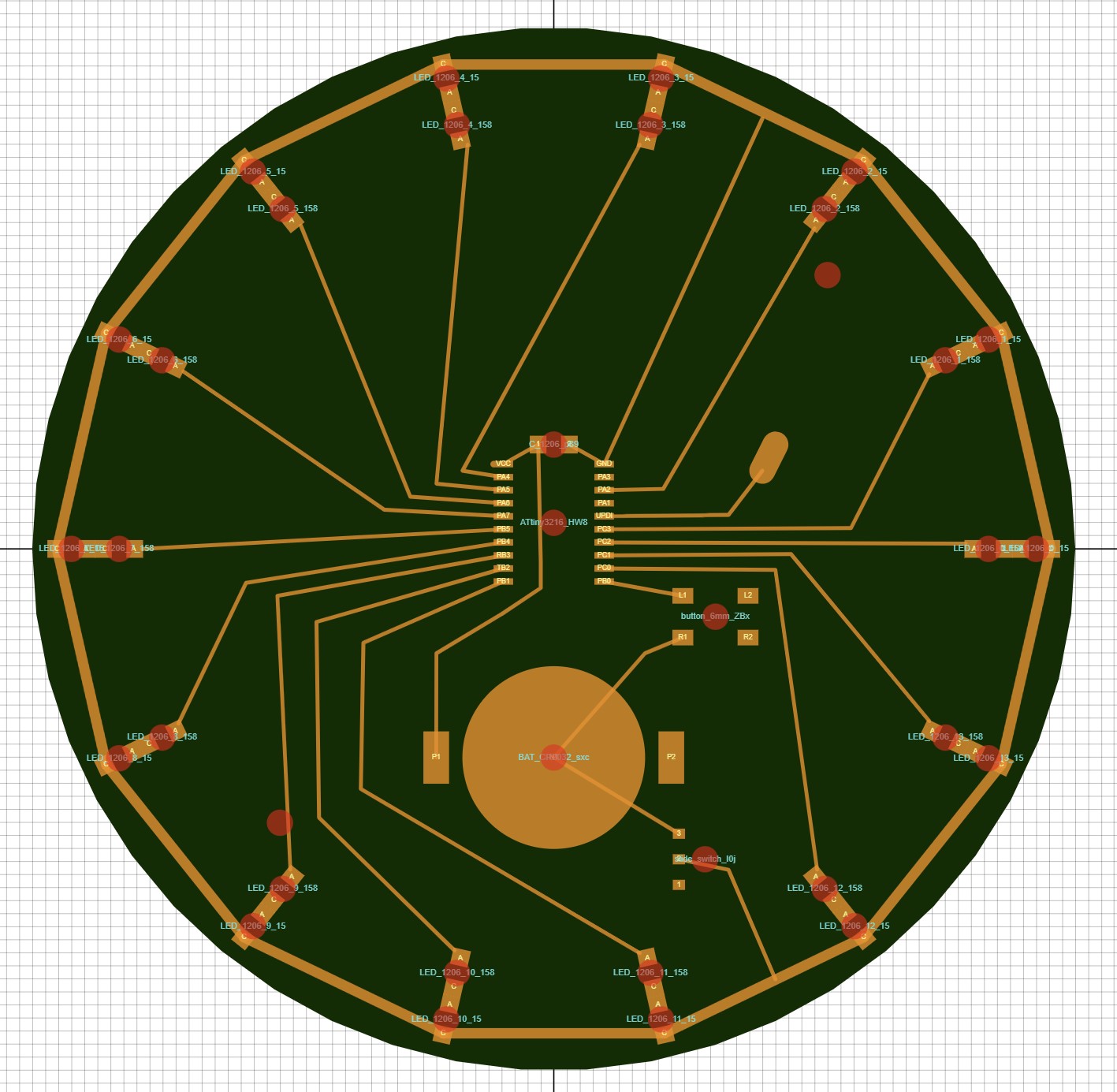
The idea is that there will be a stationary LED and moving led. You need to press the button when the moving LED lines up with the stationary LED and the moving LED gets progressively faster. You can check out the SVG PCB code here. Next week I will mill this board out and program it.