Week 8: How to make a modular PCB - Wed, Oct 30, 2024
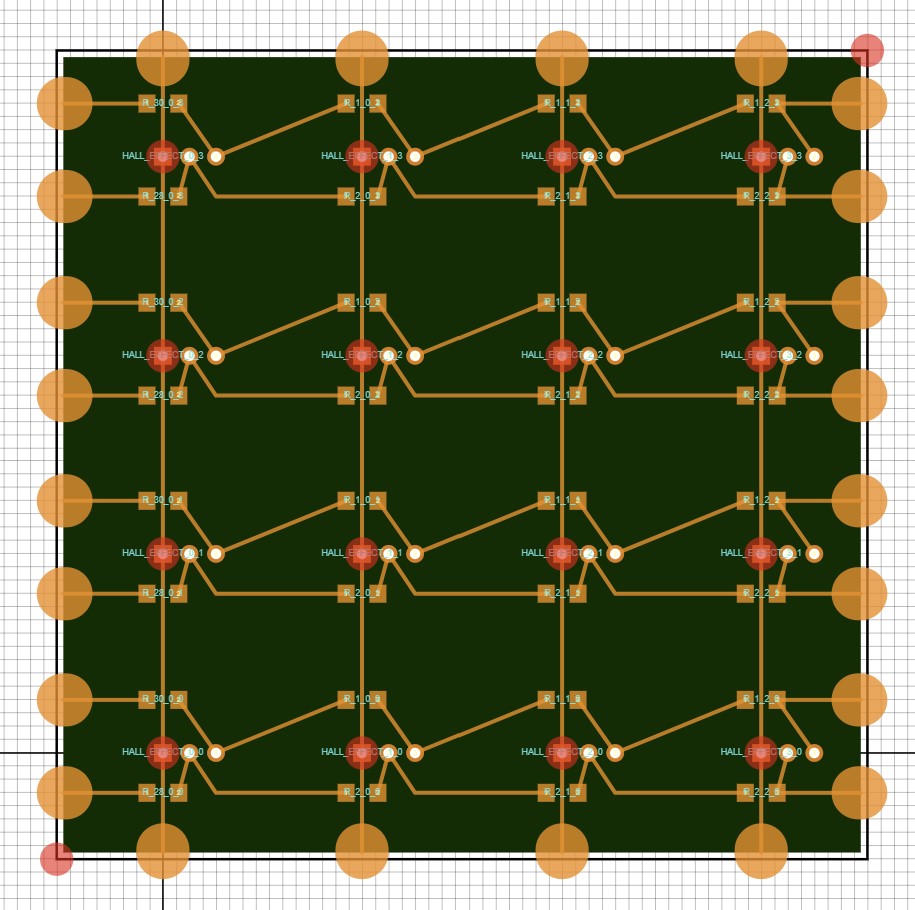
This week our assigmet was to read inputs from a sensor. This was the perfect time to continue working on my interactive game of 15 puzzle. For this I need a gird of 64 hall effect sensor to read the magnetic data off the back of each piece. The main challange will be how I actually make a large PCB in house for all these hall effect sensors, but as I promised in week 3, I will make this board in house goddamnit!
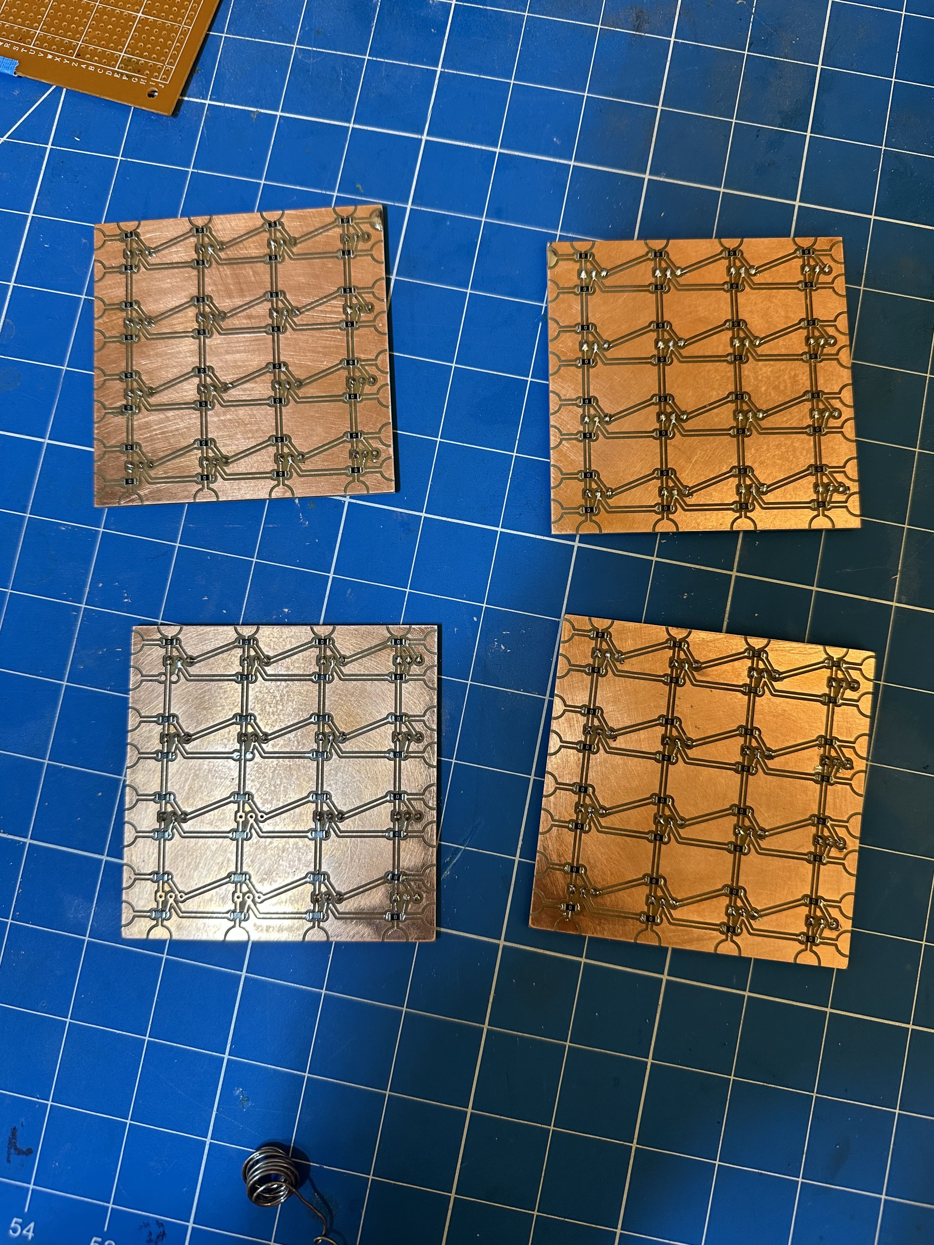
I did not have success using the rolland machine last time I tried to make this board, so this time I opted to make a modular design that I could make on the othermill. This approach likely took more time than just trying to make one large board, but this approach to modular sensor arrays could be very powerful in the future!
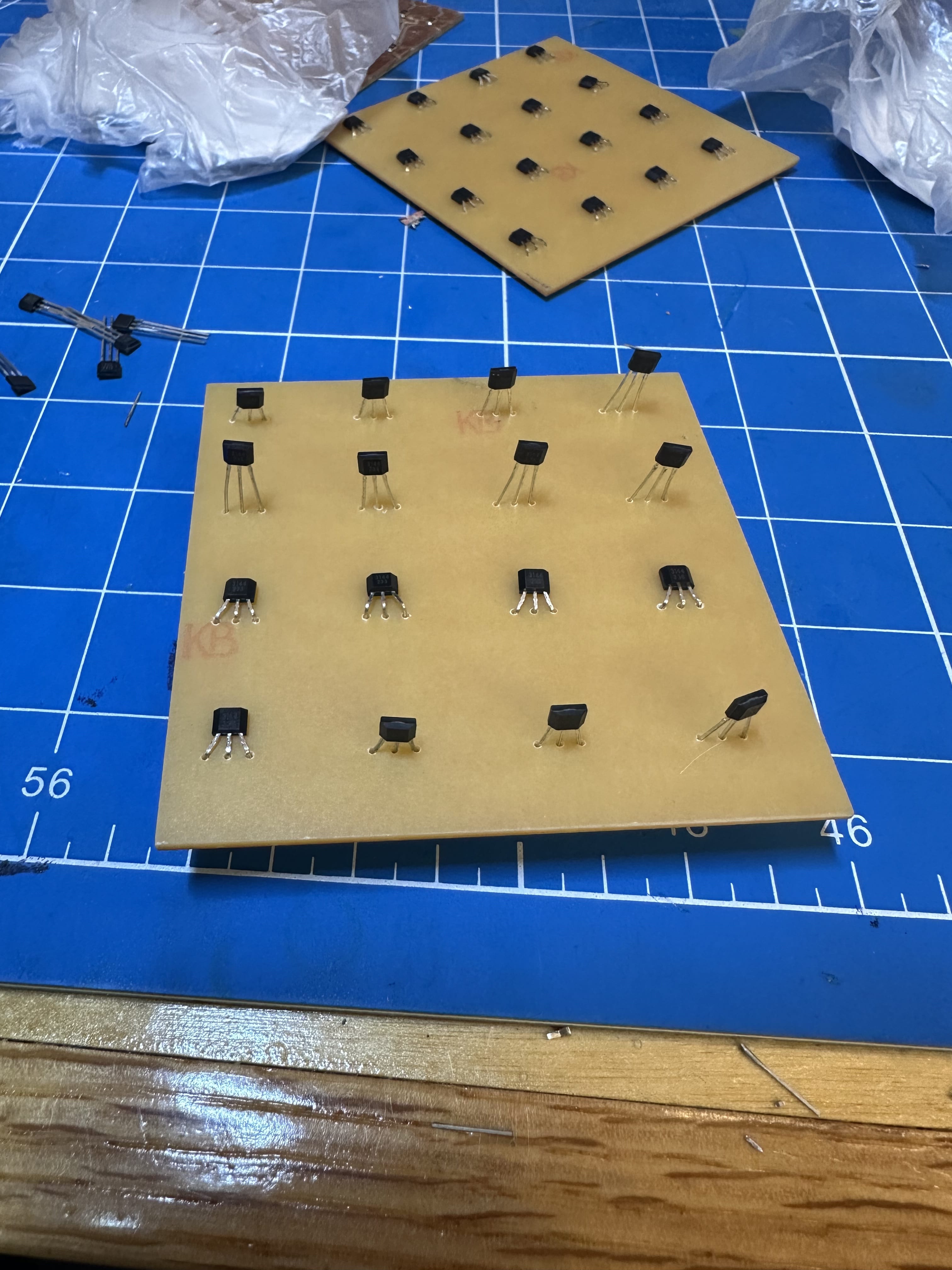
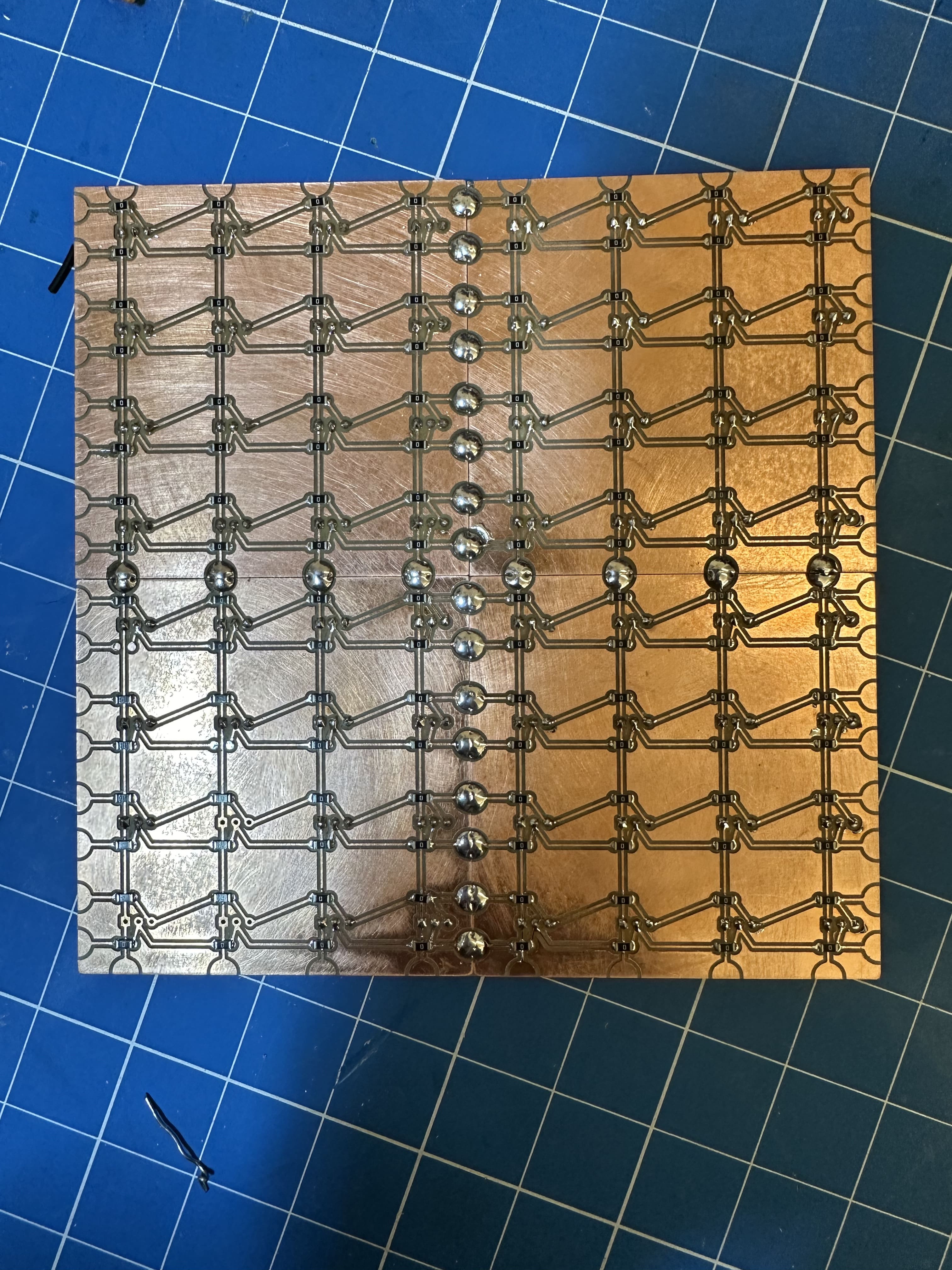
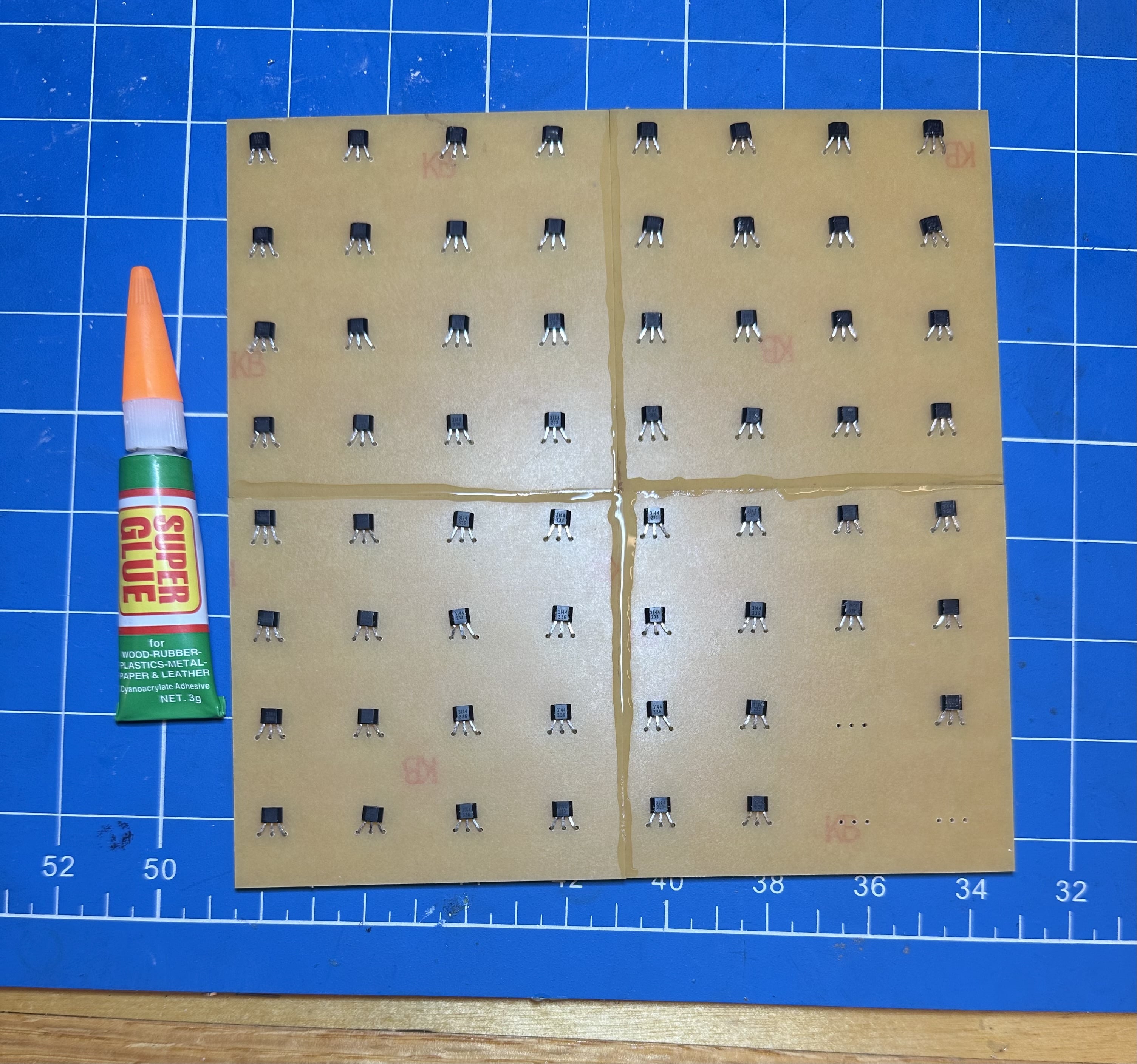
I continued designing the slider puzzle in onshape which you can check out here. I am very concerned about manufacturing this design, so I divided it up into multiple pieces that are held together by 4 M2 screws. Eventually this unit that I designed here will go on a larger and more aesthetically pleasing case that will house all the other electronics as well.
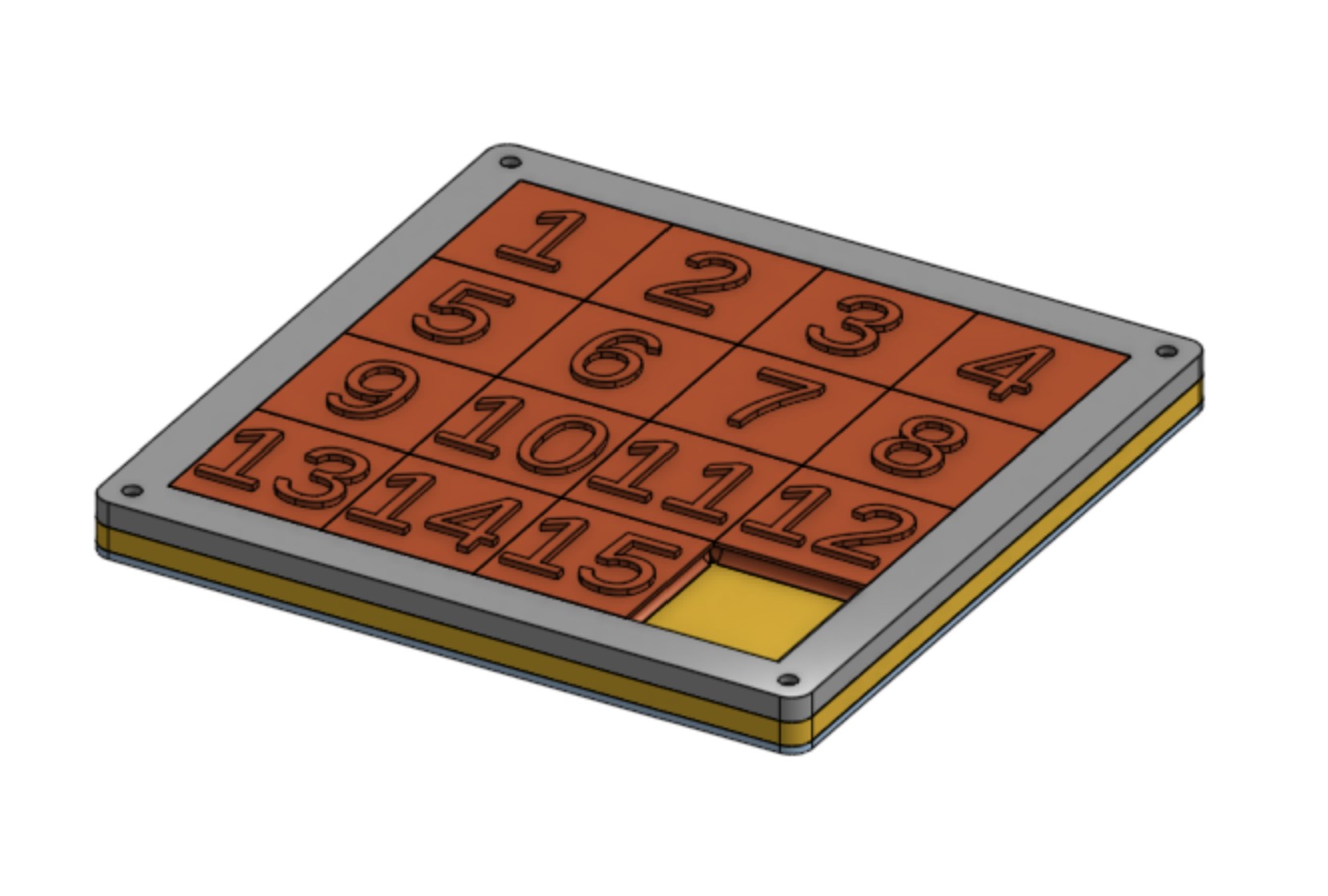
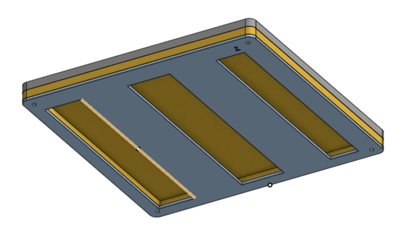
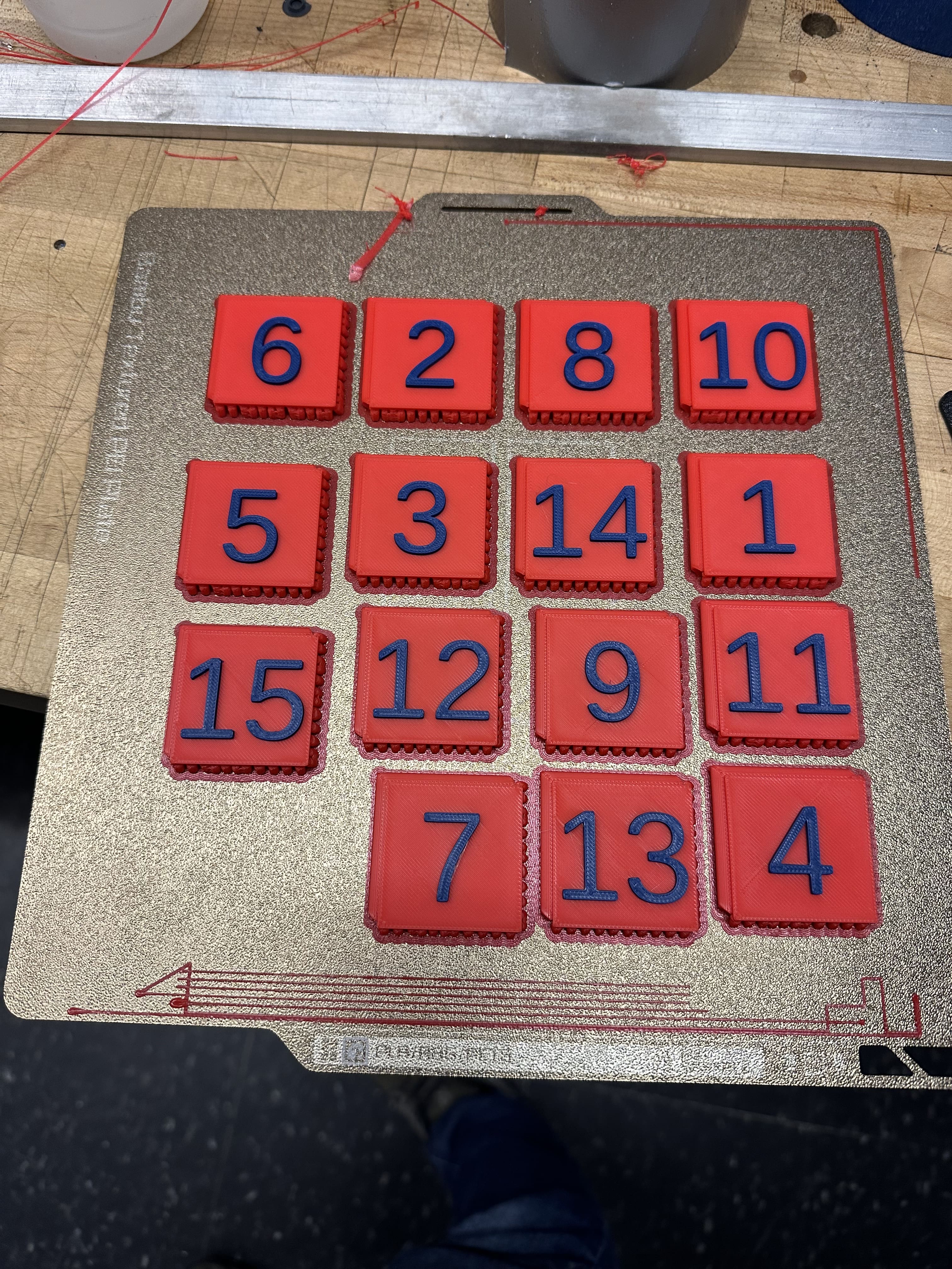
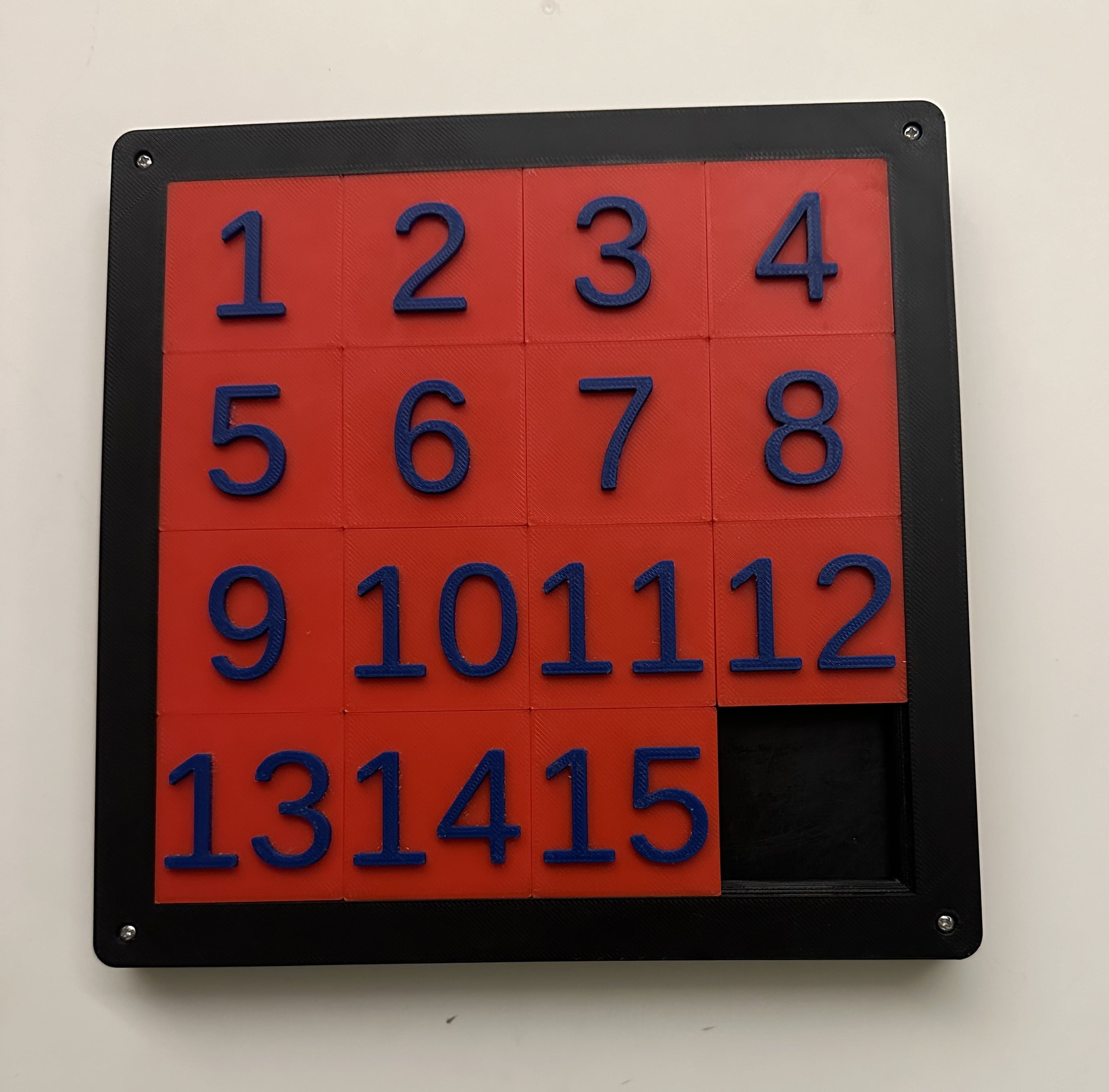
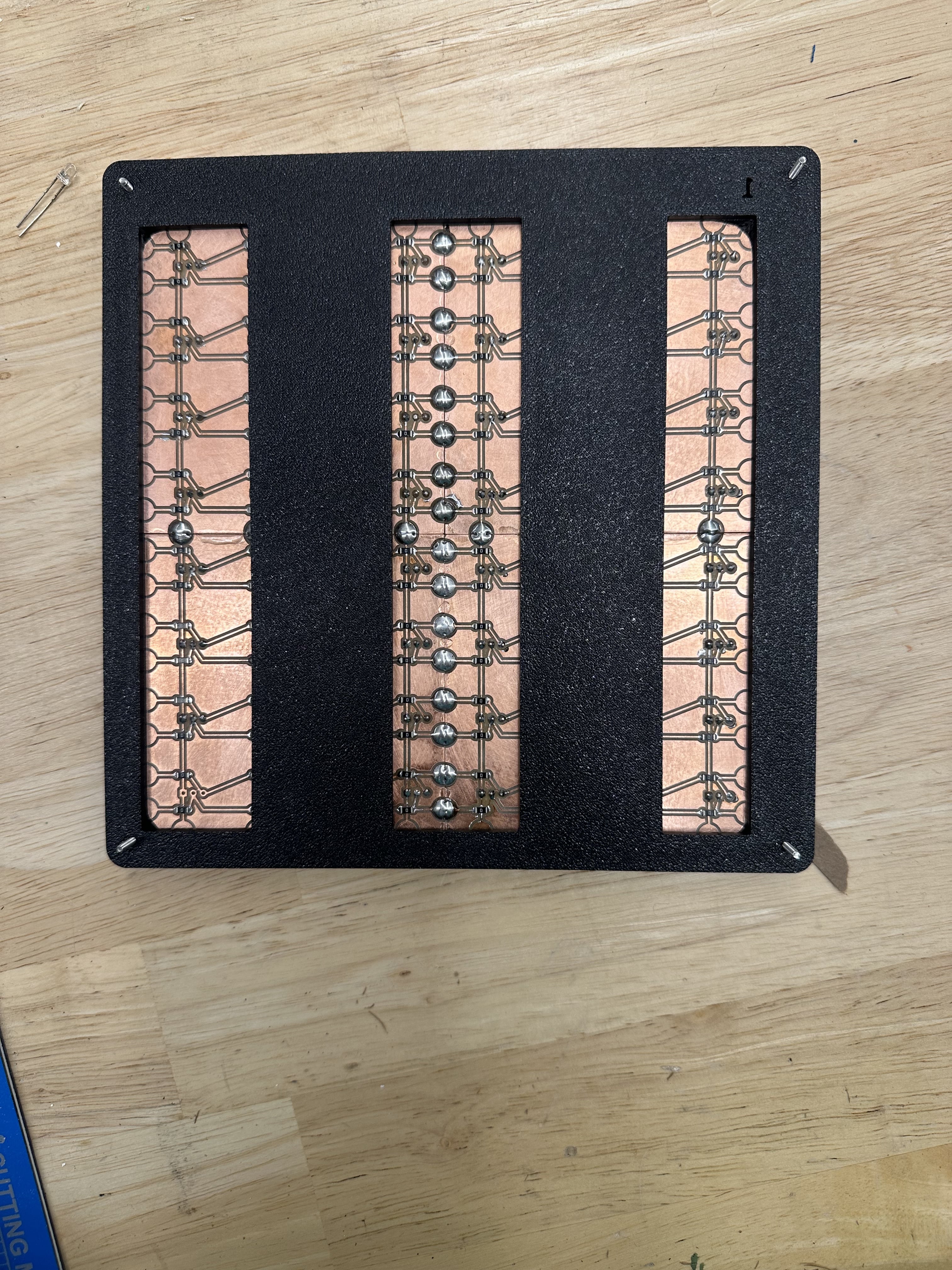
The hall effect sensor grid fit perfectly in the design and I am very excited to continue working on this project!
The local math major/quant approves of the design so far:
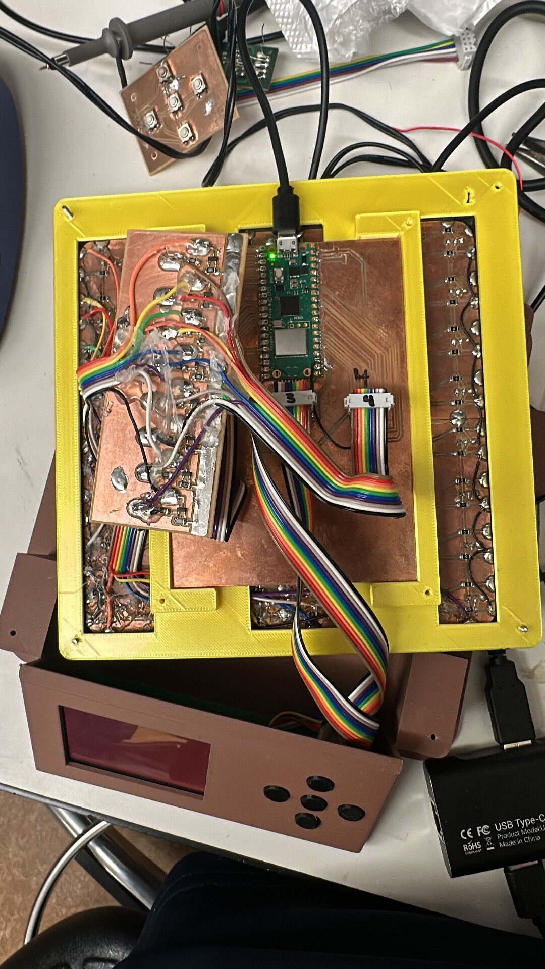
Later in the semester I was able to multiplex the inputs from this grid of hall effect sensors. I used some p-channel MOSFETS to high side switch the rows of hall effect sensors on and off.
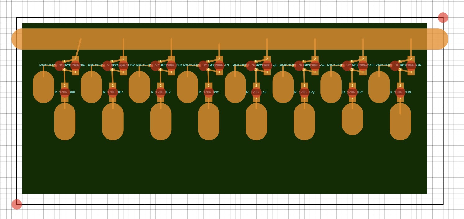
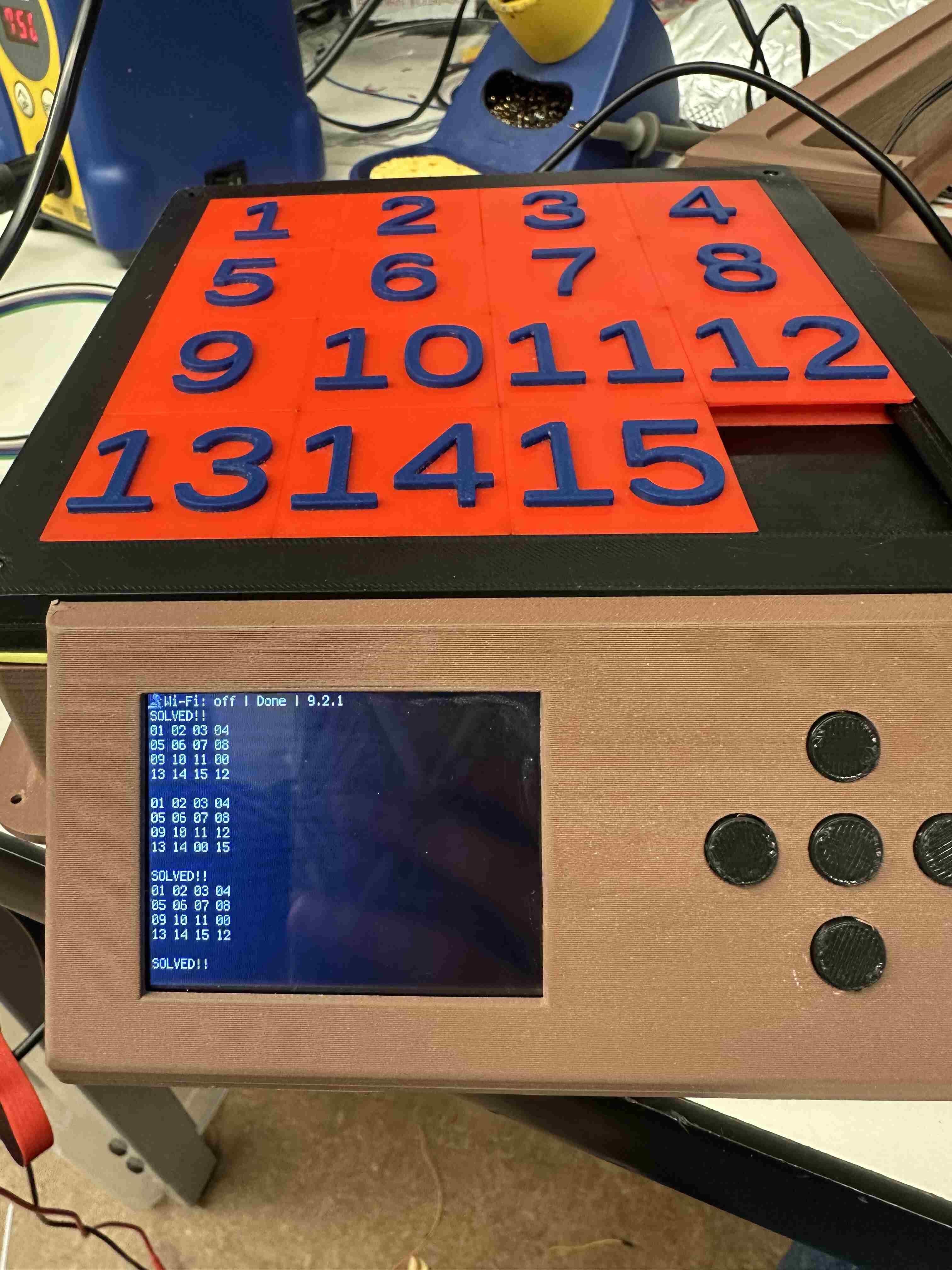
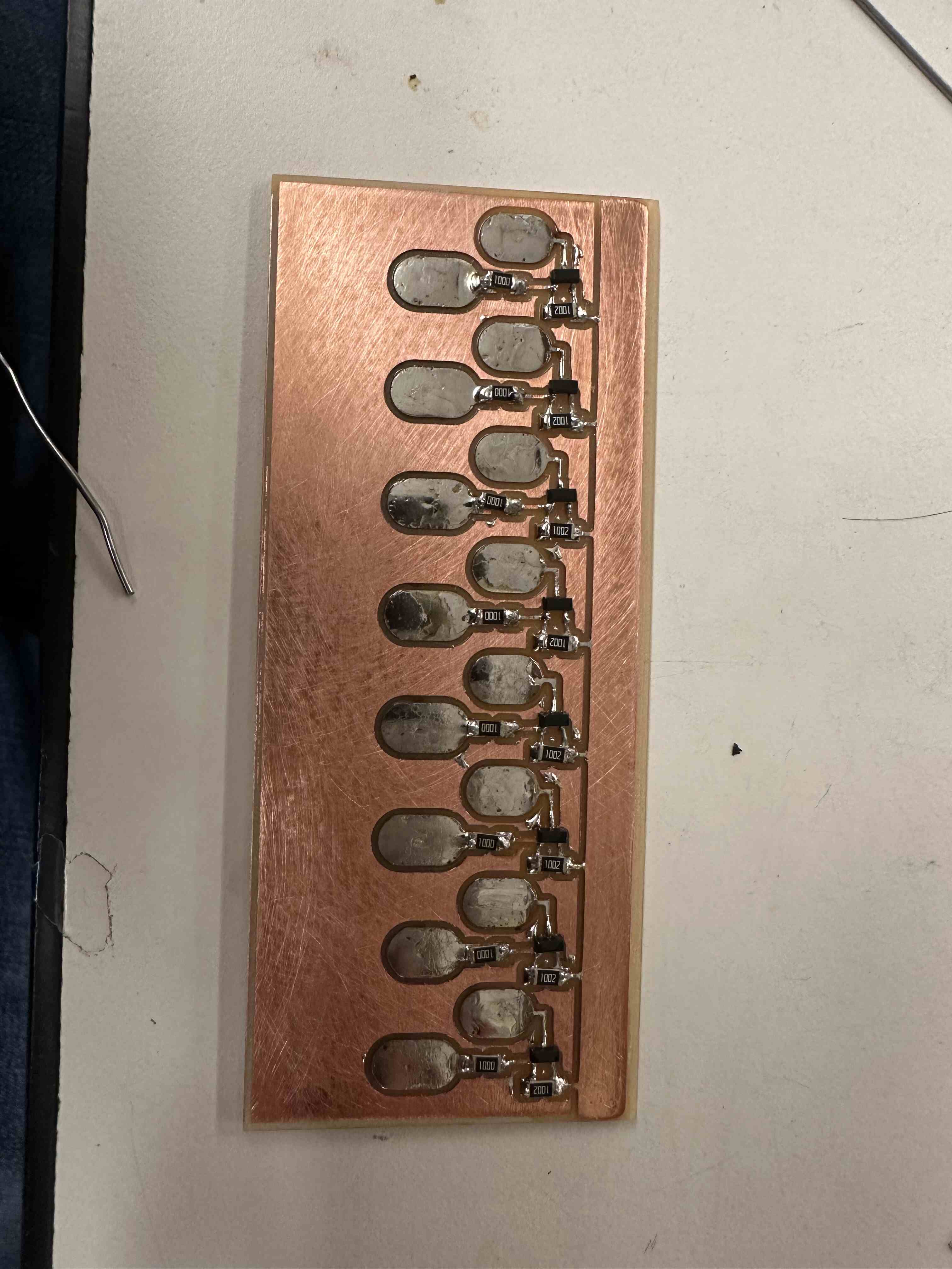 I read the 8 output columns with a raspberry Pi Pico. My main challenge was making sure that all my wire connections were solid and that I had no shorts. After a day of debugging my connections and a liberal amount of hot glue, everything ended up working!
