I made an ergonomic joystick-based controller/keyboard for my visuals.
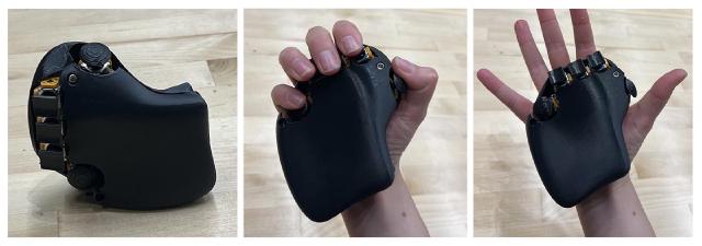
I do livecoded visuals, and usually use a MIDI controller. I also tend to work on cramped seats on busses and planes, and that is hard to do with a full keyboard and trackpad.

I called it BAT, because it was like a flying mouse. I guess it could be a recursive acrynom like BAT is analog typer or something.
Final video 🔗
What does it do? 🔗
It has five 3d joysticks, (give x and y analog data as well as a button press).
The shape of the case and the placement of the boards in the case is ergonomic based on a mold of my hand (folks at the demo complemented its feel, so I guess my hand shape is somewhat universal.)
Some things it’s about to do.
-
It also has a Adafruit ICM20948 in it that measures the data needed for yaw, pitch, roll (I got the data to my computer, but didn’t pull it into OSC for the demo.)
-
It also as I2C attached to a TRRS jack, so I could wire it to a second controller (haven’t tested that, and haven’t built the second controller yet.)
-
It’s also ESP32, so it could be made wireless.
Who’s done what beforehand? 🔗
Ergonomic mice and keyboards exist.
Nikhil told me about Chorded keyboard, and if I do successfully make it a keyboard, it’ll be “keyer” since it doesn’t have a board.
Game and VR controllers were also useful inspiration for ergonomics and toggle sizes and such.
People have created ergonomic mice based on a 3dscan of playdough, like this one.
There were two other hand/glove controllers, including Nina, who was in my section and I learned a lot from.
What sources did you use? 🔗
TAs <3
attiny1624 datasheet, seeed xiao docs, adafruit
chatgpt
What did you design? 🔗
I designed the 4 PCBs and the body, including some little places for all the pieces.
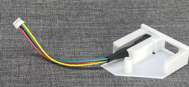
What materials and components were used? Where did they come from? How much did they cost? 🔗
For one board:
- ESP32C3 (I brought my own, since I felt like I’d used a lot during the semester) $4.99
- 5x 3d joysticks (from Marcello, I think it’s these, $2.65 x 5
- adafruit ICM-20948 ($7.32)
- 1 150-ATTINY1624-SSFR ($0.76)
- 3 2x2 male vertical header (CONN HEADER SMD 4POS 2.54MM), $0.32 x 3
- 2 3x2 male vertical header (maybe secret ones?)
- 1 1x6 female (6 Position Receptacle Connector 0.100 (2.54mm) Surface Mount, Right Angle Gold) $0.78
- 2 1x2 female (2 Position Receptacle Connector 0.100 (2.54mm) Surface Mount, Right Angle Gold) $0.43 x 2
- 2 2x2 IDC (CONN RCPT 4POS IDC 28-30AWG GOLD) 0.61 x 2
- 2 2x3 IDC (??)
- TRRS headphone jack (10 of them for a few dollars on Amazon)
- (also found JST connectors, two 5 wire for the fingers. and a 2x1 screw terminal, and a bunch of jumper cables I had.)
- 3d printing (from my own $20 filament)
What parts and systems were made? 🔗
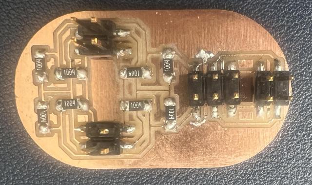
joysticks are wired to the “ADC” board, which communicates via serial to the “Home” board, which currently communicates also via serial to my computer.
The casing was designed (based on a 3d scan, and to position PCBs at the right angles) and 3d printed.
The keycaps were 3d printed.
What tools and processes were used? 🔗
- Fusion 360 for CAD
- Polycam to 3d scan a mold to base the CAD off of
- 3d printing
- PCB Design, electronics
- code (in the course of the final project, I used MicroPython, Arduino-style C++, Rust, and even hexdump’d a file at one point, but I ended up using Arduino-style C++)
and then some (maybe a stretch) processes used that didn’t make it into the final design
- vinyl cutting (for a start of a capacitive touch component that I didn’t quite get to)
- a design for a mold for the toggles (the positive one to use for the negative silicone, to make the positive toggles)
What questions were answered? 🔗
- do joysticks work for a keyboard? they actually feel pretty good! I’m not sure if you get the full usage of all of them (e.g. they don’t move left-right as good as I might need to replicate the corresponding keyboard movement. It’s interesting to think about how “fingers interacting with a separate object they can float around from” vs “fingers interacting with an object they are holding”. ).
- can 3d printing make a quick cheap joystick? maybe but it’s beyond my skills at the moment!
- can 3d scan translate to ergonomics: for the most part, yes! though physical iteration was very useful, especially on the edges of the hand (you can feel it if it ends abruptly).
What worked? What didn’t? 🔗
- custom 3d printed joysticks (idea was to put a magnet in them and use hall effect). it was hard to design them to not sound like fingernail clippings.

Things that I just didn’t get to work
-
having the ergonomic form, did not make it easy to make a cover for it. It’s a little disappointing how that came out, given the amount of effort that went into the part that your hand grips.
-
I didn’t get the capacitive touch part to work, and ran out of time to debug it.
How was it evaluated? 🔗
I had to scale back a lot, but I basically wanted it to work enough to control some visuals. I think I’ll be able to get other things working pretty quickly now (positioning! buttons!)
I was able to send the serial to control the visual software I’ve been building (written in Rust) for the demo.
What are the implications? 🔗
This controller could be a really interesting interface to bring to livecoding, by mixing both ways to create text and to adjust values. (and beyond the joystick, like putting capacitive touch, the fancy accelerometer, encoder wheels…, etc)
the making of… 🔗
Fabrication 🔗
Design 🔗
I wanted this to be ergonomic, and we had learned some things that would help here: 3d scanning.
I started by molding clay into the rough shape of what I wanted. The important shapes were the form against my palm and where exactly to position the tops of the joysticks so my fingers could reach them.
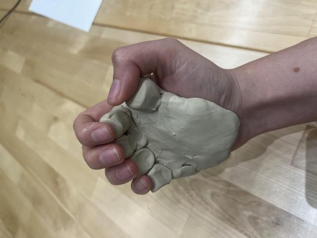
I stuck the clay on a pen so I could film it from many angles. I found a mount in our lab space, and then used polycam on my phone and took a video.

At this point, I could simplify this a little bit: the three fingers, pointer, middle, and ring, are almost in a line, so I could put them all on one board. (spoilers, but after milling the first joystick board, I realized there was no way I could fit a bunch of individual boards for this size of joystick.)
With the free version of Polycam, I could get the points, so I loaded it into blender and tried to clean it up a little bit. I am learning both Blender and Fusion 360 this semester, so it took some fumbling and not being sure which was better for what job.

Then loading it into Fusion360, and fumbling a lot more. Eventually I figured out that STLs get loaded in as a mesh, and there’s an option to turn it into a body. You might need to reduce the number of triangles first though, both to smooth out some useless noise and so that it will work.
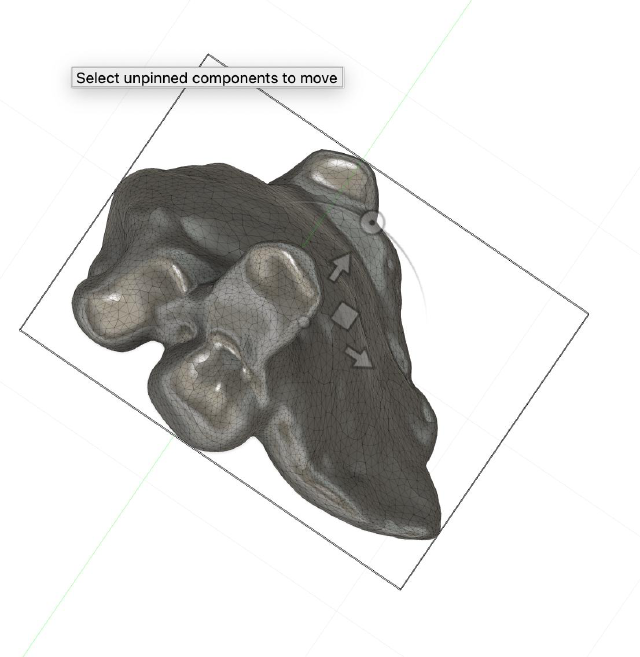
Creating the body itself, I started trying to use a mixture of Forms and extrusions and t-splines, and it was a bit of a mess. I thought it would be better to print it flat, so I put it joystick side facing down and created cillanders to work as joysticks to help me position them.

After I got the joysticks in a good location (v1.x), I had made the first version of the boards and was starting to figure out ways to carve out spots for them to go in v2.x. I also realized that things were going to get really tight, and that maybe having the hand in a slightly more open position would both feel ergonomic and give me more space to cram electronics. Then I learned more about creating Forms in fusion, and created a much smoother
Figuring out the right angle to print is pretty magical. While I starterd with it face down, and super stable, that meant the palm was parallel to the lines, giving really thick lines. Even using the very large spacing of .28, but just tilting the print will give you much better prints.
Here’s an example of a print I did after a few days and had forgotten the magic angle to print it.
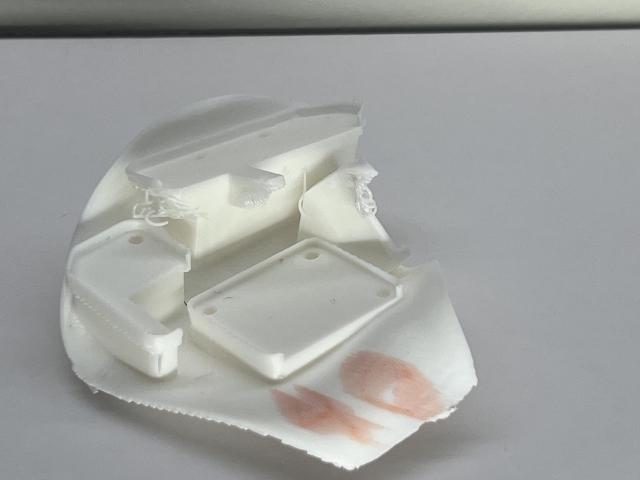
Just tilting it a bit more so there are fewer overhangs (I also thickened the platforms a bit and added chamfers. Youtube told me to go for chamfers and not fillets in 3d printing, since fillets still have vertical.)
Here’s an example of a print. I’d put organic supports on the two blue areas on the palm, and a little in between so it wouldn’t fall over. I would leave the one blue area inside, since that angle didn’t matter much. The angle also made for a pretty good finish on the palm, considering it was the 0.28 draft version. It’s pretty incredible how complicated of a shape coudl be printed with so few overhangs just by tilting it and adding a few supports.

My fusion history had become a mess, so I started over for v4.x with what I knew, and now that I had a set layout for the boards. I created a single form, which looked quite nice. Then I imported SVGs of the boards (including the screw holes and edges but excluding everything else.) I needed to remember which way the boards would face (the joysticks are flipped over). It helped to create some roughly accurate boxes on them to show where thigns stick out, like the joysticks and the pins (but spoilers, wires along with their dupont and IDC connections, take up a bunch of space too, so I needed to do a lot of trial and error in any case.). It was especially critical to maek the joystick tips match up with where my fingers would go, since that was one of the measurements i had created ~5 forms already to refine.
I created little dishes for each of the boards, by offsetting the curve by 0.5mm and 1.5mm. The 0.5 becomes part of the platform to have some wiggle room. the 0.5 to 1.5 is extruded up by 2.5 to give the dish lip. Then I carve down the drill holes. If I’m a bit more than 3.0, it’ll be more of a mechanical stability thing. If I’m a little tighter, the screws will actually bite into the 3d print. This created lovely little
Also, for things that might be screwed and unscrewed a lot (I did it for the part that connects the face plate), you can also put a little slot to drop a nut into (I made it a bit more than 6.0mm across. you want to be able to easily insert the nut, but that it doesn’t twist as you screw into it.)
The joystick boards have stuff going on on both the top and bottom, so I needed to carve out sections of their platforms for that.
I was tired of the weird M2 screws, so I redesigned all of my boards for M3 boards. I used the 5 joysticks allocated for the left hand, and figured I could either remove them from the old boards, or just created the left hand with the few M2 screws I had. (spoilers, I ran out of time to create the left hand, surprise.)
I should have bumped the version here, but I was in the final stretch, so I kept updating v4.x. The new boards also used new types of connectors instead of dupont, so I needed to iterate a bit to get them to fit.
The home board had two I2c slots, one for the IMU and one for the 3.5mm TRRS cable to wire it to the other hand. While waiting for a new palm to print, I designed a tiny lttle case for it, which turned out really nice to iterate on before slotting it into the full design. I could quickly iterate (15 minutes) on the box.


While maybe I could have used the “design a simple box shape holding the boards and then place it in the ergonomic” for the palm+joystick design, I actually think I wouldn’t have saved much time. It usually took 1hour to print (though the final version took 2 hours), and the amount I learned about integration errors in each iteration was very useful: a hole might have one tolerance when printed in a little test block, and a totally different one when printed sideways as part of the full design.
Now I was really in the final stretch and I needed to design a cover. I planned to put the “home” board on the cover, but… after an entire day of modeling and printing, I realized IDC connections are just way too tall, but I went to sleep realizing I could slip it in below the ADC board. I woke up and designed that, and, afraid that I’d run out of white filament and hoping it was the last iteration so I wouldn’t need to mark it up anyway, and it was beautiful.
Form editing by the end 🔗
By the end, I had a good process for creating the form. Create a plane (not a cube) over the flatter parts of yopur shape. change to the move tool, and press Alt and drag, which will create a new square.
The tips are to keep all shapes to have 4 sides. There’s tools like welding, bridging to combine things together, and then subdivision to split it and such. Because my shapes were basically wiggly cups, this was enoguh for me, but there’s also tips about where to put the lines.
Then after you have the surface, leave the form and thicken it to be 1.5mm or so.
I started to figure out how forms worked and started getting smoother
-
needed to check.. connections fit, toggles don’t bump into each other, ergonomics…
-
can try to do fits and such… but depends on what angle its printing at, so trial and error, minimziing changes, might be the best bet
Quicktips 🔗
3d printing 🔗
There are a few things to know here:
-
the angle you print at doesn’t need to be hte default or flat on the ground. actually, getting a lot of it on the bed can make it slow and less strong, so holding it up at an angle could be better. kind of odd, but a box with half a lid on it, held on the corner, could be without many supports at all, because 3d printing can happen at angles pretty well! but still need supports.
-
I usually paint on the supports, so i don’t have quite so many. i use organic.
CAD 🔗
- to make the things that hold the PCBs, i tended to split body, then remove. but that does lead to it getting angry.
- go back in hstiroy and step through until things break.
- I made components for the joysticks for example. one convenient thing is that you don’t accidentally modify it. you can also have multiple copies, and they’ll all update. which was useful when i updated a board.
Keycaps 🔗
I was doubting the joystick approach until I printed out keycaps.
I started with an OpenSCAD library I found here: https://www.thingiverse.com/thing:2783650 . This allowed for a ton of customization (with slants and angles depending on the which key on the keyboard you’re printing). I started with a default one, but with no connector (e.g. not cherry mx)
I loaded it into Fusion… and fumbled a bit figuring out how to convert the mesh into a parametric object I could start editing.
I filled in they keycap, and then cut out a shape that was the (nominal) of the joystick: a circle 4mm in diameter, with the tops and bottom cut off so it would be 3mm. (I ended up needing to adjust this depending on what angle I was printing the keycap, and for the different versions, so watch out!)
They keycap was great and funny enough. It does look more like a weird keyboard with mechanical keyboard caps on it.
But unfortunately, they also woudl bump into each other. I tried another design that kept the top few mm of the keycap, but had a thin thing to
The thumb toggle is a portion of a circle with little circular notches removed for grips, revolved.
Molding 🔗
I made a mold for a Silicon mold to try molding them. I was discouraged imaginging of all of the bubbles that would get into the tiny details of the shape, and so I put it lower on the priority list and didn’t end up trying it before the final.
Electronics 🔗
started testing the final board with a multimeter. realized flipping the IDC connectors didn’t actually rotate the pins, so VCC was on the wrong side. I just twisted the ground and vcc wires and attached a new connector.
Electronics Production 🔗
Design 🔗
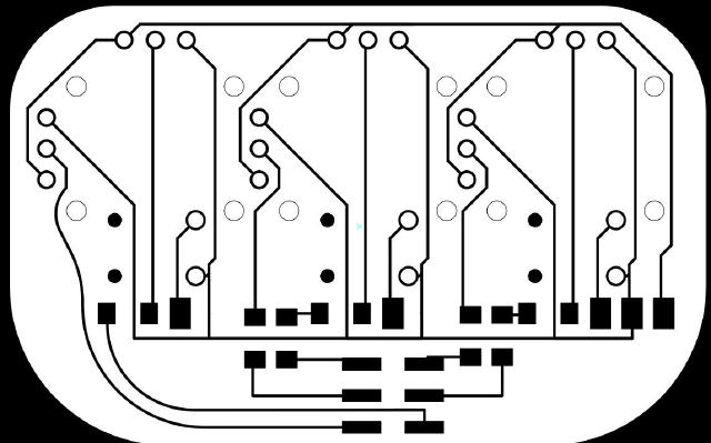
at a minimum, there 4 PCB designs.
- the 3 finger board
- the 1 finger board
- the analog-to-digital-converter board (e.g. attiny)
- the esp32 board.
The cool thing is that this is really modular. First of all, by breaking up the fingers ofthe board, you can adjust it to match where your fingers naturally want to be.
It also means that the right and left hand uses the same set of boards. (though to be honest, i didn’t finish modeling the left hand. but i think it should all fit.)
Home board 🔗
This one holds the ESP32, and has I2C ports (which, in the right hand, I use for the ICM20948, and the jack for another board. but either could be replaced with other I2C devices in the future), and the Serial port to connect to the ADC board.
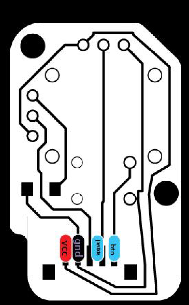
ADC 🔗
This one translates 8 analog pins into serial output. I started with I2C, but realized i couldn’t use the default pins because those were my valuable analog pins.
3 finger board 🔗
a row of 3 fingers for the ring, middle, and pointer finger.
one finger board 🔗
just one finger, for the pinky and thumb.
How to Electronics Production in general 🔗
I liked having a lot of control over this, so I usually used a combination of KiCAD and a vector editing software (I used illustrator, but InkScape is another option. I also generate my own SVGs a lot in my software, but I didn’t get around to using it here.. But because my workflow was a bit agnostic, I can drop it in.)
Using a relly general purpose tool meant that i could make weirder boards.
Footprint: the places the things attach to. These shapes should be kept together or else your piece won’t fit! (Sometimes you can go in and adjust these a bit.)
Traces: the wires. You can change these a lot, make them curved, etc. Keep them around 2mm at a minimum (or 3mm if your drill bit is possibly broken), and maybe make power and ground a bit thicker.
board edges: these include both the outline of the board. curve your corners so its less sharp, put 3mm holes to fit M3 screws (or if you have access to 2mm screws/2.7mm). and isolate them.
throughholes: “THT”, “through hole technology”. We use them a little less, because they’re usually for breadboards. But on PCBs they’re a little stronger too. and some pieces just have to use it, e.g. the joysticks. but on the other hand, that mechanical movement sometimes traces get lifted.
surface mount: SMT (surface mount technology). these get nice and small. They can get even smaller.
Ways to join it:
-
use lots of flux. there’s some in the wire, but your life gets a lot easier if you take a dispensing needle of flux and dab it on there. the smoke rises, the solder hugs your pins and copper. It’s especially useful for attaching wires on components (wires, ), that can get all oxidized
-
hold it down with double sided tape, rotate it so it’s easier to reach.
-
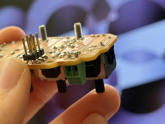
UV resin is like $8 for too much of it, and then $15ish for a UV light. it can help hold down traces that are starting to lift. But! Be careful not to let it seep into your (female THT), so that you bond a useless thing to your board.
Here’s a throughhole component lifting some traces. Since the traces were still connected, I put some UV resin on this to keep it together.
ways to unjoin it:
- for moist things, heat guns, and hold it with tweezers. I had a lot of trouble with the xiaos previously though…
- use tht, solder headers pins onto them so it’s removable…
safety
- don’t forget carbon fan things, make sure the smoke from the flux gets sucked through those instead of your face.
- don’t be dumb and try to move the heat gun box after 7 hours of milling/soldering so that you burn your thumb knuckle. But if you do, and saniderm seems to work great at protecting little burns.
- things that conduct electricity also conduct heat really well. e.g. holding one side of a tiny wire while soldering the other will make it hot. use coated tweezers, or worst case big metal ones.
- take breaks/stretch/get fresh air/etc.
This also means that THT will start to melt the plastic when you’re trying to bond it. flux helps a lot here, since you don’t have to hold the iron to it as long for it to start flowing.
solder joints, you’ll hear it a lot, but basically you need both sides to be heated up so the solder joins to both sides.
Shorts 🔗
I… made PCBs begin to smoke on 3 different occasions, so I have authority to tell you how to avoid that.
Try to wire things up correctly before milling. But you can return to this step if you have to. There are a few things that can go wrong: moving a footprint object over a new wire.
When you get the gcode, double check that too. Sometimes the tool is too big, so the toolpaths end up joining things that shouldn’t be. These are pretty annoying to fix, so it’s nice to catch it early.
After milling the board, it’s a good idea to hold the board up to the light and check for traces incorrectly connected by little bits of copper. You can clean tiny ones up by running a piece of metal over it. This is especially useful for places where components will cover the trace and it’s harder to fix later (I had a short under my attiny, and had to remove it…)
Before plugging it in, take a multimeter, set it to the “make a noise” and hold one pin to the VCC, and tap every other pin you can reach. Open your PCB board diagram, and make sure the only pins that make a noise are supposed to be connected to VCC.
Correcting:
-
Bigger ones (e.g. where the toolpath joined traces to pads it shouldn’t have), can score it with a knife, but this is hard: you have to push pretty hard, and if it slips you can knick a trace you didn’t want to.
-
if on the other hand, you have two things not connected, you can correct it by just attaching a wire. It’s easier to attach the wire to where a component is already attached. I had the most luck when I mechanically joined them (e.g. wrap the wire around the pin) and then try to solder it. It’s difficult attaching 3 things to one spot though. Wire wise, your life will be infinitely easier with single strand silicon coated wire. the PCB coating of other wires will melt, the strands will fray. (you should hold it with tweezers, but you can even hold the silicon with your hand)
when working listen/smell/see smoke, then unplug it asap.
-
the first time, was a 3d joystick I wired incorrectly. I thought my 3d printer was acting up and ran off to check, and then came back and realized it was coming from the joystick. I unplugged it, and worked with other joysticks. I thought it was because it was cheap off of amazon, but now i think it’s because I shorted the button.
-
the second time and third time was because I had accidentally wired a 5k resistor between VCC and ground instead of horizontal pins… I could have noticed that by doing the VCC-to-everything test.
KiCAD 🔗
If a component doesn’t exist, but you have a diagram from a datasheet, you can map it out a new footprint in KiCAD.
The joysticks I used, I didn’t have a footprint for, but I did have this diagram. They shoudl tell you all of the distances. (you edit the footprints, and then assign pin numbers (1, 2, 3…) to each pin). (i ended up doing throughholes in vector-editing anyway)
before wiring things up, it’s good to at least set the constraints to 0.8mm (depending on your drill bit width.) This way your traces will sticky far from them. If you change this later, it’ll get annoying to edit becasue traces will be violating , so you can’t even fix them..
custom footprint 🔗
- create a custom footprint, name numbers
- then edit symbol, symbol properties, set footprint
other tips 🔗
thicknesses, .2 is okay but might fail for long traces with a broken endmill. .3mm is better.
Testing 🔗
After I had all of the boards produced, I tried wiring them all together.

Then I tried putting it in the current palm design I had. (I threw in the programmer so I could make sure I could fit the home board in there.)
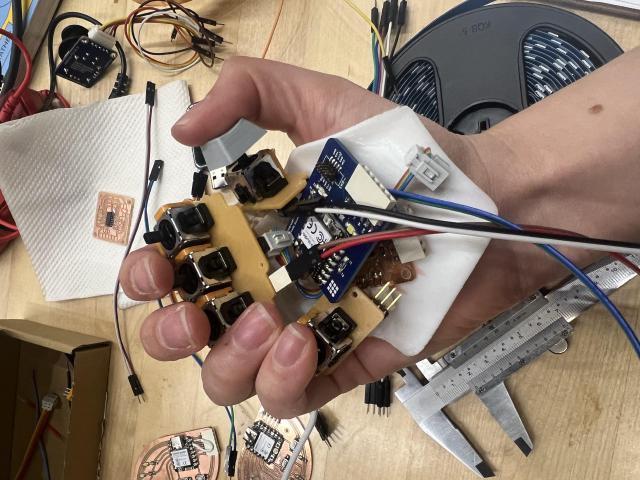
This was okay, but kind of hard to move the joysticks. I wanted to reach this point early so I could see if I needed to abandon joysticks, and I was highly considering it.
Then I printed off a keycap and.. my opinion totally changed, this was great.
Programming 🔗
Quick Links 🔗
Code I used on the ESP32C3 here.
Code I used on the ATtiny1624 here.
Live journaling 🔗
Hmm, it’s starting poorly: i uploaded some i2c scan code anddd, the device doesn’t show up. I check pins, I use the adafruit library, i create Wire with the gpio pins (6 and 7, not the D4 and D5 from the label)
https://files.seeedstudio.com/wiki/XIAO/Seeed-Studio-XIAO-Series-SOM-Datasheet.pdf
but the nice thing about IDC is that you can use the same headers for jumpers, which is great for debugging or if you need a bit more length but you have to remember the order of them. i tried to mark the same wire on each side (and ground in the case of a jst to IDC)
well, after good luck with the Adafruit ICM20948, I wasn’t seeing anything from the ADC, or the buttons.
argh, and updating the code now got an error. I thought it was because i needed to hold down the boot button, which wasn’t very accessible when it’s attached (maybe i coudl get a toothpick in there, but all my things i had were conductiveand i figured i’d need to do it a lot, so I just removed it.)
because chatgpt sometimes gave me the wrong pins, I also looked at https://wiki.seeedstudio.com/XIAO_ESP32C3_Getting_Started/
- i unattached one of the joysticks so i could start testing the pins underneath.
- i, eeek, had swapped the “lone joystick” and “adc rx/tx”, luckily using the gnd/vcc conventions meant that i was still sending gnd/vcc and just using the wrong pins for data, so I didn’t fry anything. I swapped those, and the joystick started to send data on one pin. I was using numbers for the pins, so I switched it to
A0andA1like the Seeed documentation, and started getting joystick data, yay. - none of the buttons were working, but ChatGPT reminded me to use the interal resistor and set
pinMode(D10, INPUT_PULLUP);. With this, 4 out of 5 buttons were working, and the joystick plugged directly into the home board completely worked. - oh no, i tried code that used RX, TX, which left the esp32… unable to work. it would give me A fatal error occurred: `Failed to connect to ESP32-C3: Wrong boot mode detected (0x2)! The chip needs to be in download mode. I eventually got it to work by holding down the boot button while plugging it in (took me a few tries because the board is now awkwardly upsidedown.)
- still no luck. i plugged it into the Arduino nano every that I had gotten working with the ATtiny a few weeks ago.
took a break for sleep.
- copied over the
serialADCcode to the esp, but this time just a little sketch to print things. Hooked that up to the nano every and… it works? so that tells me the nano is working. - well, well i’m here, let me make sure the serial read works on the ESP32. and serial read works beautifully.
- hm, but serial write isn’t working at all. chatgpt says something about the while !(SerialADC) might be causing problems. I guess you need it in some cases, but not universally. I should double check this at some point.
- I get the very basic serial working again, so back to trying to read it.
- resource busy means a serial monitor is open somewhere.
- chatgpt mentions that it might have to do with arduino working on 5V, while the esp works on 3.3V. i’m not sure if that’s causing it, but i don’t want to find out because the Arduino was just introduced to help debug, not meant to be debugged itself.
- so i try a loopback test instead, where you plug the ESP32’s tx into rx. that happily outputs. so i successfully get rx and tx to talk to each other on the esp, so i know the esp can read from those pins okay.
- i upload the analog_read code to the ATTiny again, removing a while loop and adding a delay instead.
- Still nothing. I start using a multimeter. hmm, everything is always 0 from the installed board… i guess, let’s try the other ADC board.
- okay, this one gives a lot of 1s on one line, and then 0s and 1s on the other line if i tap the pins a bit.
- i also tried plugging their rx/tx lines into an led, and the installed board is giving… 0s. (i made sure that VCC/GND hooked up to the board lit up the LED, and then i swapped VCC for the RX/TX). Soo something is up with the installed board.
okay, went into the lab. got the logic analyzer. I want to compare the signal coming out of the (working) attiny to the signal coming out of the esp that’s talking to itself, to check if there’s obvious bit parity or voltage issues.
the code should be running already. first, i use the esp to just power the attiny, and put ground on my ground, and test tx and rx. nothing shows up, so i double check with the LED trick. one is dim and flickering, and the other is bright. but if I try the same pins in the logic analyzer, they’re both high the whole time. I’m still new to the logic analyzer, so I wonder if I have something misconfigured, so I switch to analog and it’s the same. I see now, the digital will clean up the 0s and 1s, where the analog, you get to see those beautiful weird spikes that happen when the pin first turns on.
Quentin stopped by the electronics lab and said that it being high was good, that’s what serial looks like when it’s not talking. And to go back to test something easier.
So I upload some code to have the light turn on and off every 500ms.
It is not. I test all of the pins. The UPDI is high, it sounds like that’s good normal.
I go back to poking pymcuprog. I’m still suspicious of fuses. I figure out how to dump the fuse memory.
./venv/bin/pymcuprog read -t uart -d attiny1624 -m fuses -u /dev/ttyACM0
Connecting to SerialUPDI
Pinging device...
Ping response: 1E942A
Reading...
Memory type: fuses
---------------------------------------------------------
0x001280: 00 00 7E FF FF F6 FF 00 00 xx xx xx xx xx xx xx
---------------------------------------------------------


Done.
I skim through section 7.8 of the datasheet breaks down what each of those bits should be. (ah, reminds me of the networking where I spent time with the bluetooth datasheets). I don’t really follow what each of these are, but I wonder about brown out detection, which will protect if the voltage is too low. E.g. if I’m operating at 3v3 (which is allowed), but it thinks it should be closer to 5V.
7E -> 0111 1110, and the docs say the first 3 MSB are level… so this is 2.95V (not 7 -> 4.3 like i first thought) wait, actually the offset for brown out detection is 0x1, and that’s 00, so.. this is not what I think it is: it’s 0 to mean OSCLOCK, something about the oscillator being accessible, and then most of the 1s are because those bits are unused, and then the last two bits means to run at 20 MHz. I also wonder if that’s acting up, because ChatGPT keeps mentioning the clock on the ATtiny acting up.
I’m losing hope now, feels like everything is rabbit holes. I think about switching out the chip. Maybe using a more lowkey serial to UPDI thing instead of the universal programmer in case there’s something introduced there?
Lingdong had made me a 1624 to show that it could be happily programmed from a Mac without VMs and such. It happily blinked the lights. Hm, could I check the fuses?
0x001280: 00 00 02 FF FF F6 04 00 00 xx xx xx xx xx xx xx
those are.. a bit different. Like 0x2 to 02 (instead of my 7E), and 0x5 is 04 instead of FF.
I fumble a bit, chatgpt tells me to just update the lfuse/hfuse and to look at fuse calculators online, but it seems like those things are all about older ATtiny. I decode the pymcuprog help page’s example of writing the fuses, (I change it to read from address 2, which prints out 7E) with pymcuprog and eventually to get them to match by running:
./venv/bin/pymcuprog write -t uart -d attiny1624 -m fuses --o 2 -l 0x02 -u /dev/ttyACM0
./venv/bin/pymcuprog write -t uart -d attiny1624 -m fuses --o 6 -l 0x04 -u /dev/ttyACM0
well.. that went well. Can I just read the flash from the working device. I am desparate to make the thing blink.
I write the flash memory to a binary file.
./venv/bin/pymcuprog write -t uart -m flash -u /dev/ttyACM0 -d attiny1624 -f out_flash.bin --clk 9600 -v debug
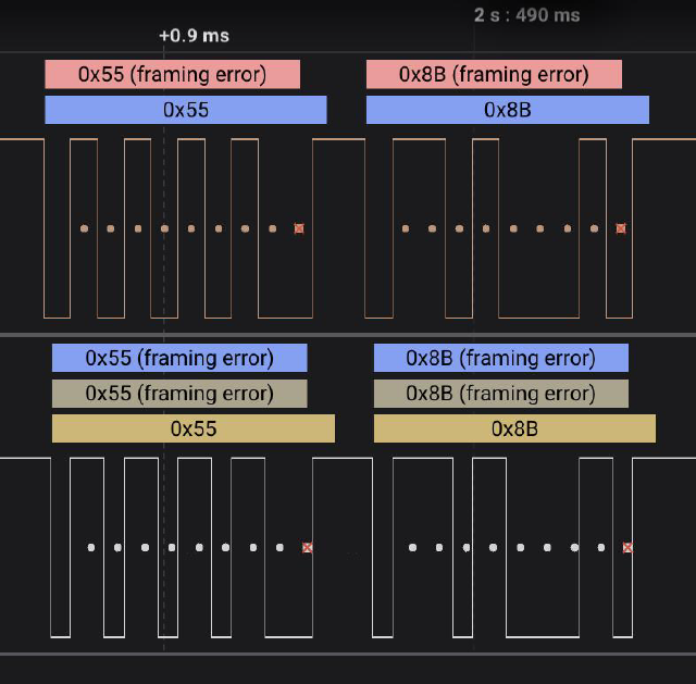
Then I upload it, trying a faster speed. I’m tired of seeing the same thing on the logic analyzer, so I watch the rx/tx when it’s uploading. Yay, bytes.
I select the async serial, but I have to sort out the baud rate and parity. It sounds like baud rate is the reciprocal of the length of the bit, so 1/.00000872 which is just about 115200 like i expected because that’s what i told pymcuprog to use.
I choose the defaults of the rest, but still get a framing error. So I chose an arbitrary parity bit and it seems happy and shows me some bytes. I try to spot it uploading the bytes of my code, but I can’t make them match. Something else to ask about after the project.
And with that code, I did get it to blink!!! Here it is on the logic analyzer.
And then shortly later.. i started getting serial issues. D: i did a hail mary, and soldered a new attiny on the board. and still had serial issues.
i did one last hail mary, and used a Windows computer one more time to upload the code on the old ADC board that wasn’t having serial issues. I started to come to terms with doing a demo of a half-working MIDI controller and headed home.
i got home, and said i’d test one more time, and if it didn’t work, i’d start working on programming without it. and. it worked beautifully.
Here’s its data in a UX that chatgpt made for me.
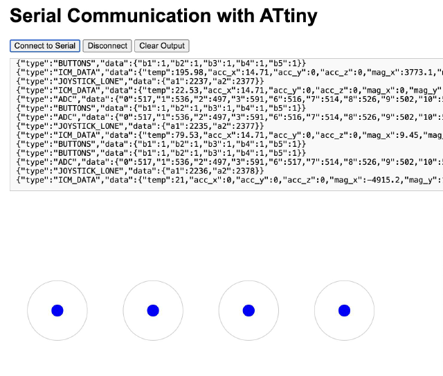
So now the problem is that the old board is too big and uses 2mm screws. I could design somethign new… or…it’s less than 12 hours until we start setting up, so I took some pliers to the model to clear out the little space I needed. I needed some release.
It actually fit in pretty well, even though it had the annoying horizontal pins. I used wire instead of dupont connectors, and taped it in. Well, I had one design for the bottom that was beautiful and nice, and if everything had gone to plan it would have been great, but this wasn’t so bad.
Tips 🔗
prototyping 🔗
Every time you produce something, even if it fails, see how many things you can learn from the iteration that will be useful for the future.
e.g. I cut a board but the mill was broken and was removing my entire trace. but i was able to measure that I had the footprint was correct for a throughhole screw terminal, though I needed to make two of the circles bigger.
muscle memory for machines 🔗
If you’re using a machien a bunch of times, it’s useful to develop some muscle memory for ways to double check things.
I get inspired by MTA, that always point at something, based on how japanese trains work.
So for the Carvera, I always wait for the laser to draw its boundaries before going back to work.
Other things 🔗
After learning about 3d printers, I realized I should finally get one. Was thinking as a reward for finishing the semseter, but realized it’d be useful.
You can save $400 knock a 1/3 off the price by building it yourself. So I spent a few hours for a week assembling it. It was legos. This was pretty useful to learn about building with 3d printers as well: all the different sizes of screws, tricks to assemble them, wire management, which things are heavy, stepper motors. So I don’t know, if you have the opporutnity, I think it was nice!
Week 14 update 🔗
less then a week left! I’m a few days behind where I wanted to be, but I finally got my “attiny1624 acting as a ADC for 4 of the joysticks”. (it’s slow…. because the last bit of code i was able to program to it set the delay to 500ms…)
(I’m using the totally wrong fingers, which I normally don’t do when I’m fidgeting with it… I think I was just nervous this would be the only video I get of it…)
This was made a lot harder because programming attiny’s using megatinycore+universal programmer is tricky right now from M2 chips on Mac. What (mostly) works is…
- setting up a Virtual Machine running Ubuntu Server (grab the arm one, the other one will fail to boot and not tell you why)..
- make life easier with your retina display and set it up so you can ssh into the virtual machine.
- use arduino to export the file as binary (I’m not sure which all are important, but I chose attiny3224).
- go find the hex file (open sketch directory, or look at what file it outputs. tip, you can go into settings and tell it to be verbose during compile and verbose to find t)h
- scp -p 2222 localhost to get it onto your virtualmachine, because i have some slight doubts that sharing folders actually works on M2 chips and this is fine anyway (you’d have to move the hex file anyway…)
- you’ll also need to set up USB on the virtualmachine, so that it forwards your device there.
- figure out what that device is called, it’s probably something like “/tty/ttyACM0”.
- in the virtual machine (i.e. ssh’d into it) “./venv/bin/pymcuprog write -t uart -u /dev/ttyACM0 -d attiny1624 -f file.ino.hex –clk 9600 –erase -v debug” is the command i used to get it on the device
i don’t know if i had to do this or if megatinycore does this okay, but you can also write fuses with “./venv/bin/pymcuprog write -m fuses -o 0 -l 0x00 -t uart -u /dev/ttyACM0 -d attiny1624 –clk 9600”.
phew, that’s a lot, but the speed boost i get from working on one machine has been worth it: worked through and got ADC to send the data through serial to another board.
Now here’s the problem: I start getting errors again after programming a few times. I somewhat suspect it’s similar to getting errors when I have too much serial writing on my xiao chips, where I need to hold down the boot button (because the board is still happily sending serial output).
I keep forgetting my USB-A to USB-C so I can use Char’s computer, to see if burning the bootloader again would fix things.
Also! I started playing with step response things. I wrote the code to time how long it took. I realize I probably built the sensor wrong: both sides are covered in epoxy, which is probably insulating it enough so I’m not forming any electric field? I’ll try it again..
I also picked up some TRRS 3.5mm cables (e.g. with 4 wires, usually meant for headphones with microphones, so they give you ground, left, right, and microphone). If I do make the second hand, I’m thinking I could use that to connect them together.
Absolute bare minimum
- video
- website
- answer the questions, get the costs…
- design the home board + “cover”
Probably going to do it before designing the “cover” (e.g. today)
- The boards keep falling off, and it’s hard to find screws. (maybe) redo the whole thing with M3 holes? and throughhole screw terminals?
- at the very least, probably good to redo the 3-finger board, since the dupont female connectors got filled with epoxy and I had to solder on more wires.
- update the “home” board:
- to have a second I2C or serial or something so I can talk to the other hand (that also means I could make the second hand just a passthrough, maybe with another attiny in place of the xiao?)
- try out IMU (at least have a slot for it!). This is pretty luxurious at $15, but will definitely make this a very fun controller for live performances.
- maybe add a tiny little board for the thumb region, 2x analog, click, and maybe 2-3 buttons… I think that’ll be more modular..
(wondering about switchin gto a 3226. that would probably let me handle the entire left hand with one chip.. (~14 gpio pins, 10 for joysticks, 4 for clicks.. hmm but maybe i’d want to make it extensible.. so maybe use a few of those pins for getting spi or something from another device? or wait, maybe just make it possible to plug in a xiao. ))
Here’s what’s left:
Wednesday (electronics-focused, in the lab) 🔗
-
Main goal: get the right hand end-to-end working with a correct “home” board, swap out any PCBs with new designs that I need to.
-
update “corrected adc” board using Intel laptop or Char’s laptop, and see if I can program it with the code that… runs more frequently (also should i wait for an initial message before sending data? should i wait for a message before sending data each time?)
- update the “home” board design (add IMU and second way to do serial/i2c, find a xiao that works.)
-
create a new set of boards with the other joysticks. I think I’ll use them for the right hand, and then desolder the others to make the left hand if I have time (in a few days). I already have the boards designed here..
- M3
- screw terminals
-
test new version of vinyl cut capacitive touch (ideally for left hand)
Thursday (fabrication-focused, at home until ~recitation) 🔗
- Main goal: iterate on the right hand base again in its (approximate) final form. plus prep for molding+casting (maybe a stand for the controllers?)
- Stretch: produce PCBs for left hand
- make sure that the migrated designs still work (I redid the designs again to make it easier to do the left+right hand, but I haven’t physically printed it yet.)
- I’ll know if I was able to create the M3 boards, so can update the design accordingly.
Friday (lab in afternoon?) 🔗
- Main goal: mvp application (learn keys? or viz if i only made one hand) + first pass on website, anything else from building… deadline for second hand
Saturday 🔗
- (other things, day off)
Sunday 🔗
- Main goal: website for MVP, video
Monday 🔗
- prepare what i’ll show
Tuesday (open house!) 🔗
Week 13 update 🔗
okay a lot of things!
I got a more-or-less final form for the body.
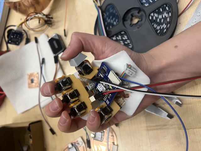
(the universal programmer is in there just to make sure I can fit the “home” board that I hadn’t made yet.)
I also am still bothered by the pinky, so I’m starting to explore capacative touch. Also because I can’t resist patterns of copper in clear epoxy..
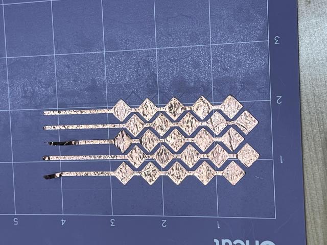
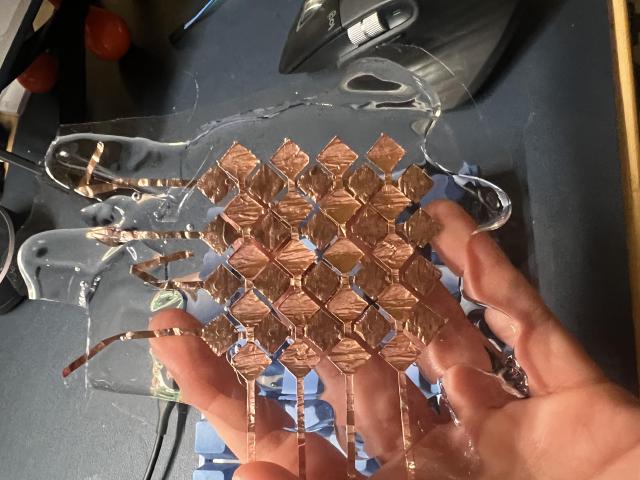
I haven’t tried hooking it up yet.. Some things I am already thinking of is that it is cold out, and gloves work on joysticks but not on capacative touch.. (and while some gloves have stuff in the finger and thumb, this is about the pinky finger.)
here’s what’s left
basics (to finish one hand):
- make sure wires all fit
- program the attiny (need to find a windows machine)
- actually get input from it…
full keyboard:
- need to add second I2C or something to the home board
- maybe build a left hand so i can start testing the keyboard idea?
more things
- test out capacative touch alternative for the pinky finger and fingers plate.
document :D
some other work 🔗
been meaning to drop in the twiddler

there are also a lot from Chorded_keyboard.
but i don’t have to be chorded, and i’m happier with two hands if it’s easier to learn.
Week 12 update 🔗
phew, I’ve been doing a lot of work here. I’m trying to see if I can get a first version all hooked together this week.
I was about to pivot from joysticks because I was afraid they’d be too hard to push, but then I printed keyboard keycaps and put it on the joystick, and instantly liked it more. I think it’s because of extending the lever makes them easier to push. I’m a little worried about spacing, but that’s what i’ll find out this week.
The cheap hall sensor joysticks just started smoking when I put them in the same circuit as the potentiometer ones. I’m a little confused about this, because it’s marked as a drop-in replacement in ps5 controllers (and maybe I wired something wrong). In any case, I definitely get different kinds of readings from the ADC, and I’m thinking I’ll try to stick with the 10k potentiometer joysticks.
I finally got Rust to work on a physical device! I’m not getting the weird error I was getting before. It does seem really nice and comfy to program in. But one thing was that the ADC calibration seemed a little off: it would only go from 2000s to 4000s. There’s a ticket about it, but I couldn’t quite sort it out. And 2000s to 4000s is fine with me.. when i get to the analysis stage, the model will calibrate it anyway…
The next challenge is dealing with 10+ analog inputs (2x per joystick). Most boards don’t have that many. The ATTiny does though. I’m trying out the (1614?) because I can fit 4 fingers on it, plus pins needed for I2C and UPDI. I’m thinking I can put the thumb on the main board.
Oh, here’s some documentation of the cad progress.
I’ve been modeling around the 3d scan, and printing out test runs. I’ve used this to figure out how the joysticks would need to be placed.
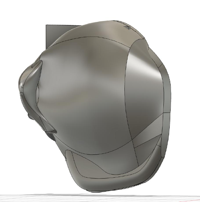
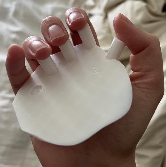
And then I’ve been trying to position the joysticks in. This helped me realize that I needed to build one board with teh three joysticks, because 3 separate boards would be too far away.
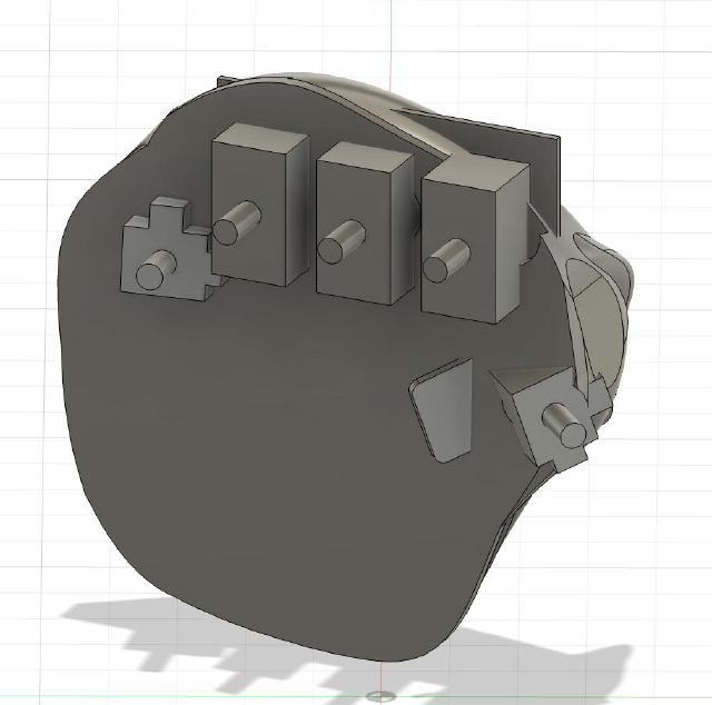
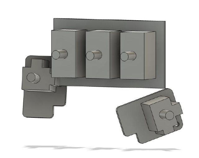
My goal this week is to try to build a very first version, end-to-end. I need to get the ADC thing working, design a thumb board (or just print the toggle if i want to skip buttons to start with), and then figure out how to mount it in the 3d.
midterm review 🔗
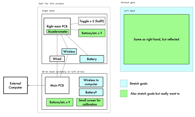
12/17 is the project presentation. Today it is 11/14, so I have 4.5 weeks to build this!
Week 1 (by 11/19):
- CAD the first draft of the body
- fabricate a first draft of the body (how much room for toggles?)
- explore flexures for toggles
Week 2 (by 11/26):
- build the wrist band.
- After networking class, try to network the (soon-to-be) hand to the wrist to the computer.
- Keep iterating on toggles (membranes?).
Week 3 [thanksgiving] (by 12/3):
- Either have toggles, or fall back on the mass-produced toggles.
- Build the first controller.
- Wire everything together
Week 4 (by 12/10):
- code a mvp (get data onto computer, and use it in livecoding)!
- build the second controller if there’s time
Week 5 (by 12/17):
- Testing and improvements.
- If already have a second controller, rpgoram the accelerometer and encoder for livecoding.
Build V1 of one hand
- CAD the body
- DONE molded clay and 3d scanned it.
- TODO I want to turn that into a smoother shape and 3d print it to see if it feels as good as the clay.
- TODO Figure out how to carve out area for the toggles/buttons, and electronics.
- Design a MVP for the wristband
- Develop V1 of toggles (is hall even viable?)
- DONE explore 3d printed ball-and-socket
- TODO make a hall sensor PCB board
- TODO 3d print flexures (tabs)
- TODO try “membrane”
- Develop V1 of the full system (does it work for typing?)
- TODO code up calibrating software
- TODO do sensors interfer too much with each other?
Nice to haves:
- second hand
- battery
- wireless
Log 🔗
(This page moves back in time as it goes down!)
As of week 10 🔗
Here’s a doodle
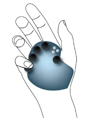
I’ve molded it in clay and then 3d scanned it, so now I could make a prototype to sort out the form factor.
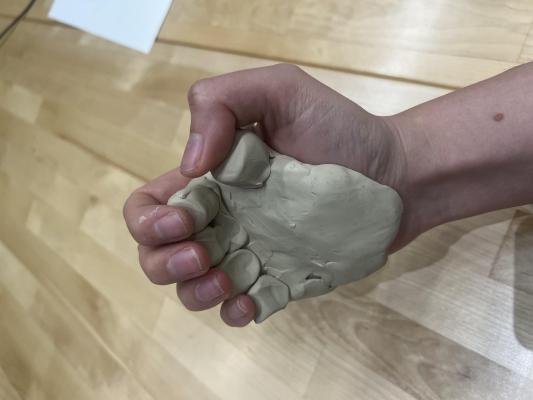
It was interesting to try to adapt the shape to my hand because my hand would try to adapt to the shape. I had to try to fight that, and adjust it until it was comfortable.
Ergonomics 🔗
- What is the palm shape
- how much should my fingers bend to reach the toggles
- how should the thumb area be laid out
- how to attach it to my hand (lingdong uses elastic festival bracelets!)
- weight distribution
buttons 🔗
- can i get toggles to work?
As of week 9 🔗
So here’s the idea:
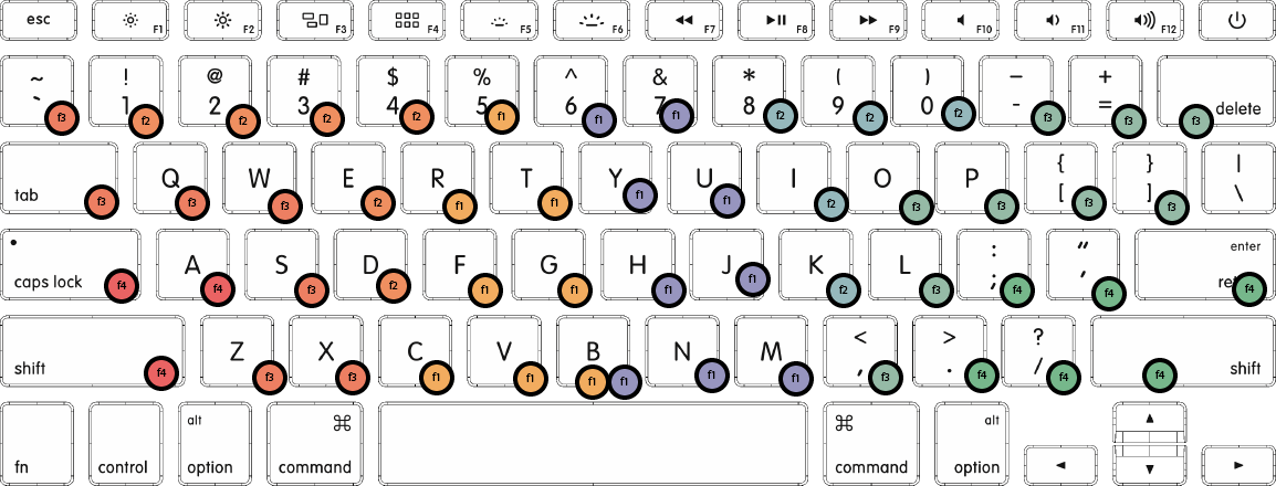
- it would be like the switch controller (or I guess VR handsets) where you hold one in each hand. That’s sweet, because you can position your arms and wrists at whatever angle makes sense.
- I don’t mind learning a few new keys, but I think for qwerty I’d like to be able to draw on my muscle memory.
- ideally you could quickly move it out of the way of your thumb and forefinger, in case you need to switch back to the trackpad or do something in the world.
- it would be ergonomic to my hand, so I can shape some clay and 3d scan it. (I found a Youtube video where they used colorful playdough and iPhone 3d scanning.)
- I’m thinking if the finger-controls could be mostly 3d printed, so I could replace them and adjust them.
- I might throw a few more sensors in it that I could use it for livecoding.
I thought about whether to source ~10 joysticks or to build them.
I had one idea of trying to build cheap PLA joysticks that I could insert a magnet into (probably by pausing the print) and use the hall effect sensor. The hall effect sensors would be more permenantly installed, but the joysticks could be attached and removed as I needed to iterate.
So I started to experiment with 3d printing ball-and-socket joints, just to learn a little more. I saw you could 3dprint stability springs, so I designed a ball-in-socket with stability spring.
After adjusting the spacing between the ball and socket, it did start to move, though between the springs and the roughness, it feels like they’re full of fingernail clippings. Maybe it would work, and maybe a Resin printer would give a smoother feel (though I’d love for it to work with PLA).
I also wonder if I could build a different mechanism
As of week 8 🔗
Well, input electronics week got me thinking about pivoting pretty dramatically. I was on a bus to NYC, and positioning my hands on the keyboard and trackpad was not ergonomic. I wondered if, given I could make almost anything, if I could make an improved keyboard.
As of week 7 🔗
This was a week I’ve been looking forward to, because I was thinking of casting a bunch of lenses/things for it. But I realize using a lot of plastic (or even acrylic) matches some of my safety/environmental ideas. I’ve been wondering if bioplastic could be interesting, but creating an entire surface in this might be tricky.
On the other hand, i did like the shading of the tiles, and maybe I could switch things up: rails holding lights a few inches off the surface that face the piece. If I put tiles down, it would make for an interesting effect with colors.
It also could help out with the idea of attaching the orbs, though i’m still working out how that would work (maybe they could just latch on to the rails?). The rails are also interesting because maybe you coudl tap the orbs on the bottom of the rails to change the action.

Aside from that, I redid my board from week 6, and it is more likely to function at this point. I’ll actually test out the RFID soon, which will be important to figure out where to put the tags.
As of week 6 🔗
So to add a diagram, here’s a schematic of the set up.
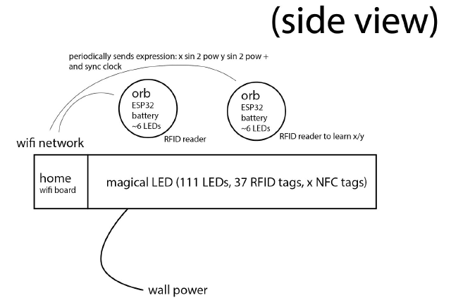
I guess another interesting part is that it’s a bit of a fractal: I want to put a screen on one of the orbs that shows a more detailed view of what that section of the sculpture is showing (and phones+NFC is another way to access that view.)
Printed the dev board designed last week, so hopefully I’ll be able to start testing out the RFID readers.
I also saw that someone I know has been making hexagonal LED walls, with some interesting diffusion.
As of week 5 🔗
No major updates here! The board I laid out for w5 assignment should make it much easier to test out the RFID boards (and hoping I can get my hand on a ESP32 or two.)
I’ve been keeping my eye out for lenses: most lamps have something going on in plastic. But it seems like molding clear plastic is tricky. But alsoo, I don’t really want clear plastic, I want some sort of diffuser. Molding and casting is coming up in two weeks, though I’m tempted to start setting up some parameterized 3D models for the textures.
As of week 4 🔗
Phew, so last week was a lot of work on the final project with the implementation of an embedded Rust version of a expresion language.
I didn’t work directly on it. I am kind of going back and forth about whether to go back to the 3d sculpture idea (but it’ll be a lot of work to create all of the sides, and I might in turn lose some resolution I’d like to have. Not to mention the RFID tricks sound fun but would be hard to manage.)

Other than that, my only other update is that I’ve received the RFID tags and some boards to play with, and I accidentally ordered 6 RFID instead of 3. So that might be fun. And my RFID stickers don’t seem to work with NFC, so I might need to order separate stickers if I want to do both.
As of week 3 🔗
(This was originally on w3)
My updated plan is an LED-backed surface. The LEDs will adjust brightness (maybe color) according to a programmable interface (probably a website, but also probably live-coded?? another dream was a physical controller, but that’s low on the priority list). But that’s not all! On this surface, there will be RFID chips. I’ll also build orbs. The orbs might have denser LEDs or motors or sound or thermal printers or… When the orbs are placed at different locations, they’ll join the pattern with their custom contributions that also depend on their locations.
(graphic created using a browser version of weird live code framework I use)
The circles are where the RFID placements are, but are otherwise just for show: I’m also thinking of having denser LEDs (e.g. 3 per circle), and having an assortment of different diffusers: some could be a full circle, some could have separate areas for each LED, and others could be holes in wood. And some wilder ideas, like some diffusers could have half of them covered by polarized plastic, and an orb could move another polarized film in front of them.
This is interesting to me because it goes along with my live coding work (the aforementioned live code framework) but with a completely different interface. I can start with something for this class, but I could keep tweaking the code. I also like the (reasonable) challenge of embedded Rust, since I work a lot in regular Rust and am maybe finally starting to understand 40% of what people are talking about in forums. The physical project means I can try out a few things I’ve never done before (molding fun LED diffusers? Using a CNC machine to make a cool frame?).
After briefly chatting with Quinten during office hours, my current thought is that each orb will contain an ESP32 chip to chat with the home computer, an RFID reader to register its location, a battery, and then whatever special thing the orb has. (I originally wanted to have an excuse to use ATTiny, but because I want to wirelessly update instructions, I probably need ESP32s).
Another thing I’m not sure about is synchronizing clocks. I don’t know how sensitive the project will be to it. I imagine I want them mostly synchronized, but since the objects will be different sizes and in different places, will I be able to tell something is off if they’re running half a second behind?
I’ve never worked with RFID/NFC before, but I’ve seen the little metal spirals that come in books I’ve bought. So the metal spirals are pretty inexpensive relative to the price of a book. It’s probably an RFID chip, and that’s where I could store information about what position the object is resting. Then there are readers (which sound like they can also write). It looks like RFID readers are significantly cheaper than NFC readers, and will work for my purposes. Since that might not work at all (distances, etc), I snagged a $10 set of 4 RFID readers and a $15 pack of supposed RFID+NFC stickers off of a (retail website) so I could do some proof of concept testing in the next couple weeks.
Also, Char showed me magical dice that have NFC chips in them, and you can use your phone to open a website that shows which side of the die you tapped(!). That makes me wonder if the RFID indeed also works as NFC if tapping a part of the installation could open up a glitch.io page that’s also synchronized to the main computer, so your screen joins the installation. (and maybe something can happen when you walk away, or if you take an orb away from it…)
Early thoughts 🔗
I have some early thoughts in w1-cad.