This week was all about computer-controlled cutting, featuring the laser cutter and the vinyl cutter.
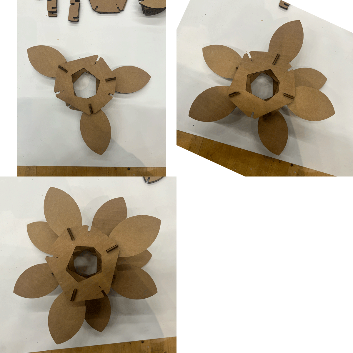
To create this, here is the dxf: [link]
Shop and laser cutter training 🔗
To use the laser cutter, we need to be trained! Wedyan taught my session. While I have used a laser cutter before at ITP Camp, there were a few differences like needing to manually focus the laser. Focusing the laser is important because a laser beam has a “waist”, which is (usually) what you want to hit the material. Some machines automatically adjust (I think the ITP Camp cutter would), but CBA shop’s particular laser cutter needs you to drop in a little rod to a hook on the head, and then adjust the bed along the z-axis until the rod lifts off the table.
(Reading posts on the internet helped me answer a few questions: like how deep the waist is (it seems to depend on the lens). The page also talks about mirror alignment, and includes some demos of what happens when the laser isn’t focused.)
Another difference is the settings to cut things: a hairline maps to cutting and anything else might be engraved (so back and forth like a printer). We got a fun question about ordering cuts: if you need to cut out internal shapes from an outer shape (like a donut), it’s good to cut out the internal shapes first, or else the outer cut will let the piece jiggle around while you cut out the inner details. Wedyan said there doesn’t seem to be anything automatic with this machine, but the trick with “selecting only what you want to print” is a good way to tackle that.
Idea 🔗
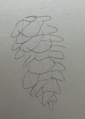
Cardboard reminded me of pinecones, so I wanted to make a pinecone lamp. While a lot of illustrations of pinecones draw their scales lined up exactly diagonally, the scales are offset a bit. The arrangement of scales on a pinecone (or leaves on a plant) is called “phyllotaxis” and there’s a nice write-up on how to implement it in this book. So! I want to create a modular kit that allows you to arrange units (or petals) following phyllotaxis.
Starting with Fusion 360 🔗
I’m not sure how deep I want to go with Fusion 360, since I also create a lot of things with code and I’m not sure where I want to do the hand-off between them (do I want to depend on a third-party closed-source system that wants me to be online to do my work?) For example, I avoid using Inkscape/Illustrator to fine-tune my pen plotting when I can, because it’s annoying for reproducibility. Most of the time I’ve been like “I can do this real quick in Illustrator!”, it is not quick, and then when I want to rerun my code, I have to do the Illustrator work all over again.
But I finally settled on trying Fusion out anyway. I start by just doodling, trying to remember the steps to create the cool linkage Miana had made in the recitation. I put on a YouTube tutorial and it is over my head so I try to create one of the shapes. I get confused by how sketch parenting works, and then finally give up when I do an action and create an impossible shape:
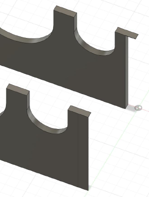
(I’m a little self-conscious about how easy it is to glitch out-of-bounds in the programs I write, but seeing professional software makes it easy to do the same thing makes me feel a little better about my programs, but also a little more gloomy about how hard software is.)
The Plan 🔗
So that was enough Fusion for now. I go into my comfort zone and make a very silly little program that fakes being 3d.
I now know roughly how this will look, so I go back to Fusion and draw out the layer shape. In this version, I want to try having five petals per layer. The inside shape will be used to align layers, so it includes notches for the first three ribs from this layer and the last three ribs from the previous layer.
Prototyping with the vinyl cutter 🔗
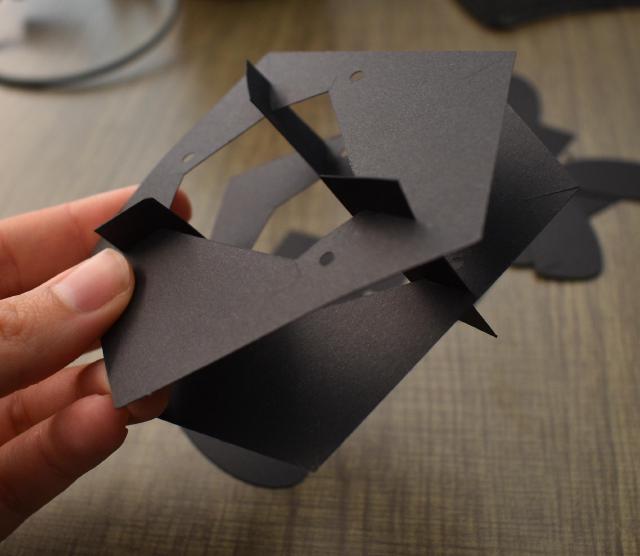
I already own a Cricut for my creative coding endeavors. If I use the parameters (yay for parametric design) and shrink down the notches to be thin enough for paper, I can build a few sample models to get a feel for the structure.
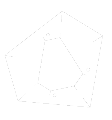
I export the shape as a DFX, load it into Illustrator, and, it’s just a line.
I wonder if it’s projecting onto the wrong plane. I find a YouTube that tells me to export differently. I extrude my sketches, then select the components and create a new sketch, select the faces, project, right-click the sketch, and export that as DFX. I load this into Illustrator, but it is way too big. I reload, but this time set “1” to mean “1mm”. (Maybe that’s what was happening before too…)
And finally, I’m able to open it in Cricut. For once, Cricut’s default of “arranging all these shapes on the sheet” actually saves me time.
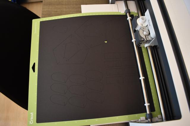
The machine caught a bit where I had two shapes too close. I don’t think cardboard will act the same way, so I’m not too worried.
CAD Office Hours and Fusion 360 makes more sense now 🔗
I went to office hours with Alfonso, who showed me how to use Dimensions and parameters. I had been trying to use constraints for everything and would overconstrain the shape. So this instantly made Fusion more usable!
Another prototype 🔗
In the previous version, I used notches in the “petals” to adjust the z-location of the petal, so there were 3 distinct petals. After holding it in my hand, I realized I could move the “ribs” to the outer perimeter and use them to attach the layers and to set the z-location of the petals. This isolates the complicated “how exactly should I connect things?” to building the base, from the modular/fun “what petals do I want.” I’ll return to this when I assemble the piece!
I also started to think about how to account for kerf. I worry I’ll need to adjust all of my parameters to account for kerf, but think there must be a better way. I basically need everything to extend outwards by the magic amount. Worst case, I might be able to do that in Illustrator, but there should be a way in CAD.
CAD again 🔗
I went home and started drawing out my new shape. Here’s roughly what I came up with.
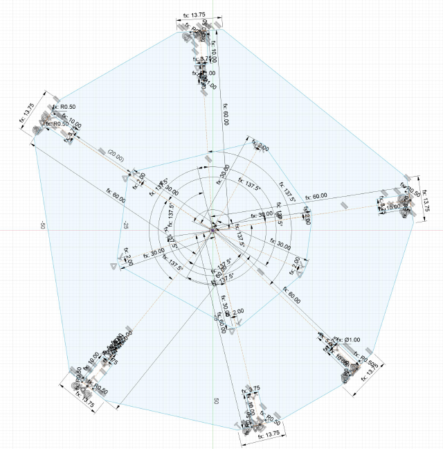
I’m sure I’ll look back and see plenty of ways this could be simplified, but I’m happy I got something to work. Here are a few tips I figured out along the way.
- Watch out for spooky constraints that appear as you draw. Especially ones like “Force this line to be horizontal/vertical”.
- Add constraints, and then jiggle it a bit and see what’s broken. For example, the thing I was drawing should only be allowed to rotate, so this was a quick way to find out what had the wrong constraints.
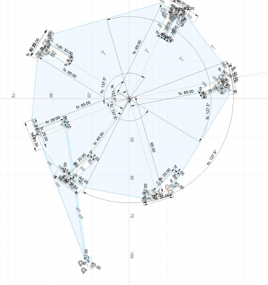
- You can change construction lines to real lines, and go back and forth. I think keeping constraints on the construction lines is useful. I suspect my rounded corners (chamfers) broke some of my length constraints.
- I still don’t know the best way to have many lines on top of each other (e.g. I have one to measure 7mm along the distance along another line.) You can long-click to get a dropdown of lines to select.
- I’m also not sure the best practice for what to do if there are multiple solutions, e.g. something can be perpendicular in two ways, but maybe you want it to be on the left/right. (Now that I’m writing it out, maybe I can use an angle dimension and specify 90 or 270.)
- I do still need to figure out how to clone parts. Like the notches, all should look the same, but now I have to manually go through the notches and make sure they are lined up right.
Group project 🔗
Speaking of the magic kerf amount, at this point a group of us met up to complete the group assignment.
We set up a few 50mm squares with hairline stroke width. They are black (#000000), red (#FF0000), and green (#00FF00). We’re a little surprised by the suggested power/speed combinations: in my experience with cardboard, you usually set a fast speed and low power. In this case, it’s 100% power and what seems like a low speed of around 2. So we set the last box to that amount, the second to 2x the speed, and the first to 4x the speed. That way if it does burst into flames, we get a few good cuts done first.
We tape down the cardboard, focus the laser, do a dry run to make sure we’re cutting in a good spot, and then close the lid and gather around to watch it cut (but not watch too much because lasers aren’t great for your eyes).
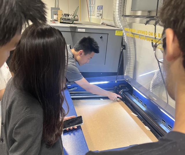
To our surprise, the only one that cuts all the way through is the recommended speed.
Now to calculate the kerf. We measure the square, which proves to be difficult: it’s a slightly different height than width. Our best guess is 49.9mm, which means the radius of the laser is 0.05mm. This will prove to be a questionable measurement in a moment.
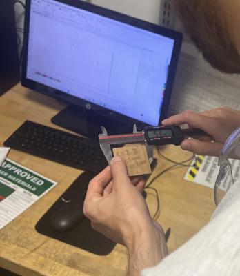
Jonathan had prepared a comb: the first notch was the supposed thickness of the cardboard (4mm), the next adjusted down by a small amount, and so on. We’re trying to get a press fit, so we want it to be tight.
But to do this test, we need to use that kerf calculation so the laser doesn’t cut out the wrong sizes. We figured out that we could use Fusion 360’s “offset” tool to make the outline 0.05mm farther out. We cut the comb, and measured out the gap that should be 4mm.. and it’s 4.2mm, huh. Well.
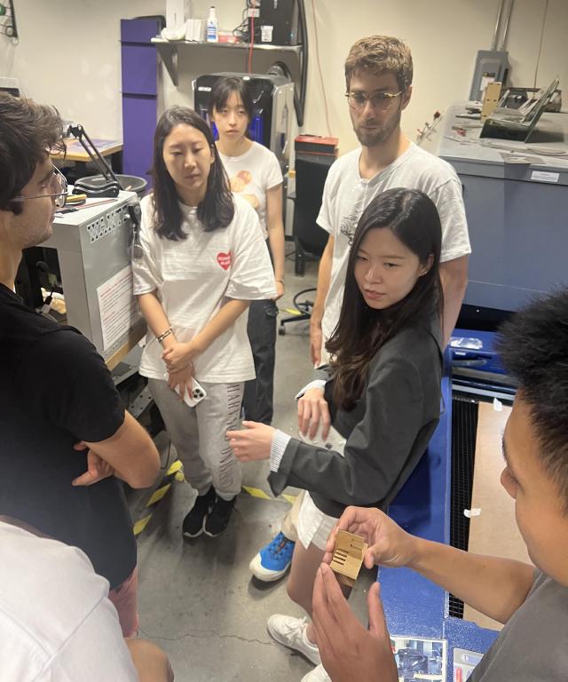
Even so, we can still use the comb to answer our question. Testing the different gaps, we find the one corresponding to a true size of 3.7mm seems to be the winner. I’ll start using the measurement of kerf of 0.1mm going forward. We also try out a chamfer version, with rounded corners to make it easier to slide the pieces together.
Finishing the individual assignment 🔗
With a rollercoaster of a laser cutter fire that was successfully put out and a melted belt that was heroically replaced by Hannah and Quentin, we met up and started queuing to use the cutter. I made a few more adjustments to my design: I wanted different petals and decided to go with a simple vesica piscis (intersecting two circles so the center of each lies on the outline of the other) petals. With a plan to start with an obvious flower and work up to the abstract shapes.
And finally, I laser-cut the cardboard! I set the magic parameters we’ve determined.
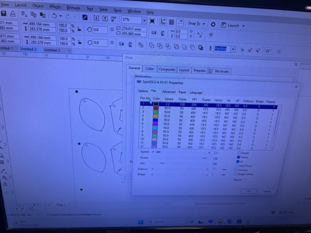
I tape down the cardboard (the machine’s focus is already calibrated for this cardboard) and start cutting.
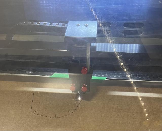
Admittedly, it could have gone a bit better, but it’s okay. After all of the careful centering of the label circles to center lines, I somehow move the dots in CoralDRAW. But the cardboard stock is running low, and the line to use the cutter is getting long, and the error is not particularly visible, so I go with it. I also don’t set the printer document size correctly, so it crops some of my petals. I add a few extra petals to the bottom, and they go off the bottom edge. But I end up with enough pieces. While I had added chamfer, I forgot to adjust the parameter for the cardboard so it’s microscopic and basically useless.
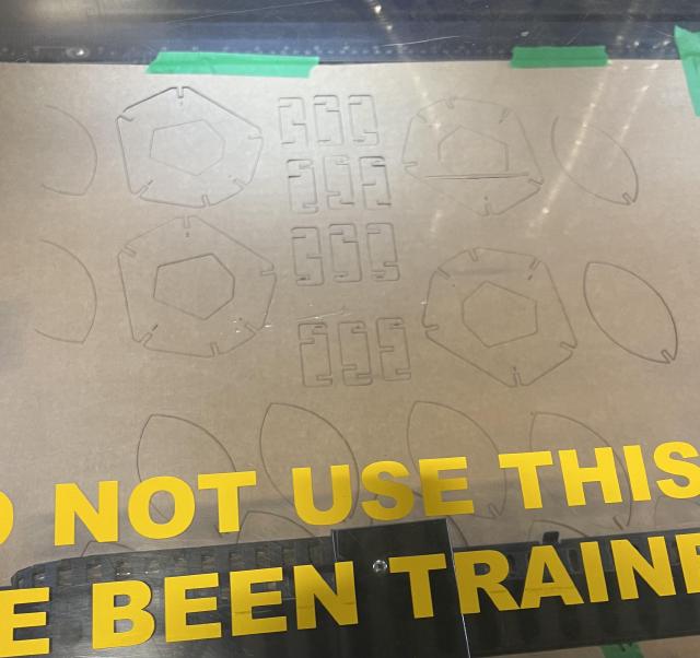
But it’s still exciting to see the kit all cut out.
Assembly 🔗
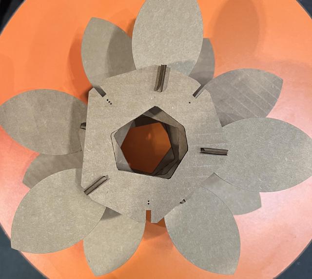
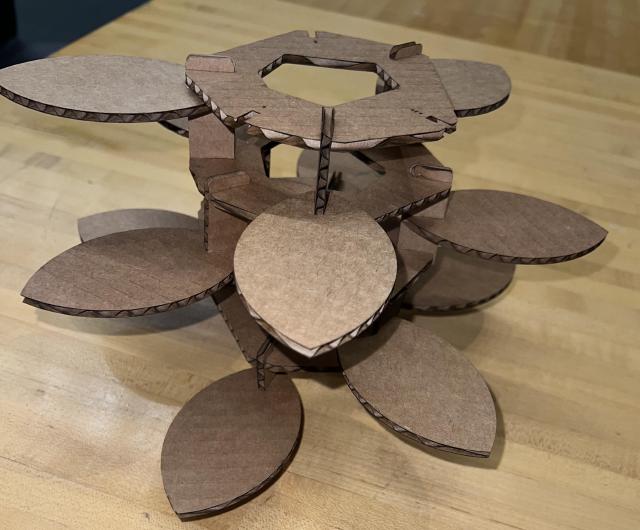
I’m pretty proud of this, given I haven’t done much physical object design! So here’s the goal: each petal should progressively raise along the z-axis by a fixed amount and swing around the z-axis by the magical “137.5 degrees”. If it was a lot denser, I think it would correspond to figure 4.11 in the chapter on Phyllotaxis.
The way I did this was to make a series of layers held together by ribs. Each layer is “responsible” for the next three petals above it. (the top layer can optionally just act as an end-cap).
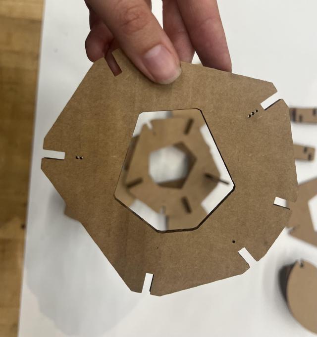
The ribs will help set the z-position of a petal in that layer and also help position the next layer so that the petals will start in the right place. Because their position is important, they have markings on the bottom (one to three little circles that can be cut with the laser cutter), so you know where to put them.
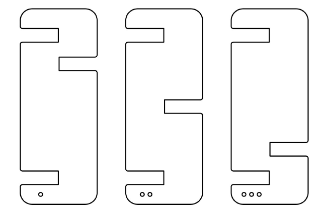
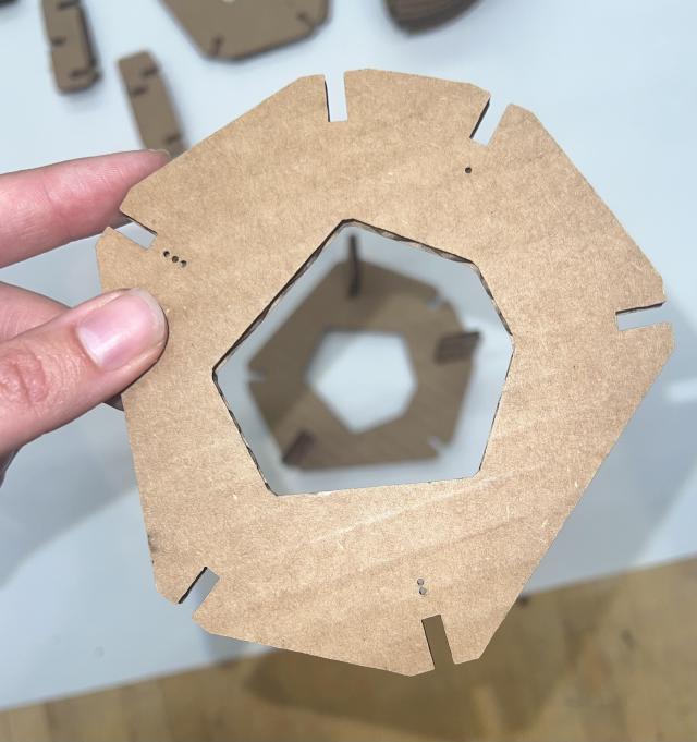
The layers guide where the ribs are positioned. Because I need to both add the petals for this layer and attach them to the previous layer, I end up with 6 notches. Each notch is exactly radius distance from the center, but instead of using the full circle, I cut out the polygon defined by the notches’ locations because I think it looks more interesting.
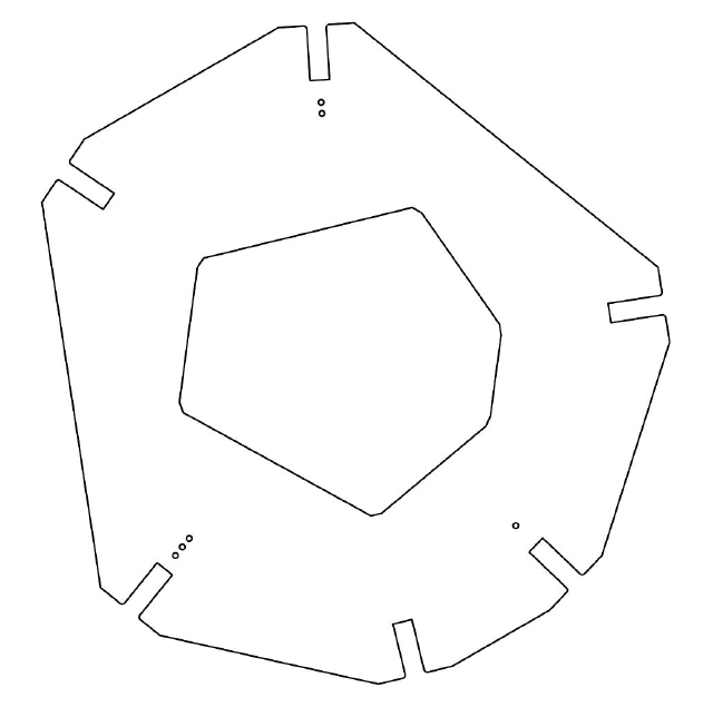
The layers include the instructions to attach the ribs. I mark the layer’s three notches with their corresponding circle patterns. To line up the next layer, I cut out the same weird polygon in the middle, so you can peer through it to align the next layer.
This is modular in two ways: you choose how many layers to include. You can also pick your petal types, though I only include one in the initial kit.
Here’s how it looks! First, you group together the pieces to make your life easier. The different types of ribs are to the left, layers are in the middle, and petals are to the right.
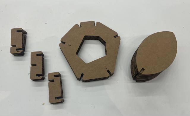
Then you match the ribs to their notch. You might just put one in to start with.
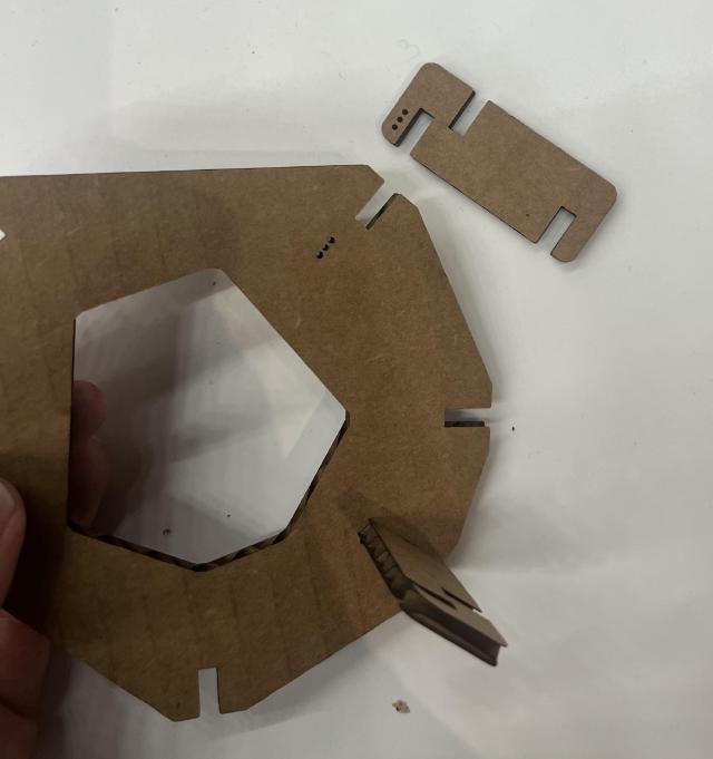
Pick up the next layer, and peer through the center to align it.
And use the ribs to connect the layers together.
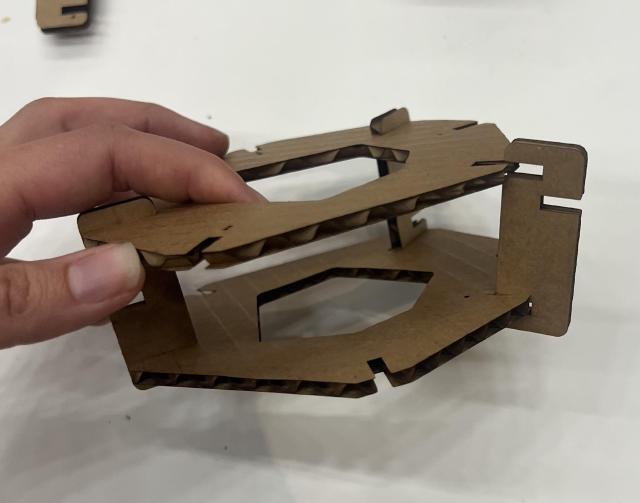
You can start adding petals.
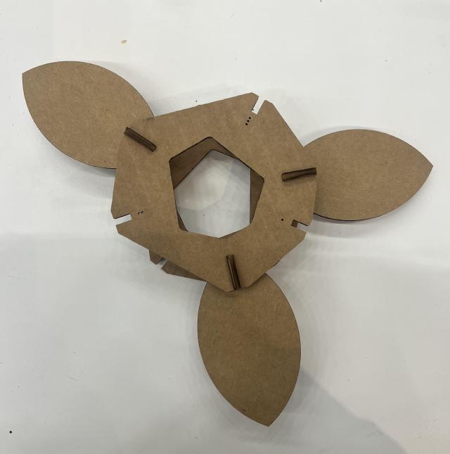
And more layers in the same way, peering through the cutout and using the top layer’s dots to tell you where the ribs go.
Result 🔗
Here’s how it looks!
Appendix: Assignment 🔗
From the class website:
group assignment:
do your lab's safety training
 characterize your lasercutter's focus, power, speed, rate,
    kerf, joint clearance and types
individual assignment:
cut something on the vinylcutter
design, lasercut, and document a parametric construction kit,
    accounting for the lasercutter kerf,
    which can be assembled in multiple ways,
    and for extra credit include elements that aren't flat