
3D Printing 🔗
I haven’t done much 3d printing, and I thought it would be cool to 3d print some of my generative work for the first time, but I had a surprising amount of trouble finding something that would be “hard to do with subtractive methods.” I flipped through my mood board things and realized I really like 2d stuff that looks 3d but isn’t actually 3d, with lots of colors, and lots of little details that would break. Another hangup was that I don’t have a good idea of how 3D printed structures hold up: what details break, what textures different the 3D printing process produces. I looked at other people’s assignments in previous years, and folks linking to this instructables. So I thought to take one of my 2D patterns based on cell divisions and connect them with the little torus + stick combinations for the hinges.
This turned into a lesson in Fusion 360. I used the repeating pattern tools (ended up using the rotational symmetry one instead of the rectangular pattern, because some things didn’t line up.) I redid things a few different times and learned to love the timeline feature for fixing mistakes in the past (a misplaced hinge) and then recomputing.
Getting ahead of myself. So first, I started with a pattern I had generatively produced. It uses a context-free grammar to define how a cell should divide and then uses some physics simulation to move the points around a bit. It was based on chapter 7 of The Algorithmic Beauty of Plants (can you tell that it is one of my favorite books). When I added the physics simulation a few weeks back, I wondered if the resulting shape would tile nicely, because it almost looked like it would.

So I opened up SVG, deleted some of the guidelines (since I normally use this for pen plotting), and then tried to center the shape… and I don’t know what I’m doing. I went back and watched some of the tutorials Alfonso recommended, and came back. A few things I ran into: the SVG is imported as green, so it’s fixed. You have to unlock it before you can mess with it. When extruding things, make sure “new body” is selected and not “join”, or they’d end up as one part. I also realized I was having a lot of trouble with the Move tool because it would be selecting Faces instead of Bodies.
I started by trying to add a constraint to treat the top and left edges the same as the bottom and right edges respectively, so it would have to tile nicely. I got as far as labeling the points so I’d know which pairs to constrain.
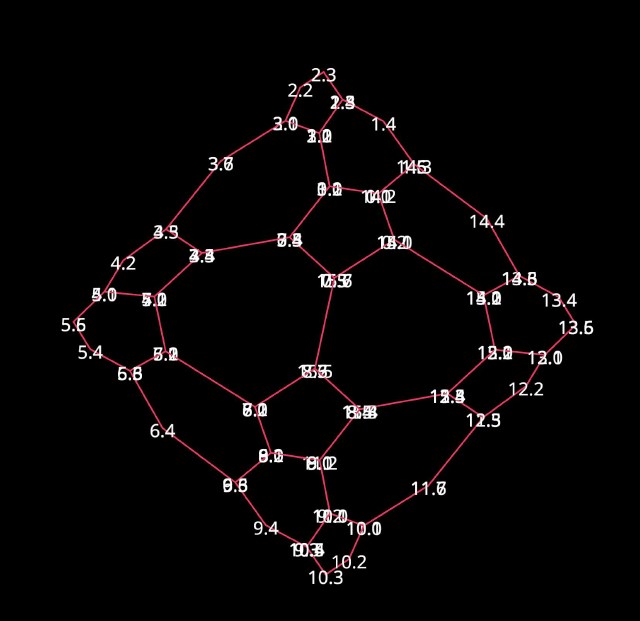
But after some time trying to get the program to run again after some refactoring I had done, I cut my losses and brought in the non-constrained version to fix in CAD. I also backed down to one with fewer recursive calls.
I removed half of the pattern, which should be the same with 180-degree rotational symmetry around the center and would save me some hinge placements. While I started by staying as close as I could to the generative result, I ended up putting CAD constraints on things, and then moving them until it looked similar.
Given that, there is a set of constraints to follow to make this work: so let’s start with the left and right edges, which have 3 line segments. If the top and bottom line segments are both parallel and equal in length, if you rotate by 180 degrees, the edge will fit together with itself. For the top and bottom, these will be rotated and then translated (so the top will join with a rotation of the bottom), so the two left-most segments on the top need to match their corresponding ones on the bottom, and then the bonus segment on the top will match to itself. (to be honest, I don’t remember if I knew what I was doing when I managed to make the last edge work so nicely, with that bonus parallelogram.)
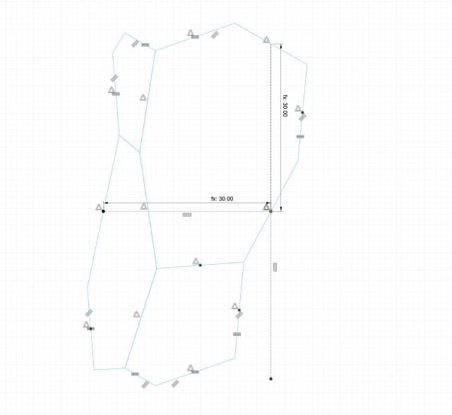
And given that, we can start to tile it! I marked the center of four faces and then rotated around the first one.
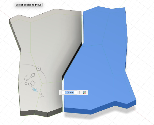
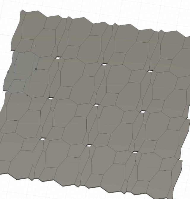
At this point, I tiled them rectangular along the XY plane. One of the constraints was the width and height of the pattern (picking any two points that would connect, the rest of the squiggle should be the same).
un-unhinged 🔗
So the part that made this hard to do with subtractive methods is that I’d print hinges in place, then break the supporting material so that it would be a little flexible. I created a new component for this.
I redesigned the hinge from the tutorial, using a pipe to draw the stick instead of the loft tool, and then splitting at a horizontal plane to remove the bottom (while it did look a little nicer and spoilers that it worked, I do wonder if the loft tool would make it stronger or something because the cap would be horizontal?)
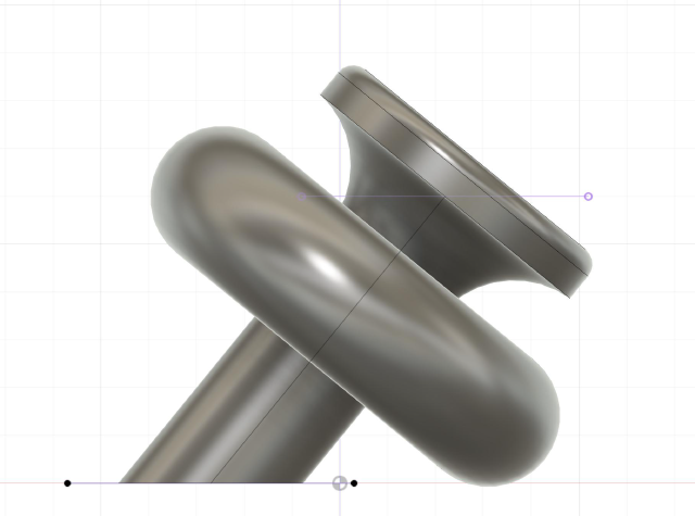
The instructable told you places to put the hinges that were specific to the hexagon but for mine, I needed to place it in different places.
I ran into a lot of trouble with the transform tools, since they would start to rotate around a different axis. So I projected it onto a plane and marked where the torus and stick crossed with a vertical line, as an arbitrary place where the edge should go (I used the bottom of the shapes, but maybe I should’ve used the center of the shapes. ah, I think because the torus and stick was the same width it’d be the same). Then I very methodologically did a series of steps: create the copy and rotate the hinge around the midpoint-axis so that it would align. Then use the point-to-point tool to move from that same midpoint axis to the midpoint of the two planes. (if you moved it first, so that say, you could see align it nicely with the angle, I kept losing that midpoint point so the point-to-point thing wouldn’t work). (another note is that I hadn’t added the gap between the cells yet, so I could use the midpoint)
But what was nice here was if I needed to rotate one of the hinges a little more, I could use the timeline to go back to that step, and then rotate, and then go back to the location on the timeline.
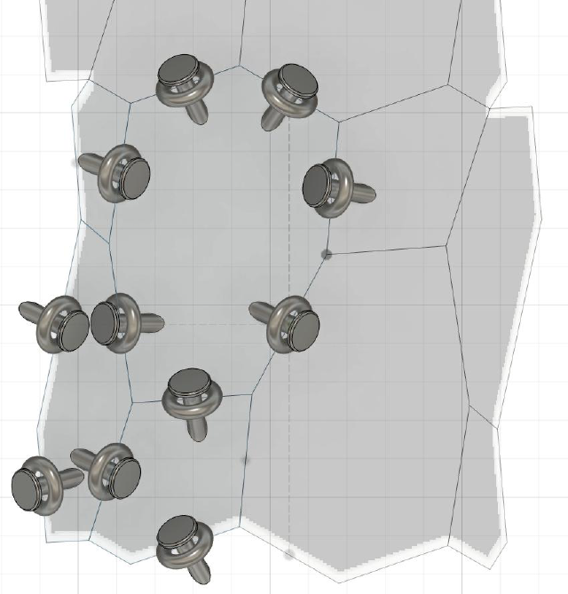
(thank goodness I had gone with the simplest one, instead of trying to do one more level of recursion)
Then I used symmetry to create the rest of the hinges. Note that a few of the hinges around the parameter would overlap, so I just didn’t include those in the cloning. Interestingly, the rectangular repetition didn’t place the hinges in the right spot (maybe the dimensions of the joint shape were different than the face shape?), so I had to mark the center of the design to create an axis to repeat around and do the hinges using only rotational symmetry.
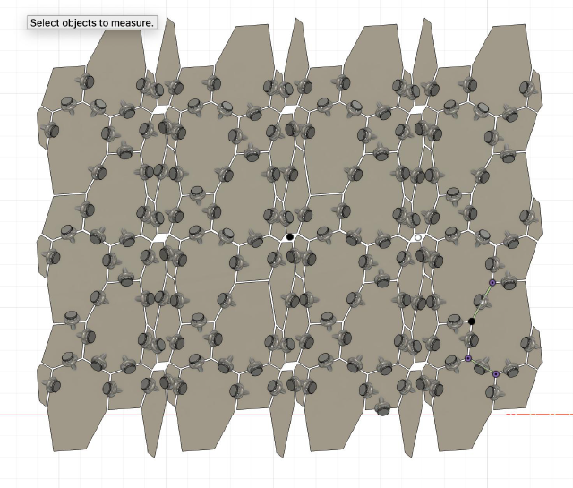
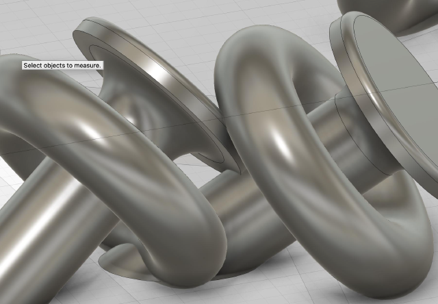
There were some places where I had to move the hinges so they wouldn’t fuse together, but still, it wasn’t perfect.
Simulation 🔗
I’d been worried that this wouldn’t bend at all, since I was totally guessing where to put the hinges and didn’t know how much play they would each have. If I had more printing time, I could have printed off some examples to test it out, but ah, I was eager to see the result anyway and maybe it would be an interesting failure for the Neil table.
There was one more thing I could try: simulation! I watched this chain tutorial. I imported the object from Fusion360, turned on physics, and turned the collision to a mesh because a convex hull would definitely make things bounce around. And, the thing fell like a brick as one object. I asked ChatGPT for tips and it told me to split up the objects, so I reran it and..
Yes. Yes. This is an accurate depiction of what I expect to happen when I 3d print. (the dots near the origin are because… I mistakenly thought that points were always construction lines, but I guess they show up in these files too.)
Printing 🔗
Okay, let’s print it. I load it into a slicer. After some trial-and-error (or rather, comparing my filenames to those on the USB drive), I figured out I needed to choose the MK 4 Input Shaper. I nearly forgot to update from PETG to PLA, but caught that based on the names too. I tapped around the screens on the printer, and it did tell me some details, but surprisingly was missing others..
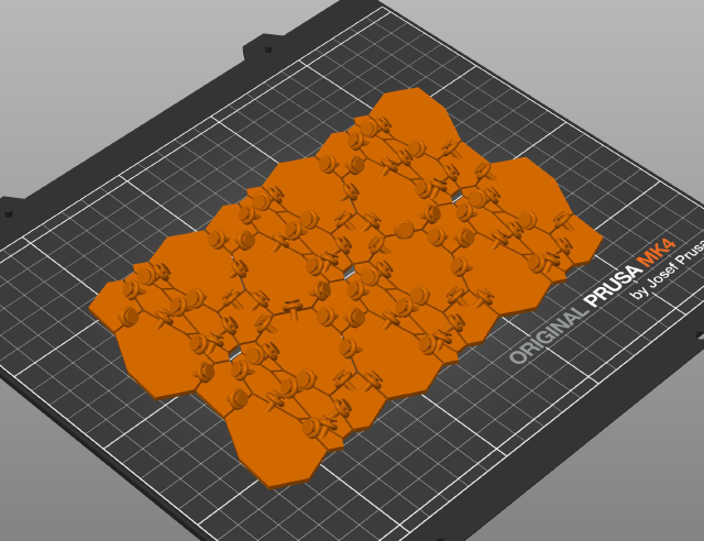
So it started to print
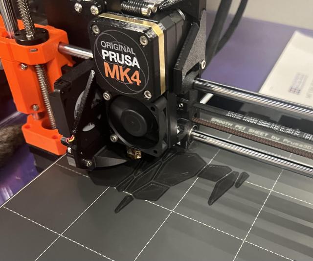
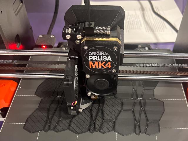
Once the first few layers had finished, I left to eat lunch outside in the sun. When I came back 3 hours after it had started, it had successfully finished a few minutes earlier and had cooled down enough to remove it.
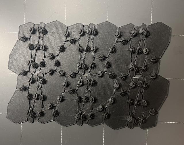
And I could remove it!
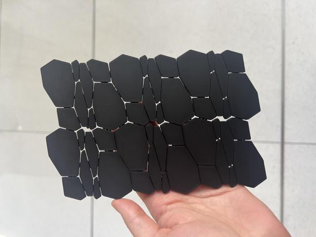
I brought it back to my lab and started to bend it to try to break some of the supports. The sticks and toruses were a little too fragile relative to the supports, and I did break one off entirely, so I took a break from removing the support materials.
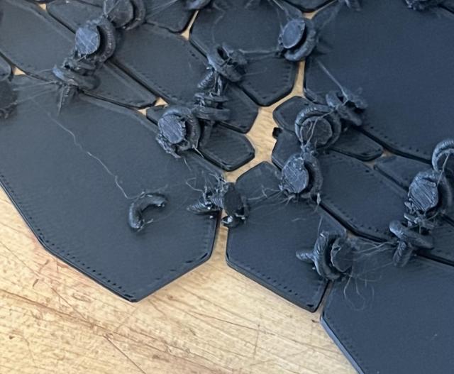
But it does move a bit!
3D Scanning 🔗
(Note: I used Gaussian splats, which are harder to turn into 3d objects. For the final project, I did more practical 3d scanning to get a 3d model.)
Char from my lab was working with Gaussian Splats, so I wanted to do the 3D scan with that work. She shared a nice tutorial for getting the Gaussian Splat data. I took a video (locking AE/EF), trying to walk slowly around. (This is just the first few seconds of it.)
I installed colmap (Char warned me that I needed to use the older version 3.8, so I cloned the repo, checked out the code tagged v3.8, and built it from there), split up the video into pngs with an FFmpeg command Char gave me:
ffmpeg -i IMG_8650.MOV -vf "select=not(mod(n\,5))" -vsync 0 water%04d.png
(After reinstalling ffmpeg, because installing colmap’s dependencies messed up my installation). I cloned the gaussian-splatting repo and ran through the first Python script, convert.py which, runs colmap. I can then open the results in the colmap GUI (I tried to open a folder, and it told me it needed to have points3d.bin, so I found a folder that contained that), and get this sweet representation of where the camera moved and the start of a representation of my water bottle.
Next up is training the Gaussian Splat model! Much like how other folks let a computer program a lot of this code, I handed my data over to Char who already had the model installed on her computer, who trained the model. Here’s a screenshot she sent me of the progress.
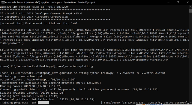
I got a .ply file. I loaded it into Blender, and at first, it looked like a mess of points, then I zoomed in and it looked like this:
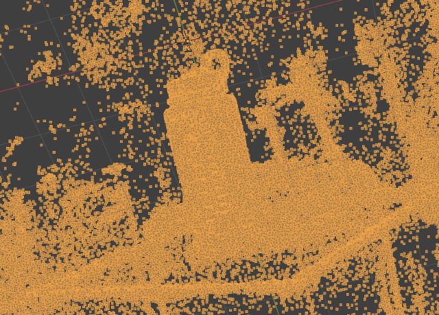
There’s my water bottle! But this isn’t a Gaussian splat. I looked around a bit, and then Char told me she had written an OpenFrameworks plugin for them! I downloaded her add-on from here. I followed the README along with the OpenFrameworks readme, ran the code anddd, it is beautiful
One thing I should add, is that the Gaussian Splat probably isn’t something you want to turn around and 3D print (it’s quite a bit of work). The point cloud might be a better start, followed by running a different set of algorithms.
Group Work 🔗
Oh right! We also did the group assignment while being trained on the printers. The printers would produce this print with a lot of tests all in one.
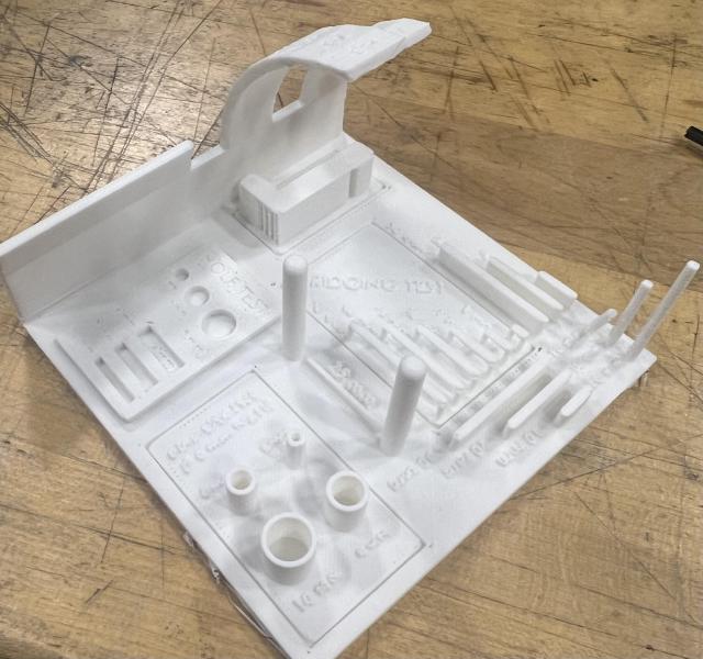
The printers would print this test print, which gives a lot of tiny details. An interesting test is the overhang test. I was surprised at how far it could go without falling (apparently slicer improvements have led to lots of improvements here. And there’s a fresh new trick with drawing arcs so things don’t fall). I probably should have taken a closer look underneath. There was also the bridging test. Again, it makes an impressive distance. Overall, I think because I’m so new to 3D printing, I wasn’t sure what to look for and was just like, wow, it seems to pass all of the tests when I probably should have looked closer. I could have also used a test to figure out clearance for my hinges, but ah, maybe next time.