Electronics Design 🔗
We’re designing development boards this week. For my final project, I know I want to use one of the ESP32 boards and something like I2C to communicate with an RFID reader, and then have some other outputs for LEDs and what-not.
I had grabbed a few RFID chips online for testing and maybe for the final project too. I found this data sheet. In case these chips don’t work at all, it seems like this is still a good bet. Based on this, it needs 3.3V.
So I think I’ll have one side be I2C. This previous project did something similar, so I don’t feel like I’m completely off. It looks like I2C needs SDA, SCL, and 3.3V and ground. Interestingly, they include both a 5V and a 3V3 pin. That seems reasonable enough. As for the other things connected, I’m going start by assuming I’ll connect some addressable LEDs, which usually require 5V, a data pin, and ground. Hopefully whatever else I connect will be along the same lines.
So now it’s time for laying it out! I ended up going with KiCAD, though SVG-PCB is very cool and I read its paper. I was also planning on making stylish paths (arcs?) but it turned out tricky enough to place them with the regular 135 degree angles. Maybe if I have time later or am making something more flexible than the development board, I’ll come back!
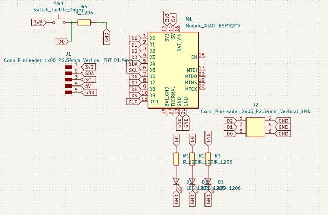
I start by including the library of what things we have in the labs. In the schematic, I put down the Xiao, and hooked up the 5-pins for IIC. I don’t know what I’m doing. I stick close to the fabxiao example. Then I realize I can use labels to clean things up, so I delete everything and start again. And then I end up deleting everything and starting a third time, and this time I’m starting to understand things.

D0, D1, and D2 are both digital Analog, so I’ll expose those. It would be nice to include the other communication protocols (UART and SPI) in case I choose a different RFID reader or want to use an e-ink display or something. But I’m not sure how to put the pins nicely on the board, so I give up on that idea stick with a few things, which should be enough for my initial tests. A button seems like a good idea to trigger syncing. I also figure I like LEDs, so I dropped in three of those (looking back, I probably could have put another header pins here, but ah well).
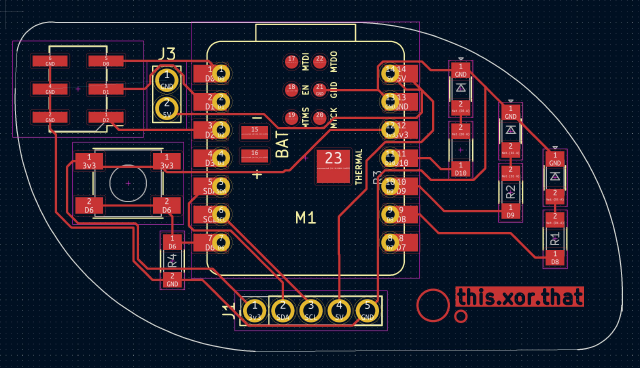
I switch to the PCB editor. After some trial-and-error (and surprised when a misplaced resistor turn all my GNDs into D6), I ended up with this funny bean-shaped schematic, and I successfully avoid jumper resistors. There are a bunch things I’m not sure about, like whether this will be totally inconveninent, or whether the labels will show up, and it was hard to align the bean’s edges quite right.

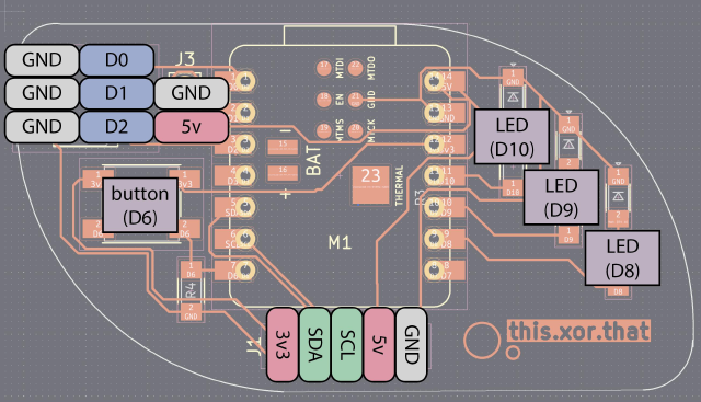
The button is on D6. LEDs are on D8, D9, D10. 3 pins on the right are D0, D1, D2 (with ground). IIC is on the lower 5 pins. Here’s the pin outdiagram for the board that I made in Illustrator, along with the LED/Buttons.

Eager to get one or two fo these milled so I can test out the RFID reader and ESPC3 networks.
group assignment: 🔗
 use the test equipment in your lab to observe the operation
    of a microcontroller circuit board
Quentin showed us how to debug electronics. The multimeter can measure many things. It can measure voltage by sending a little tiny bit of current. That’s useful to test if thigns are connected that you expect to be. We watched starting with 5V and then the step that brought it down to 3.3V.
Some notes:
- If you don’t connect to ground, voltage means nothing.
- Something that says “5V” is 5V “within some range”, so don’t panic if the multimeter says 5.1 or something
- Sometimes two pins are the same.
- Don’t leave the multimeter in amplimeter mode, or it can ruin some else’s project.
- You can accidentally ask for infinite amount of current. But things like USB drives will protect you from burning it out.
Also saw a cute little oscilloscope that was just a little block, Salea. Quentin showed us that the SAMD has an analog output ADC that can fake a sine wave with little tiny pulses.