This week, we milled the boards we designed last week.
I started by loading my board into the mods script for the Carvera mill. Andd, very quickly realized I had not set my design rules correctly. I had used the numbers from the design rules link, but that didn’t match the machine I was using, and the preview clearly showed that many of my traces would be shorted.
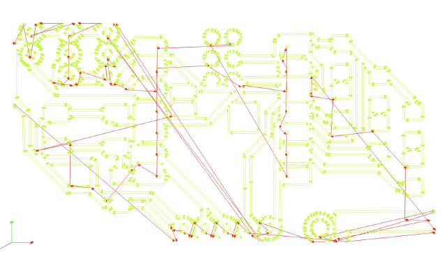
So back to KiCad. I updated the design rules, and rearranged the board. I also decided I did want SPI support, so I exposed those pins. Running through the mods workflow, I also realized I just needed a black and white image (I had taken the SVG from KiCAD and converted it to a png with 1000dpi.) I didn’t have much fun drawing my curves in KiCAD, so I tried drawing the board outline in Illustrator and then pulling it into KiCAD instead. This was a lot easier to create the shape I wanted. (KiCAD and Illustrator had disagreements about scale, so I had to rescale it by 1.3333. I’ve seen this before when laser cutting something on Illustrator I had created in Inkscape, where one uses 72dpi and the other uses 96dpi.)
Given that I was in Illustrator, I could also update the board to use curved lines like I wanted. While spending a lot of medatative time doing that (I also made the power and ground lines a little thicker), I schemed about trying to automate this (I thought about sticking things to a grid to simplify things, or just giving a drawing tool that used curves instead of the little 45 degree turns. I also read up a bit on how auto-routing worked, which has some nice tricks.)
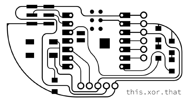
If I forgot to invert, I’d get another bad cutout.
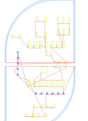
Along with inverting, I needed to manually make a filled area in the cut layer that I wanted to exclude.
I also needed to cut through to use my header pins. It was also extra important to “export including art board” so the edges and the traces would line up! I also rotated the board, so I could get the tabs for free (to hold the board). But by inverting the input, and using a cutout like this:

And the cut plan looked like this:
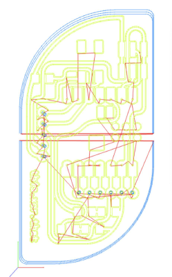
Beautiful!
Milling 🔗
After being away for the long weekend, I was back Tuesday night to start milling. I screwed down a piece of copper on top of a sacrificial piece, and held it down with a bit of double-sided tape. But it seemed like that wasn’t quite enough to hold it down.
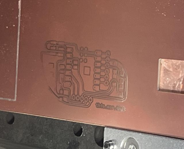
At first I thought it was just a few traces that would need to be cut out, and I wasn’t sure if I’d need to mill the whole board. Then I saw other folks’ boards and realized that the “cut out” area was supposed to be yellow instead of the polished copper I was seeing. That was okay, I could use this board to double-check the header pins could fit, and I also realized the cuts for the header pins weren’t aligned either (I think I wasn’t exporting the artboards in Illustrator, so it was cropping funny.)
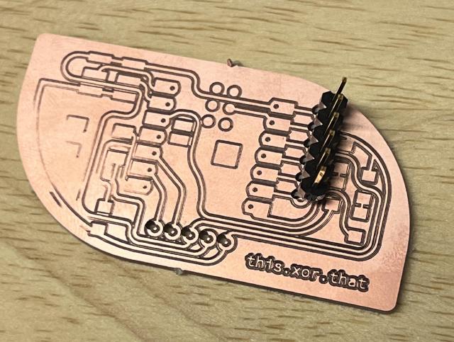
So I fixed those things and milled a second board. This time, I put more double-sided tape down, pushed the board firmly into the tape, and cut it closer to a side that would have the clamp. The tape worked good, maybe too good. I cracked the plastic layer of the board a bit removing the remaining copper. Quentin stopped by, and helped me pry the piece off the sacrificial piece with a chisel. He also grabbed me the right kind of header pins because I was testing with the horizontal pins when I wanted vertical ones.
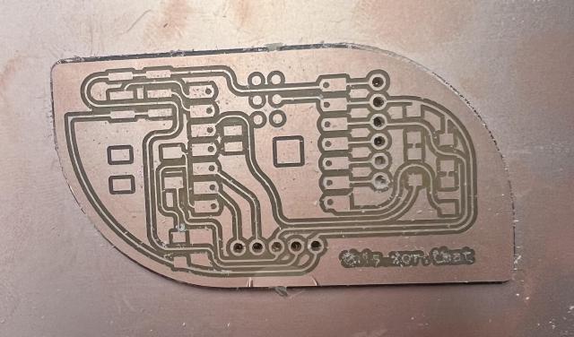
Here’s a different angle on the crack. The trace still worked though when I tested it with the multimeter..
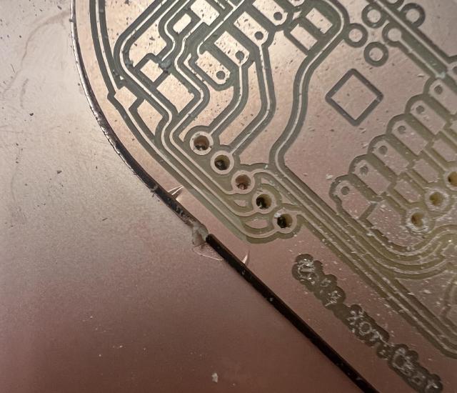
I also looked at the board through the microscope, though I couldn’t get a good photo. There was one place it had missed milling that I needed to cut.
Soldering 🔗
So I’ve soldered a couple of times, but I am no expert. That said, having the proper set-up (thin solder wire! hot solder iron! magnifying glass and lights!) did make a big difference compared to my previous soldering experiences.
I tacked down the Xiao, and soldered the other pins.
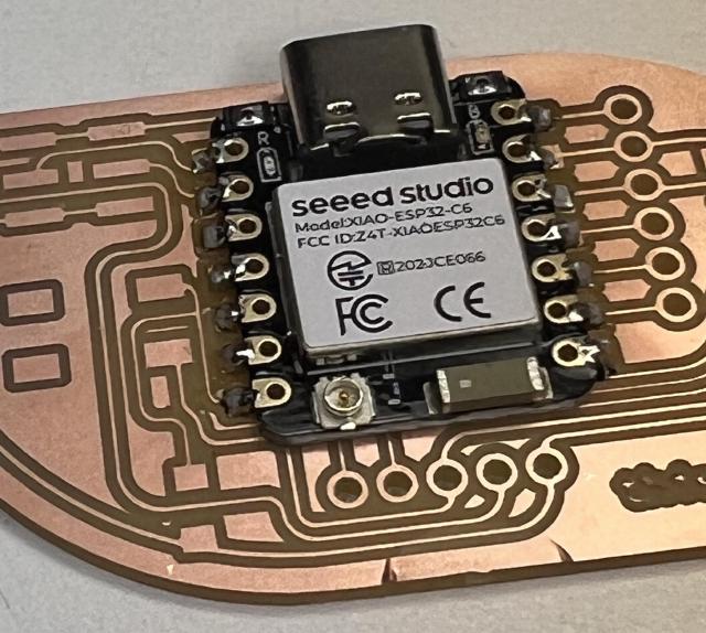
The header pins weren’t that fun to do. I tinned the rings and the pins (pins heated up on one side make them loose in their plastic, AND can burn you on the other side, I learned). After trying to set them in on top, I ended up soldering them through the back. That made the slot very easy to access.
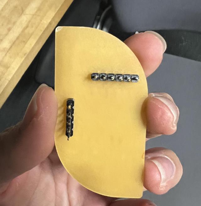
Well, and here’s the grand reveal. It looks like a murder scene, just in time for Halloween!
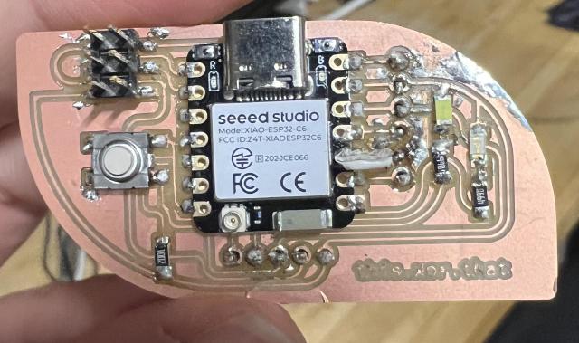
This turned into a bit of a mess: I ended up screwing up one of the pin contacts, like the copper was no longer visible? I soldered a wire to connect the pin to the Xiao. I also have no clue if I soldered the LEDs on in the right direction.
Testing 🔗
I went down two routes, trying to run Rust on the chip and just trying to get the chip working using the Arduino IDE.
Rust 🔗
There’s a nice page here that walks through running Rust on ESP chips. It seems like it would be used in place of the Arduino IDE for flashing as well.
I’m planning to use no_std since that’s closer to the metal and my code from week 3 was based on it, so I follow instructions for no_std and the C6 chip that I have.
rustup toolchain install stable --component rust-src
rustup target add riscv32imac-unknown-none-elf
There are instructions for a basic job using a template, so I install cargo-generate and cargo-espflash. The latter gives me a bit of trouble with compilation failing due to type annotations, but by using cargo install cargo-espflash --locked as suggested here allowed me to compile.
The next step is run cargo, but this fails with
**error****:** could not execute process `espflash flash --monitor target/riscv32imac-unknown-none-elf/debug/hello-dev-board` (never executed)
I can successfully check the board info
➜  hello-dev-board git:(main) ✗ cargo espflash board-info
[2024-10-16T15:40:36Z INFO ] Detected 2 serial ports
[2024-10-16T15:40:36Z INFO ] Ports which match a known common dev board are highlighted
[2024-10-16T15:40:36Z INFO ] Please select a port
✔ Remember this serial port for future use? · no
[2024-10-16T15:40:45Z INFO ] Serial port: '/dev/cu.usbmodem2101'
[2024-10-16T15:40:45Z INFO ] Connecting...
[2024-10-16T15:40:46Z INFO ] Using flash stub
Chip type:         esp32c6 (revision v0.1)
Crystal frequency: 40 MHz
Flash size:        4MB
Features:          WiFi 6, BT 5
MAC address:       54:32:04:21:5f:18
I try running the espflash command directly without the --monitor part, and it looked like it was successful, but since I wasn’t monitoring I could see any serial output, and instead the LED just stopped flashing.
Chip type:         esp32c6 (revision v0.1)
Crystal frequency: 40 MHz
Flash size:        4MB
Features:          WiFi 6, BT 5
MAC address:       54:32:04:21:5f:18
App/part. size:    31,040/4,128,768 bytes, 0.75%
[00:00:00] [========================================]      13/13      0x0                                   [00:00:00] [========================================]       1/1       0x8000                                [00:00:00] [========================================]      18/18      0x10000                               [2024-10-16T15:44:25Z INFO ] Flashing has completed!
Arduino IDE 🔗
I realize I have this page open, so I start following those steps instead.
I install the boards, select the ESP32-C6, and run the Blink test. And the board is blinking again! Yay.
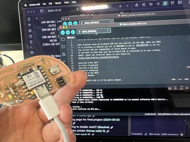
Next I try updating to the first LED. It also lights up! wow, I soldered it in the right direction.
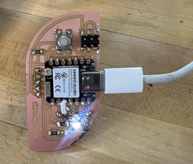
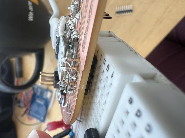
From there on, things went less well. The second LED didn’t light up (probably backwards), the button didn’t seem to send data (I was suspicious when I realized I probably had connected the wrong pair of pins..), the 6 pins meant for LEDs are too close together to fit the clip I have, and when I put the header pins in a broad board (awkawrdly) to try to test those pins, it pushed the metal through the plastic and stretched the copper off the board! At this point, I am thinking of redesigning and reprinting the board (no more through-header pins) before continuing testing with it.
Group Assignment 🔗
During training, Quentin talked through creating the gerber boards to send to PCB places. You usually print two sides, even if you only have one because it’s standard. You can print the silk screen too. There are options for types of pads, like tin or gold so the copper won’t oxidize. Try to use lead-free. If you order a stencil, you probably want a frame too. Can also order a panel of boards, along with a stencil in a panel so you can produce more at once.
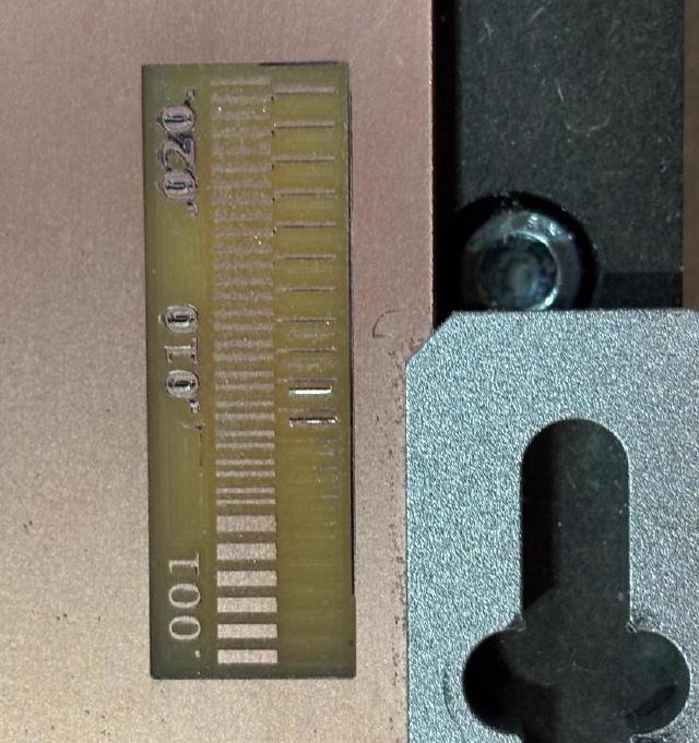
Brian and folks milled the design rule board for us.
