Luckily I had fixed my development board from Week 6 last week, so at the minimum, I just had to design a board for a sensor and plug it in. I was interested in the hall effect because I heard you could use it to identify things by flipping magnets different ways (either Quentin and/or someone else from the class had done it). I was also interested in how it meant that the device you moved didn’t have to have any electronics in it. After seeing Nina’s embedding of sensor things into molding, I wanted to also revisit Week 7 with a fancier mold now that the chaos of the true week was over.
Creating a circuit board 🔗
After class on Wednesday, I checked what sensors were available in the electronics lab. They had two Hall effect. I opted for the fancier one with xyz data since I didn’t have something in particular in mind, I could try to use it and learn how to use the simpler one too.
I looked at Neil’s example board, which had a micro controller. I wanted to use my dev board though. After some flailing, I found the answer datasheet, which told me what resistors and capacitors to use.
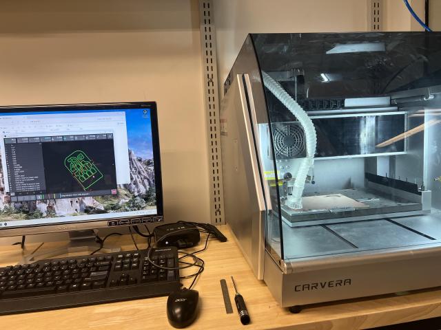
I designed a board and milled it, and then soldered the pieces together.
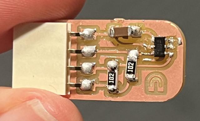
Cute! Then I spent a long time trying to debug the board and realized I had missed a wire.
- I started with Neil’s script that initalized the board and communicated over the wire. I wasn’t getting any result.
- I tried using an RFID reader I had, but realized that was SPI and not I2C.
- I used the script to iterate over all I2C ports to try to find the device. It wasn’t picking it up.
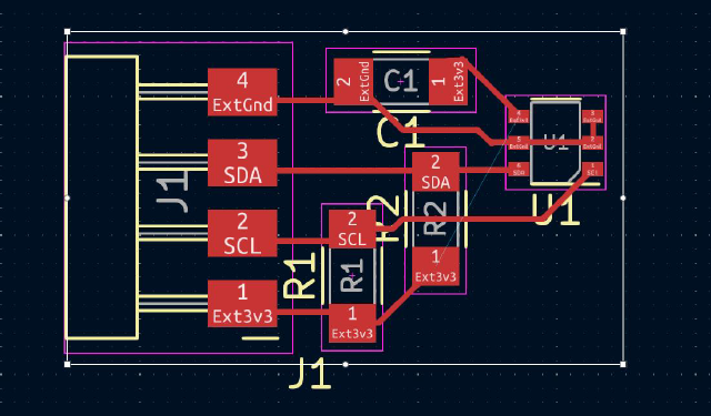
- I took another look at the board design.. and realized I had forgotton to connect the power pin to the chip. There was a little unconnected wire in the diagram.
- If there’s a error loading the code on the board, hold down boot/reset, and hold down boot while it’s loading.
I soldered another wire on the board to add in the missing lead. And the I2C discovery script ran!
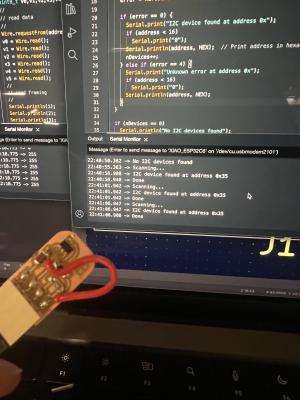
I outputted the data to the wire, but it was only 0xFF. I went back to Neil’s script, which had some initailization communication with the chip. And then I started getting data!
I changed the data to comma-delimited of the 6 bytes the script read, which meant the Serial Plotter would plot something.
I moved a magnet around, and saw it changing! But then I struggled for a bit to understand what I was seeing.
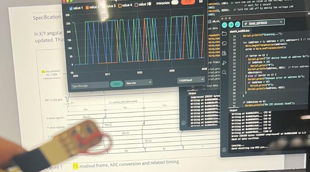
Understanding the data 🔗
The number would increase and decrease in response to the magnet moving but in weird ways. Value 4 was oddly stable around 74. I wondered if it was temperature (incorrectly just because it was around room temperature in fahrenheit), and noticed when i held my finger on the chip it would change. It turned out it was temperature, which is interesting, but I guess it’s so you can correct for how the magnetic field changes in extreme temperatures.
Back to the datasheet. It said the data was 12-bit, with the most-significant bits for x, y, z, and temperature in the first 4 numbers, but in twos-complements, so the first bit represented negative values. The least-significant bits were split across the 5th and 6th byte.
At this point, I also looked through the previous work, and saw most people usign the hall effect sensors used a library. I took a look at that code, and saw things were starting to line up with what I had read. So I had gotten this far in understanding the spec, I thought I should finish the job and brush off bit math.
Then I pulled in the last bit of math from the datasheet that said how to translate the data into actual units, mT and celsius.
   int raw_bx = -2048 * (v0 >> 7) + ((v0 & 0x7F) << 4) + (v4 & ~0xF0);
   int raw_by = -2048 * (v1 >> 7) + ((v1 & 0x7F) << 4) + (v4 >> 4);
   int raw_bz = -2048 * (v2 >> 7) + ((v2 & 0x7F) << 4) + (v5 & ~0xF0);
   int raw_bt = -2048 * (v3 >> 7) + ((v3 & 0x7F) << 4) + (v5 >> 4);

   float bx = raw_bx * 0.13;
   float by = raw_by * 0.13;
   float bz = raw_bz * 0.13;
   float bt = (raw_bt - 1180) * 0.24 + 25;
Doing things with the data 🔗
I want to try using this as a controller for live visuals. I started with the magnet in a piece of clay, and covered with tape so it would be less sticky. I used a short script in Python (written with the help of ChatGPT) to monitor the comma-delimited serial output, average the number, and send it to my other script as OSC.
import serial
import time
import numpy as np

serial_port = "/dev/cu.usbmodem101"
baud_rate = 115200

with serial.Serial(serial_port, baud_rate, timeout=1) as ser:
    start_time = time.time()
    print("Reading data...")

    vals = np.zeros((5, 20))

    try:
        while True:
            for i in range(20):
                line = ser.readline().decode("utf-8").strip()
                if line:
                    result = line.split(",")
                    if len(result) == 4:
                        (x, y, z, t) = result
                        vals[0][i] = x
                        vals[1][i] = y
                        vals[2][i] = z
                        vals[3][i] = t
                        vals[4][i] = time.time() - start_time

            r = vals.mean(axis=1)
            assert r.shape == (5,), r.shape

            send_message(r[0], r[1], r[2])

    except KeyboardInterrupt:
        print("Stopped by user.")
Cooler shape 🔗
I’ve been enjoying revisiting the previous week’s assignment the week after. This time I wanted to make a two-part mold around a crystal shape.
I started by creating the crystal. I figured out how to create an API in Fusion 360 to give me sliders to control specific parameters. Basically it’s creating two planes, which are then cut along the P32 (you rotate 3 times, and then mirror it on the other side.)
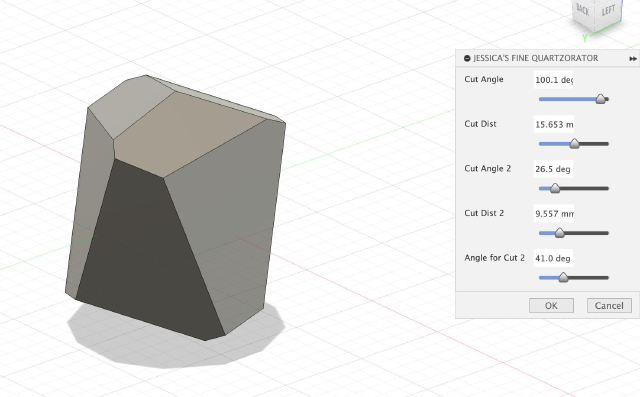
(You go to Utilities -> Add Ins -> Scripts and Add Ins, then Edit a script (or create a copy of one). The important parts are commands/__init__.py variable commands. Then editing the corresponding entry.py)
With that I could find a crystal I liked.
It was a little tricky to figure out what would be a good way to cut the crystal. I went along the edges of the facets, but figuring out what direction the line shoudl come out of that. It worked out if I drew a diagonal to the corresponding shape on the other side, and extended the line as far as I needed to. Maybe it didn’t matter too much, because in the end I just needed something that wasn’t too close to the edge on either side, and then I just created the mold for one side, and then the other.
My first mold, I thought I had figured out crystals and thought I could just rotate it 180 degrees to get the other mold. I now think I was close, but I just needed to mirror the second mold.
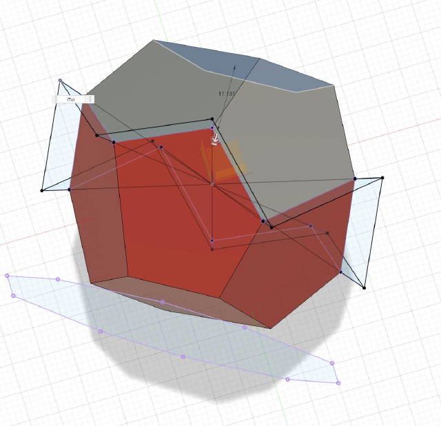
Then I 3D printed it and casted the mold in silicone. Then I cut out pour and air holes. I used some wire to suspend a magnet through one of the air holes, and then poured in the Hydrocal.
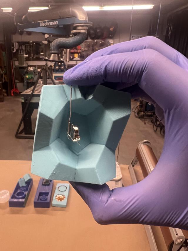
The first batch was too thick, either I waited too long, or was too close to the 100-40 ratio instead of 100-45 ratio.
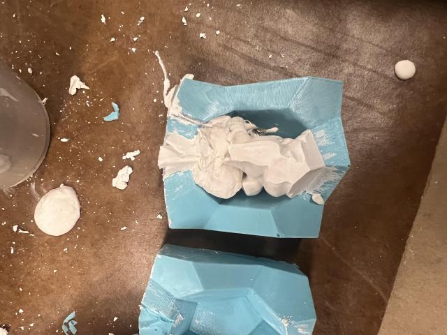
I freed the magnet and tried again. This time, I went with an extreme 100-50 ratio, and worked right away. This time it was very fluid and I had no problem filling the part. After it was dry, I started trying to make sense of the data. I tried rotating the magnet at different angles. I also made a little stand that has a dish that points to the most sensitive part of magnetometer.
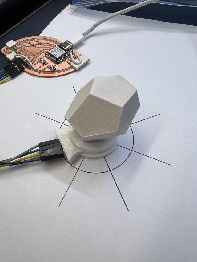
But that didn’t really have much rhyme or reason. I think either I should try the two magnetometers to triangulate, or play more with the “moving it away from the center point.” In any case, it’s a cool little device.
Group Assignment 🔗
We met with Erik in the CBA electronics room. Erik shared a device which used two magnetometers and a neural network to locate a magnet. He connected it with the normal oscilloscope. It was important to figure out the right scale in order to start to notice the data being sent. There is also a trick for very fast signals where it (samples? overlays?) a part of the signal.
I had my much less sophesticated magnometer that was a little easier to probe, so we also took a look at that. Using the oscilliscope we could see a bit of data. We used the digital analyzer to try to read in teh bits, which were all 255 (i think because we hadn’t set the initialization code?)
   group assignment:
      probe an input device's analog levels and digital signals
   individual assignment:
      measure something: add a sensor to a microcontroller board
      that you have designed and read it