The thing that caught my eye from the list of output devices was Charlieplexing, a trick which allows you to use N pins to control N(N-1) lights. The small number of pins also meant that I could use a smaller ATTinys as well.
I’ve also been playing with the board designs. I’ve been laying out the board in KiCAD, and then bringing it into Illustrator.
I started with re-drawing one of the diagrams from Wikipedia to try to wrap my head around the layout. Then I sketched a bunch of ideas to try to turn it into something else. It turned into a tree made out of tangent arcs (like how wrought iron gates look, or persian carpet patterns, or…).
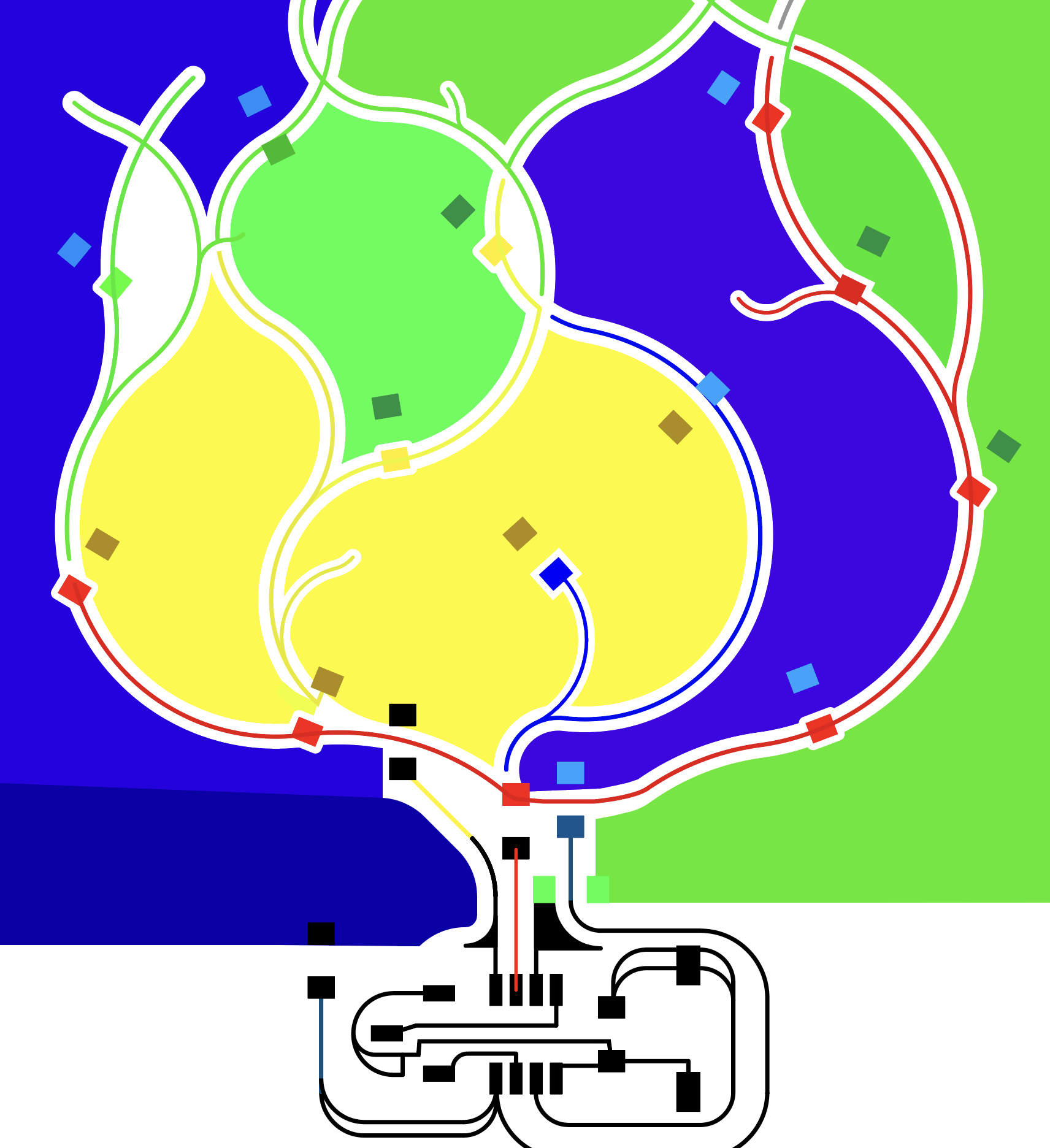
Turning this into a Charlieplex circuit board turned out to be a straightforward puzzle: you need color a plane with four colors so that you can connect two LEDs in the opposite orientation between every pair of colors. Through some trial and error, I came up with this layout:

So one thing I wanted to do was to take advantage of the negative space as well, since PCB milling leaves big pieces of copper. There’s also the trick of using the resistors needed for the LEDs to hop over a lead. Also by having the branches cross each other, I could sneak connections between the different regions.
I wondered between using one of my generative SVGs or to draw one out. I ended up with a funny compromise: I sketched a shape by hand, and then used OBS to overlay my drawing program on top of it, and trace out the curve.
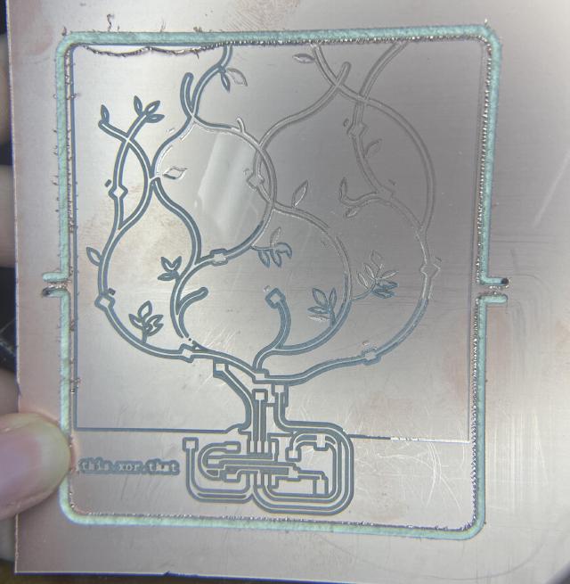
Milling 🔗
The stock is still warped, and this board is a little large so that even if I clamped the edges, the middle wouldn’t cut through. (I should try flipping the stock over when it acts up..)
I inquired to my parents what kind of tree I was drawing, and they said it was an Elm and that I should have more leaves on it. Unfortunately, that one didn’t mill all the way through, so I stuck with the original design.

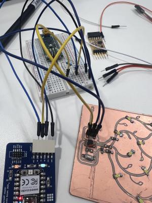
Since I was using the ATTiny412, I had an excuse to make the all-in-one programmer. I had also chosen to expose only 3 pins (VCC, UPDI, GND), so I needed a UART to UPDI, which puts a 4.7k resistor between RX and TX. This one turned out a bit annoying, with the first one soldering really badly, so that the two pin horizontal kept bending and eventually ripped off, and then when I went to mill it again, I had problems with the mill not going deep enough. I ended up just using a breadboard.
Programming 🔗
The first challenge was installing megaTinyCore, which has expired certs so Arduino won’t let you download the boards. During class, Quentin had offered to host it, but I couldn’t find the URL, so instead I copied the file locally and used file:// to point to the file. This worked, and I downloaded megaTinyCore.
Now I ran into problems. It would say pymcuprog.pymcuprog - ERROR - Operation failed with PymcuprogSerialUpdiError: UPDI initialisation failed.

I went to office hours and got a lot of help from Quentin. As an abridged summary:
- Quentin recommended a capacitor across VCC+GND on the ATTiny. I put a 100nF one on, though in the future I should use a 1uF one.
- We compared a board he knew worked, and realized the programmer wasn’t working on that. He inspected the board and notice I had used a too big of resistor size on the programmer.
- With that, we were able to program his board with my programmer, so we knew I had a working programmer.
- Folks from fabacademy had posted about needing to use pymcuprog directly because something about calling it from Arduino meant no data was comign through the ports. Now I started to get the error
pymcuprog.pymcuprog_main - ERROR - Error with st. It then would give aUPDI initialisation faileduntil I unplugged and plugged it back in. - We tried a lot of things: We went back to using pyupdi, which gave a little more info. We tried baud rates, in pymcuprog, pyupdi, and the modified pymcuprog used by megaTinyCore. We tried using different versions of different libraries by running the command that Arduino runs (so in the same environment, and also with another python environment.)
- (
UPDI initialisationalso fails if I plug the wires in wrong, so check that first.)
Quentin recorded what my computer was sending vs what his computer sent. With that I opted to program it on a Windows computer.
Actually programming 🔗
I was a little confused by the pinout, and ended up needing to do some trial and error until I found it was 0, 1, 2, 3 that I wanted. I’m not sure why it’s like that!
For Charlieplexing, you use both high and low outputs, as well as inputs. You basically set everything to INPUT, except for the corresponding two wires, and you set one to high and one to low to decide which of the two diodes to use.
const int pins[] = {0, 1, 2, 3};

void setup() {
    off();
}

void setLED(int high, int low) {
  off();

  pinMode(high, OUTPUT);
  digitalWrite(high, HIGH);

  pinMode(low, OUTPUT);
  digitalWrite(low, LOW);
}

void off() {
  for (int i = 0; i < 4; i++) {
    pinMode(pins[i], INPUT);
  }
}

void loop() {
  for (int i = 0; i < 4; i++) {
    for (int j = 0; j < 4; j++) {
      setLED(pins[i], pins[j]);
      delay(500);
    }
  }
}
Running it from a Windows machine, and a special collection of LEDs started glowing that was not the expected “one-at-a-time”. I had noticed this earlier when I was testing the board with the multimeter.
Given that, the lights did not glow in the right order. I needed to go in and debug the board a bit more. It was kind of a fun puzzle because you could see which LEDs would glow together. I had one LED flipped the wrong direction, so that was an easy fix. I still had a problem where the Blue-Green ones would not light up, and I noticed there was 100ohms between them instead of the expected infinite resistance. I
I thought that maybe my trick of splitting the “blue” region between two areas was too clever, so I put a jumper wire in between instead. Then I realized the Blue and Green regions were shorting together that was solved by cutting along the bottom right.
And with that, the board worked! (with a bonus delay in there because I am also setting the input-output to the same values (e.g. Blue-Blue)).
Group assignment 🔗
Erik showed us using the voltage regulator. He fixed the voltage to 6V to match the 2AA that normally charge a robot. We saw the ~60 mA being drawn by the ESP32. Then he had the robot walk, and it jumped up to 500 mA, and when he blocked the robot, it even would jump up to an amp.
We also talked about sensors: the sensors tend to not take very much energy, especially the ones provided in the lab. Apparently if you want super precise sensors, you start to need a ton of energy, like in HiFi speakers or scientific measurement.
   group assignment:
      measure the power consumption of an output device
   individual assignment:
      add an output device to a microcontroller board you've designed,
         and program it to do something