Week 12 Networking
Programming a blueooth joystick
✅ individual assignment: design, build, and connect wired or wireless node(s) with network or bus addresses and local input &/or output device(s)
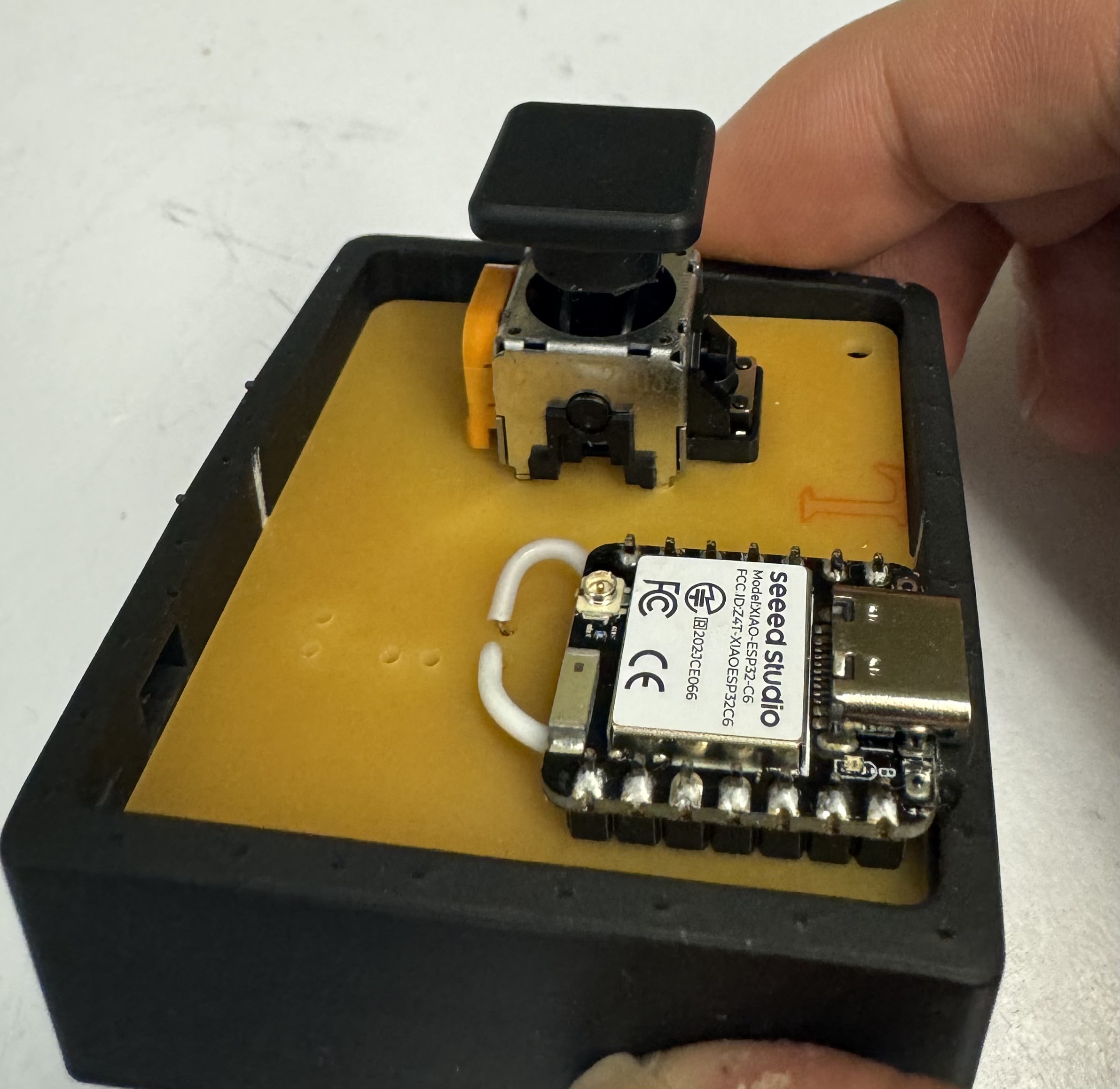
I made a joystick with Marcello in week 8 and now trying program it with bluetooth functions.

								/*
  Blink

  Turns an LED on for one second, then off for one second, repeatedly.

  Most Arduinos have an on-board LED you can control. On the UNO, MEGA and ZERO
  it is attached to digital pin 13, on MKR1000 on pin 6. LED_BUILTIN is set to
  the correct LED pin independent of which board is used.
  If you want to know what pin the on-board LED is connected to on your Arduino
  model, check the Technical Specs of your board at:
  https://www.arduino.cc/en/Main/Products

  https://www.arduino.cc/en/Tutorial/BuiltInExamples/Blink
*/

// input pins
const byte Xin = A1; // X input connected to A0
const byte Yin = A2; // Y input connected to A1
const int Buttonin = 0; // pushbuttom input connected to Digital pin 7

// input pins
const byte ledPower = D4; // select the pin for the blue LED PB0
const byte ledConnection = D5; // select the pin for the blue LED PB0
const byte led = D6; // select the pin for the blue LED PB0

//threshold because of physical limitation 1700 centre of joystick at x axis
const int THRESHOLD_LOW_X   = 1600;
const int THRESHOLD_HIGH_X  = 1800;

//threshold because of physical limitation 1600 centre of joystick at y axis
const int THRESHOLD_LOW_Y   = 1500;
const int THRESHOLD_HIGH_Y  = 1700;

// joystick value
int sensorValuex,sensorValuey, buttonState;

// state machine
int state       = 0;

// the setup function runs once when you press reset or power the board
void setup() {
  // initialize digital pin LED_BUILTIN as an output.
  Serial.begin(115200);          // initialize serial communication


  pinMode(LED_BUILTIN, OUTPUT);
  pinMode(ledPower, OUTPUT);
  pinMode(ledConnection, OUTPUT);
  pinMode(led, OUTPUT);

  pinMode(Xin, INPUT);
  pinMode(Yin, INPUT);
  pinMode(Buttonin, INPUT_PULLDOWN);


  digitalWrite(ledPower, HIGH);  // turn the LED on (HIGH is the voltage level)
  digitalWrite(ledConnection, HIGH);  // turn the LED on (HIGH is the voltage level)
  digitalWrite(led, HIGH);  // turn the LED on (HIGH is the voltage level)
}

// the loop function runs over and over again forever
void loop() {
  moveAxis();
}

void readPotentiometer(){
  sensorValuex  = analogRead(Xin);
  sensorValuey  = analogRead(Yin);
  buttonState   = digitalRead(Buttonin);


  Serial.print("  Axis XY");
  Serial.print("  X:");
  Serial.print(sensorValuex);
  Serial.print("  Y:");
  Serial.println(sensorValuey);
  Serial.print("  button:");
  Serial.println(buttonState);

}

void moveAxis(){


  if(state == 0){
    readPotentiometer();
    if(sensorValuex > THRESHOLD_HIGH_X){ //move right
      state = 1;
    }else if(sensorValuex < THRESHOLD_LOW_X){ //move left
      state = 2;
    }else if(sensorValuey > THRESHOLD_HIGH_Y){ //move down
      state = 3;
    }else if(sensorValuey < THRESHOLD_LOW_Y){ //move up
      state = 4;
    }
  }else if(state ==1){
    Serial.println("MOVE RIGHT");
    readPotentiometer();
    if((sensorValuex < THRESHOLD_HIGH_X)&& (sensorValuex > THRESHOLD_LOW_X)){
          state = 0;                  // joy stick at the centre back to state 0
    }

  }else if(state ==2){
    Serial.println("MOVE LEFT");
    readPotentiometer();
    if((sensorValuex < THRESHOLD_HIGH_X)&& (sensorValuex > THRESHOLD_LOW_X)){
          state = 0;                  // joy stick at the centre back to state 0
    }

  }else if(state ==3){
    Serial.println("MOVE UP");
    readPotentiometer();
    if((sensorValuey < THRESHOLD_HIGH_Y)&& (sensorValuey > THRESHOLD_LOW_Y)){
          state = 0;                  // joy stick at the centre back to state 0
    }

  }else if(state ==4){
    Serial.println("MOVE DOWN");
    readPotentiometer();
    if((sensorValuey < THRESHOLD_HIGH_Y)&& (sensorValuey > THRESHOLD_LOW_Y)){
          state = 0;                  // joy stick at the centre back to state 0
    }

  }

}
How to Set Up an SSR Server
For the friends that are visiting China in January.
ShadowsocksR is a commonly used protocal used to obfuscate the network firewall (kind of like VPN but better).
The working principle is to mask the HTTP request as a different website and the data packages are encrypted.
This is just a tutorial for networking skills, please refrain your online activities in accordence with local laws.
Follow the steps below to set up your own ShadowsocksR (SSR) server:
1. Preparations
- Purchase a VPS (Virtual Private Server). Recommended providers: Tencent Cloud, Alibaba Cloud, Google Cloud, AWS...
- Install a Linux operating system. Recommended: Ubuntu or Debian.
- Configure the server environment, including SSH login and firewall settings.
2. Install Shadowsocks
Run the following commands to install Shadowsocks:
apt-get update
apt-get install python-pip
pip install shadowsocks
Create a configuration file at /etc/shadowsocks.json with the following content:
{
    "server": "0.0.0.0",
    "server_port": 8388,
    "local_address": "127.0.0.1",
    "local_port": 1080,
    "password": "your_password",
    "timeout": 300,
    "method": "aes-256-cfb"
}
Start the Shadowsocks service:
ssserver -c /etc/shadowsocks.json -d start3. Install ShadowsocksR
Run the following commands to install ShadowsocksR:
apt-get install python-pip
pip install git+https://github.com/shadowsocksr-backup/shadowsocksr.git@master
Create a configuration file at /etc/shadowsocksr.json with the following content:
{
    "server": "0.0.0.0",
    "server_port": 8388,
    "local_address": "127.0.0.1",
    "local_port": 1080,
    "password": "your_password",
    "timeout": 300,
    "method": "aes-256-cfb",
    "protocol": "auth_aes128_md5",
    "protocol_param": "",
    "obfs": "tls1.2_ticket_auth",
    "obfs_param": ""
}
Start the ShadowsocksR service:
ssr -c /etc/shadowsocksr.json -d start4. Configure the Firewall
Run the following command to open port 8388:
ufw allow 8388/tcpEnable the firewall:
ufw enable5. Test the SSR Server
Use a Shadowsocks client to connect to your SSR server and test the basic network connection.
6. Configure Automatic Startup
Run the following command to configure the ShadowsocksR service to start automatically:
systemctl enable ssrWith this setup complete, your SSR server is ready to run and can be connected via any compatible client.