FINALFINALFINALFINALFINALFINALFINALFINALFINALFINALFINALFINALFINALFINAL


"Any sufficiently developed technology is indistinguishable from magic"

Arthur C. Clarke's Third Law


LEVITATE! LEVITATE! LEVITATE!


There is an aspirational quality to wanting to make /almost/ anything, perhaps even fantastical. I want to lean into fantasy; to render the sensorial potential we have with what we make as magical.
For a final project, I would like to create a levitating, interactive crystal ball. The ball might act as an interactive display, a touch-free controller, or a climatic visualizer. Whatever it is, it must feel magical.
As a base idea, I envision developing a maglev system that can levitate the ball, and a series of programmable LED's that can animate the surface of the ball. The ball should be sensitive to proximity of a user, and respond
in some way before touch is made.


VISUAL RERERENCE:


GRASSHOPPER SKETCH:


/TRACKING 10.25.24/ HOW TO SUCCESSFULY MAKE A SPHERE THROUGH A SPIRAL:


> make a hand change an LED
> make something float
> make a hand change a static image mapped onto LEDs
> make a hand change a moving image mapped onto LEDs
> make a static or moving LED ring float
> make several static or moving LED rings (i.e a sphere) float
> make a hand change a floating sphere
> make a hand change a floating sphere that is rotating

> Sell Out


Thinking about a system diagram, I envision the project existing with two integrated systems: The MagLev Base and the Interactive Sphere. The MagLev base will float (and possibly also rotate) the sphere, and the Sphere should be able to read both user behavior and information passed from a digital display. One big question i have is how to address the LED's relative to the digital display if the LEDs are rotating, and thus always changing position, especially if the digital display is also moving. Roughly im thinking it might be possible to create an invisible Voxel matrix and use that absolute position to map the LEDs relative to where they are at any given time. Would be a nice study.


/TRACKING 11.08.24/ SYSTEM SKETCH:

/TRACKING 12.11.24/ MODEL


    As production began, I made a comprehensive model of all the components to be fabricated and assembled:

    > The Outer Shell (3D Printed Transluscent PLA)
    > (15) WS2812B IP30 RGB LED Strips
    > (15) Rings for LED Strip Support (3D Printed PLA)
    > (5) Vertical LED Supports (3D Printed PLA)
    > (1) Interior Structural and Electronics Core (3D Printed PLA)
    > (1) Microcontroller to power LEDs
    > (1) 7.4V 2000 mAh 8C Battery
    > (1) Buck Converter to step 7.4V down to 5V for LEDs
    > (1) Base Magnet
    > (1) Plywood Base (CNC Plywood, Walnut Stain)
    > (1) Analog Maglev board with a ring magnet, 4 electromagnets and Hall effect sensors
    > (1) Maglev Housing (3D Printed PLA)

Two of the biggest design considerations revolved (no spherical pun intended) around the power budget for the sphere, since the floating effect necessitated a wireless device, but having 550 LEDs required a considerable current supply. Initially I hoped to power the sphere on a couple of AA batteries and have the Interior core be smaller than it eventually became, but my power budget came out to a 5V 12A limit, so I had to source a heavy duty battery. The One i'm using is the kind used to power RC Cars and airplanes. The second big consideration was the magnetic system. The base magnet is the primary structural logic, at a max of 5cm, and so the entire sphere is actually designed around the ability to hook up to the magnet with the detail I developed below:

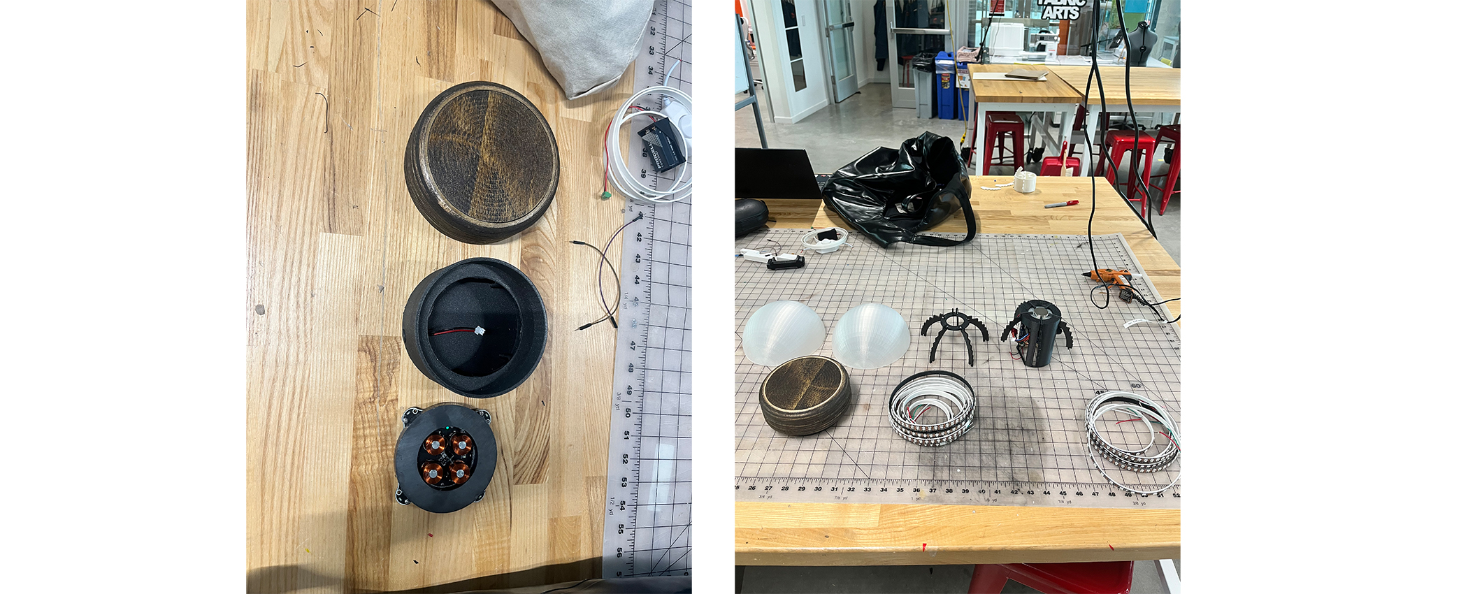
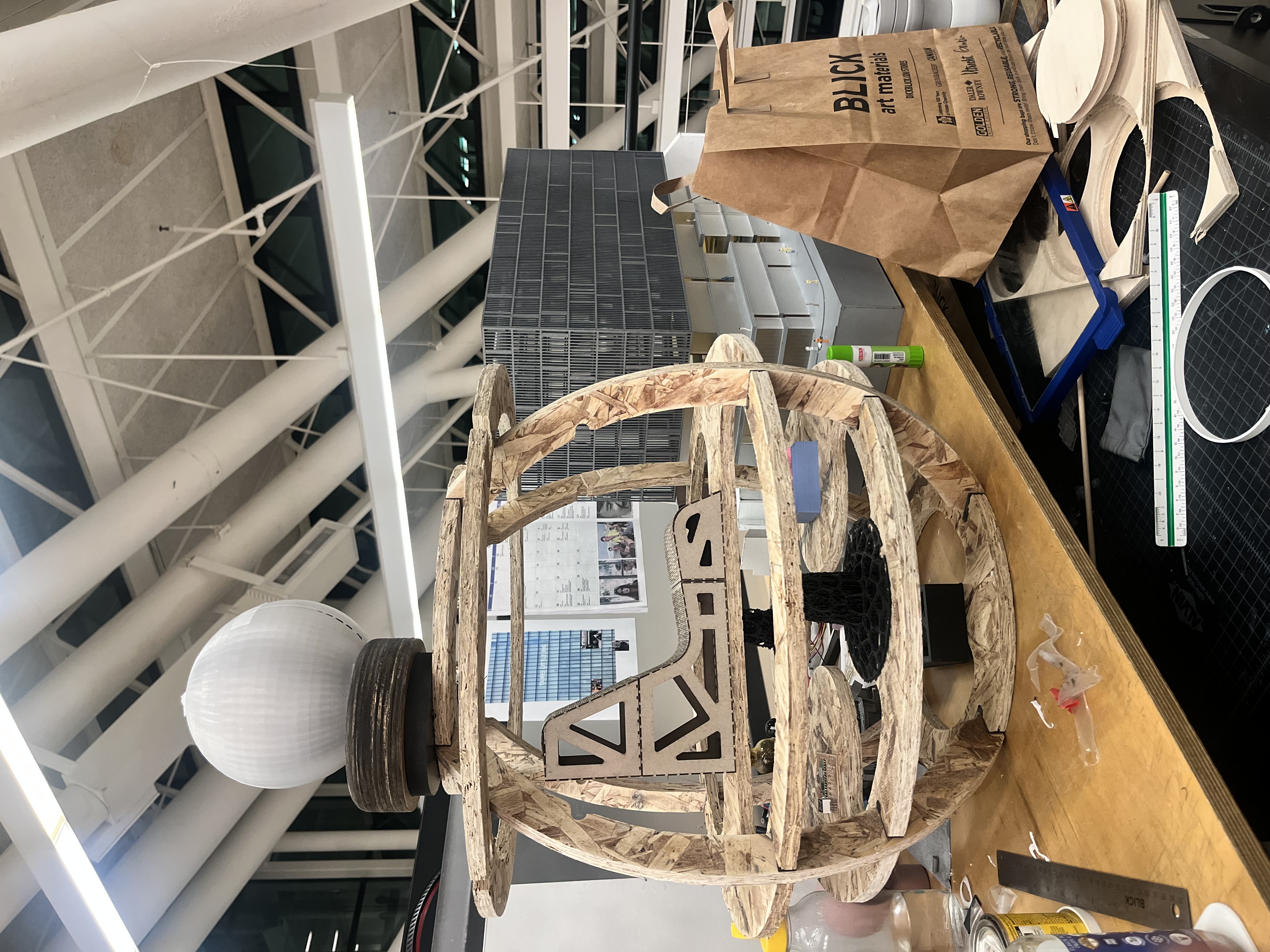
  • The vertical supports and the interior core lock into the base magnet like a foundation in a symmetrical manner to ensure stability when the sphere floats. The LED rings then strap onto the verticals and the outer sphere clips at the top and bottom rings. The maglev system works in analog by using a ring magnet to float the sphere, and 4 electromagnets to stabilize the sphere in the x and y axis. The Hall effect sensors detect the position of the sphere and adjust the electromagnets accordingly. It was important that the top of the plywood base was thin enough to maximise the height that the sphere could float.


  • /TRACKING 12.12.24/ THE BASE

    While I waited for orders to arrive, I began assembling the base. I CNC'ed plywood sheets into several ring sections and then laminated them together with wood glue. Once the glue set, I stained the base to give it the Walnut texture I was dying for. I thought walnut would give the base a rustic feeling that would contrast the transluscent smoothness of the ball. It looks like I chopped a tree down! Such a natural effect to something machined.


  • The MagLev platform is an analog system that I purchased parts for. I would have liked to reverse engineer the whole process, but I knew time was short with a lot still to do. I tested out the system with an older version of my Interior core prototype, and it floats! The electromagnets are controlled by a potentiometer, and the ring magnet is strong enough to hold the sphere in place. The Hall effect sensors are sensitive enough to detect the sphere's position and adjust the electromagnets accordingly. You need to find the sweet spot in the center to keep it intact for the initial float.
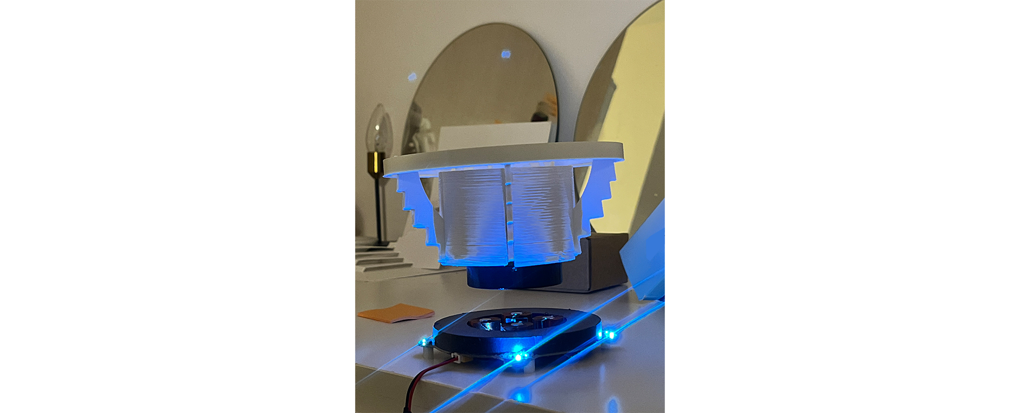


  • As I began to fabricate the frame for the sphere, I tested out the verticals on the base:


    Initially I thought I would have to incorporate a motor to the base to achieve the slight rotation that I sketched out earlier, but the physics of the magnetic field trying to gain stability actually causes the sphere to rotate by itself. The more stable the sphere becomes, the less it rotates over time. A happy surprise! Go physics.


    /TRACKING 12.14.24/ THE SPHERE


    Eventually the LED Rings arrived, and I could start assembly on the sphere. I started prototyping with a Raspberry Pi Pico because initially i thought i would need a lot of pins because I had a lot of rings, but the logic of the led strips actually meant I only needed one pin for data! Since the LEDs can all be wired together and strung to a common power line, as well as only needing one data connection once they were all connected, I eventually moved to the Xiao to keep the interior as compact as I can.
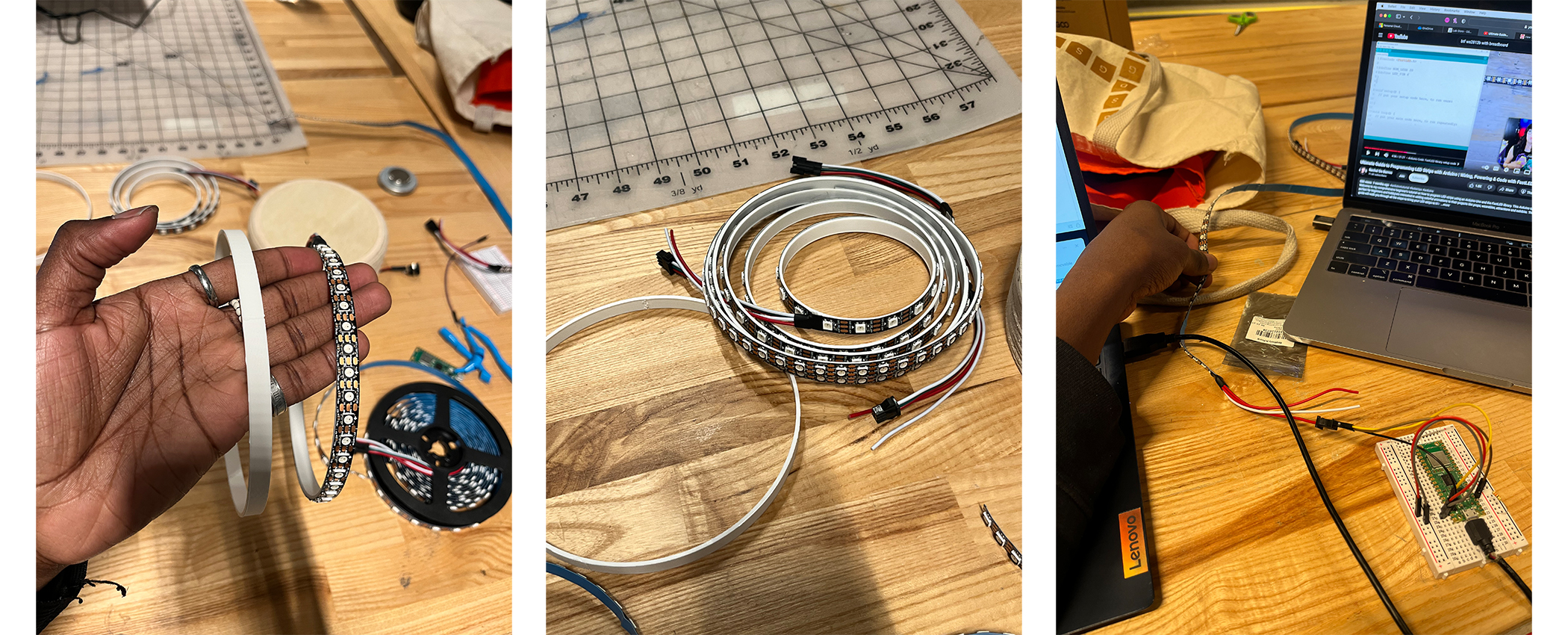


  • I then fabricated the Interior Core. Another power related thing i had to consider was how the LED's could be turned on with all the electronics locked away in the middle of the core. Luckily, the buck concerter has an On/Off switch, so i designed a switch mechanism at the bottom of the core that could trip that switch from the exterior. This was fun to figure out.


    /TRACKING 12.15.24/


    With the core ready, I could test the stability of the power system when floating, and the effect of the LED strip in space. I also printed the Outer Shell with a special PLA that i had to get clearance for. Shoutout to Joe Kyle!


  • /TRACKING 12.16.24/

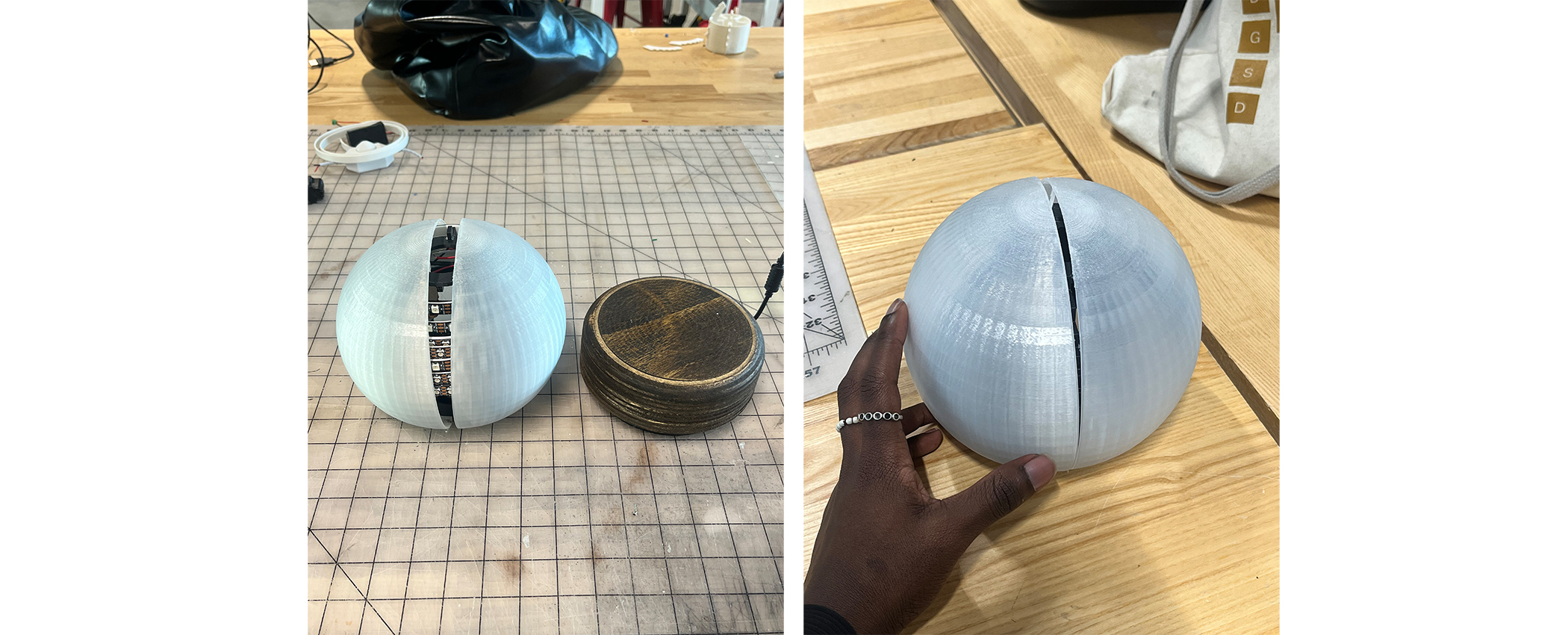
    Time for system integration. I had to drill holes in all the LED strips and wire and solder them all which took a bit of time, so I was losing confidence that I would be able to power the ball in time for review. Nevertheless, I marched on.


  • /TRACKING 12.17.24/


    Ran out of Time. While all the functional elements of the project are present, and the product is acheiving the aesthetic qualities I was aiming for, it is not yet up to full functionality. But it will be. I feel inspired by this idea and will bring it to full fruition next semester. Magic awaits.
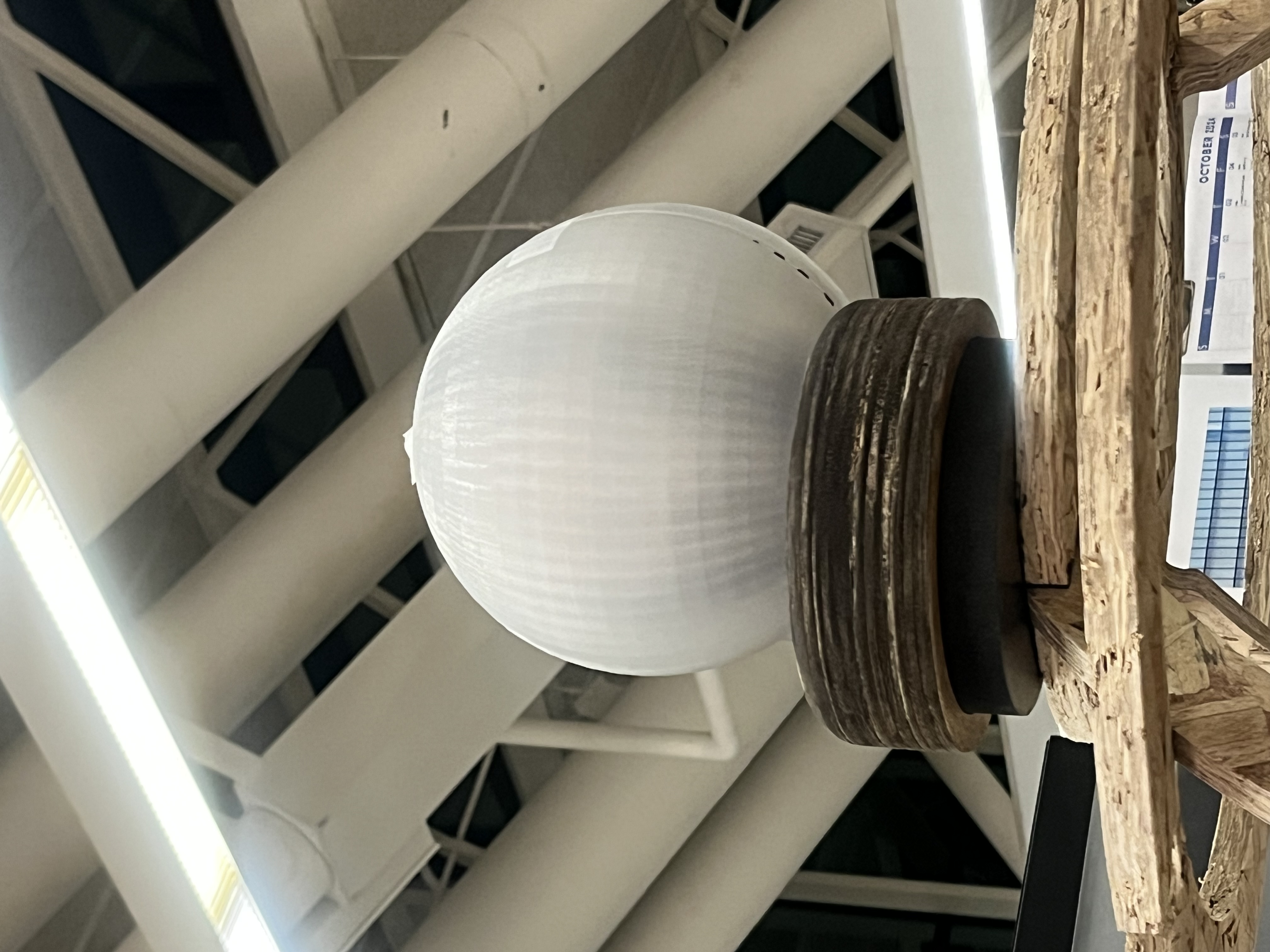


  • Bonus: My little sphere, my big sphere housing my weekly projects, and my big building for my architecture studio at the GSD. It's been a rewarding challenge taking this class on alongside an Architecture studio, but I think i rose to the challenge and developed a body of work that i'm incredibly proud of. I spent alot of time outside my comfort zone and honed in on my expertise. Here's to making more of anything.


  • FINALFINALFINALFINALFINALFINALFINALFINALFINALFINALFINALFINALFINALFINAL