
This week, I started off thinking about my final project idea (which was an enhanced alarm clock at the time) and thought I would want to design a PCB to connect an ESP32 microcontroller to a microphone, speaker, screen, and several buttons and potentiometers. With a little bit of googling and common sense, I realized I needed to start a lot smaller, given I had never designed a circuit or built a PCB before in my life. I wasn't able to make it to recitation this week, which left me even more in the dark with a lot of head scratching and scrolling through previous fab pages. I definitely found some very helpful resources from previous classmates, notably Ani and Merve. After a chat with Anthony, I had a bit more direction on how to get started this week, as well as a pivot on my final project idea which you can find on the Week 1 page! Quick summary: A digital analog clock.
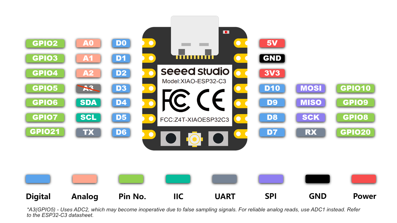
I took a lot of inspiration from Adrian's fabxiao page as I wanted to design a simple breakout board this week. I referenced his schematic to figure out how to use connectors as well as what simple components I could add (LED and switch) to interact with my microcontroller. Anthony advised that an ESP32-C3 would be the best fit for my final project in terms of number of pins, WiFi capability, and size, so I also adapted the schematic to use the ESP32 instead of the RP2040.
I decided to use Eagle, though I tried KiCAD first. I found the component library super overwhelming and most of the documentation I was looking at online or from previous years had used Eagle, so I decided to switch over to that instead.
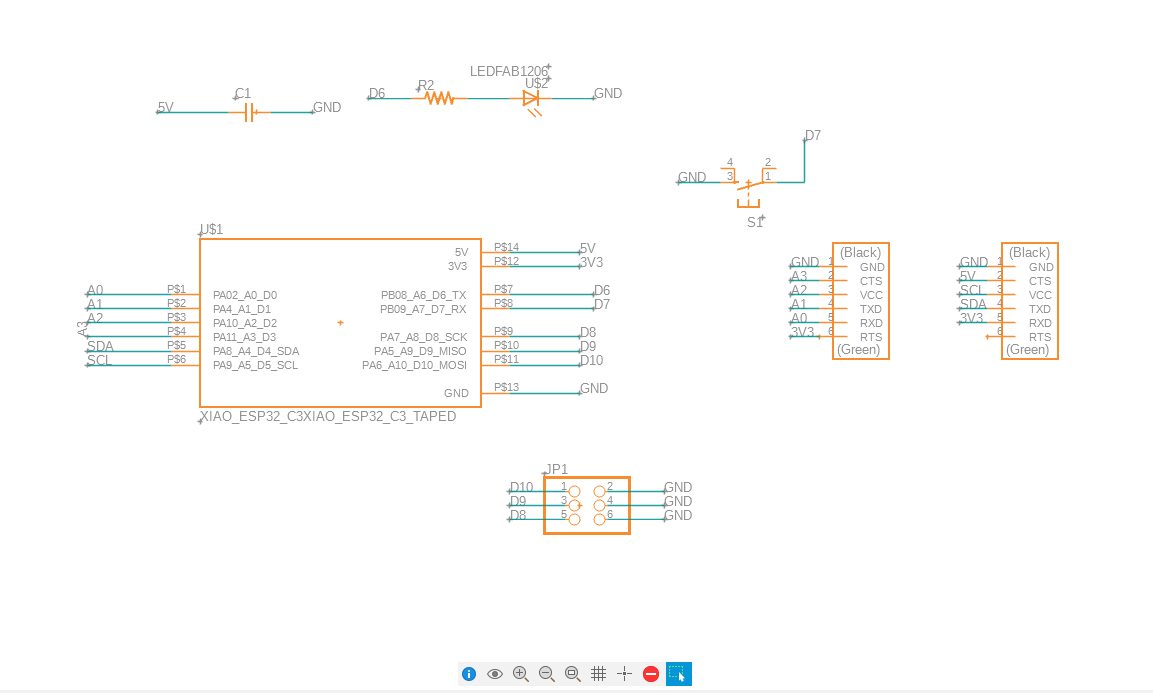
Here is the final schematic for a simple breakout board for the ESP32-C3 with an LED, switch, and several connectors. Not pictured (both out of embarassment and forgotten screenshots) are a resistor connected to 5V and GND, a useless power switch (since power is from the USB-C cable and configured on the microcontroller), and many wrong components, which Anthony directed me away from so that my PCB would be more likely to function and easier to solder to.
Looking at diagrams of PCB routing reminded me of the connect the dots game, which I loved playing on road trips, so I thought I was finally getting to the exciting part of PCB design... Famous last words.

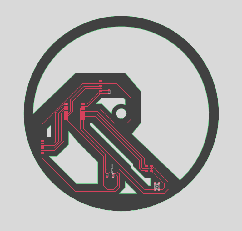
First, I did a few edits to my schematic on advice from Anthony- small switches for connections between analog pins and connectors to make routing a bit easier. I also removed unecessary resistors from my schematic to clean it up a little bit. In terms of visual design, since I wanted my final project to be a fully digital clock resembly a skeletal mechanical watch, I wanted to make my pcb circular with some cutouts.
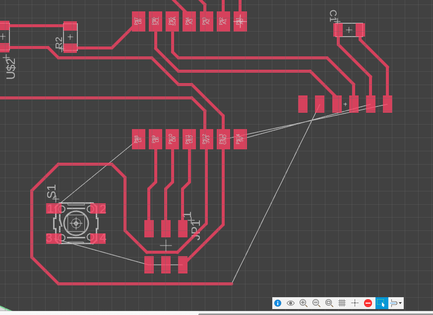
I spent a long time fiddling around before I realized that I had an impossible connection. I've captured part of it here in this screenshot- it's possible that there was a solution, but in my one to two hours of attempting, I couldn't find a way to connect all necessary restraints.
I decided to rearrange by components, doing some rotating and moving elements around to try again. Here you can see the circular layout that I wanted to design around.
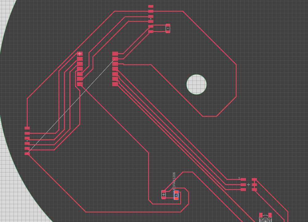
Everything was going well until I though I found myself in the same position with a final connection I couldn't figure out...
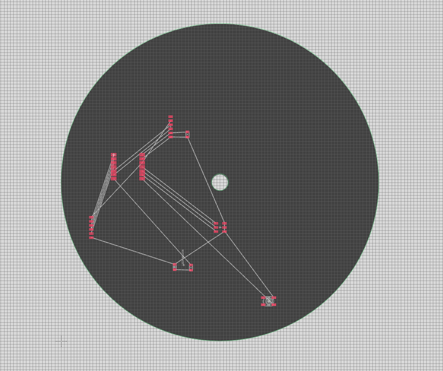
Luckily I was able to figure out a connection between the connector GND pin and the GND connection of the LED. Is this valid for PCB design? I honestly don't know, so I will have to ask Anthony and face the consequences next week. I did end up with a fully connected circuit board and made some cutouts so that it resembled a piece within a mechanical watch.
Overall, I'm quite content with the progress I made this week, having never worked with a circuit board before. I definitely feel a gap between my knowledge of circuits and actual application of putting components on a board and figuring out what needs to be connected but I definitely feel more confident in figuring it out. I want to improve in understanding what parts of a datasheet are helpful for PCB design and am excited to iterate on this when we learn how to integrate input and output devices so I can add motors for my clock hands and buttons for alarm setting.