This week, the Wildcard challenge gave me the perfect opportunity to refine my PCB skills with Anthony and revisit my old nemesis from wk7: soldering the tiny 2mm x 3mm color sensor to a copper PCB. It wasn’t as hard as I thought it would be!
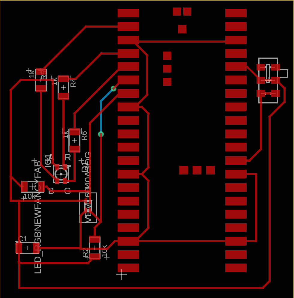
I updated my previous design to include an RGB LED. This addition illuminates the area where the color sensor operates, enabling the setup to emit any hue of light. This means I can analyze colors under various lighting conditions: red under good lighting condition, red under marine blue, red under marshmallow white—you get the idea.
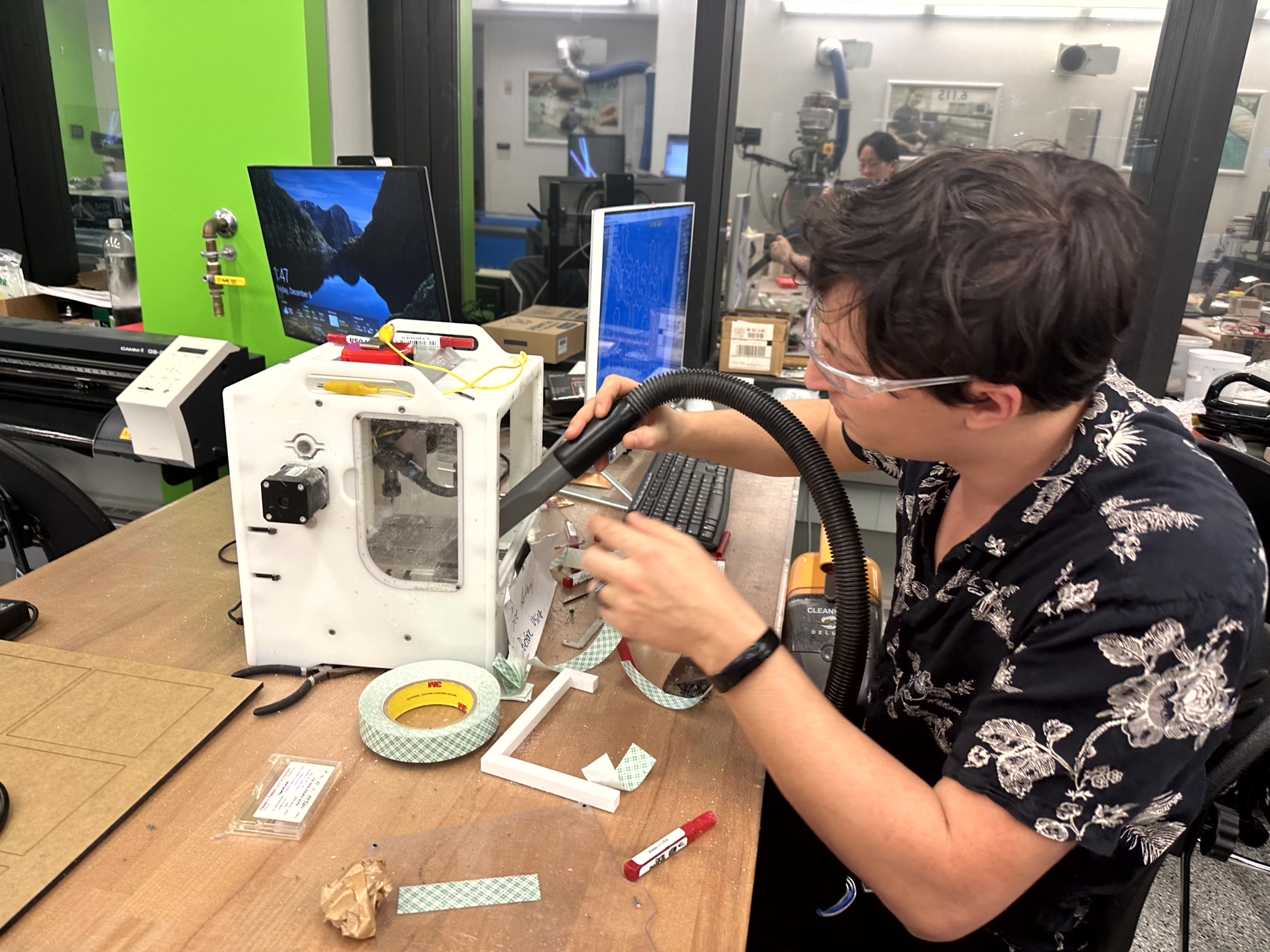
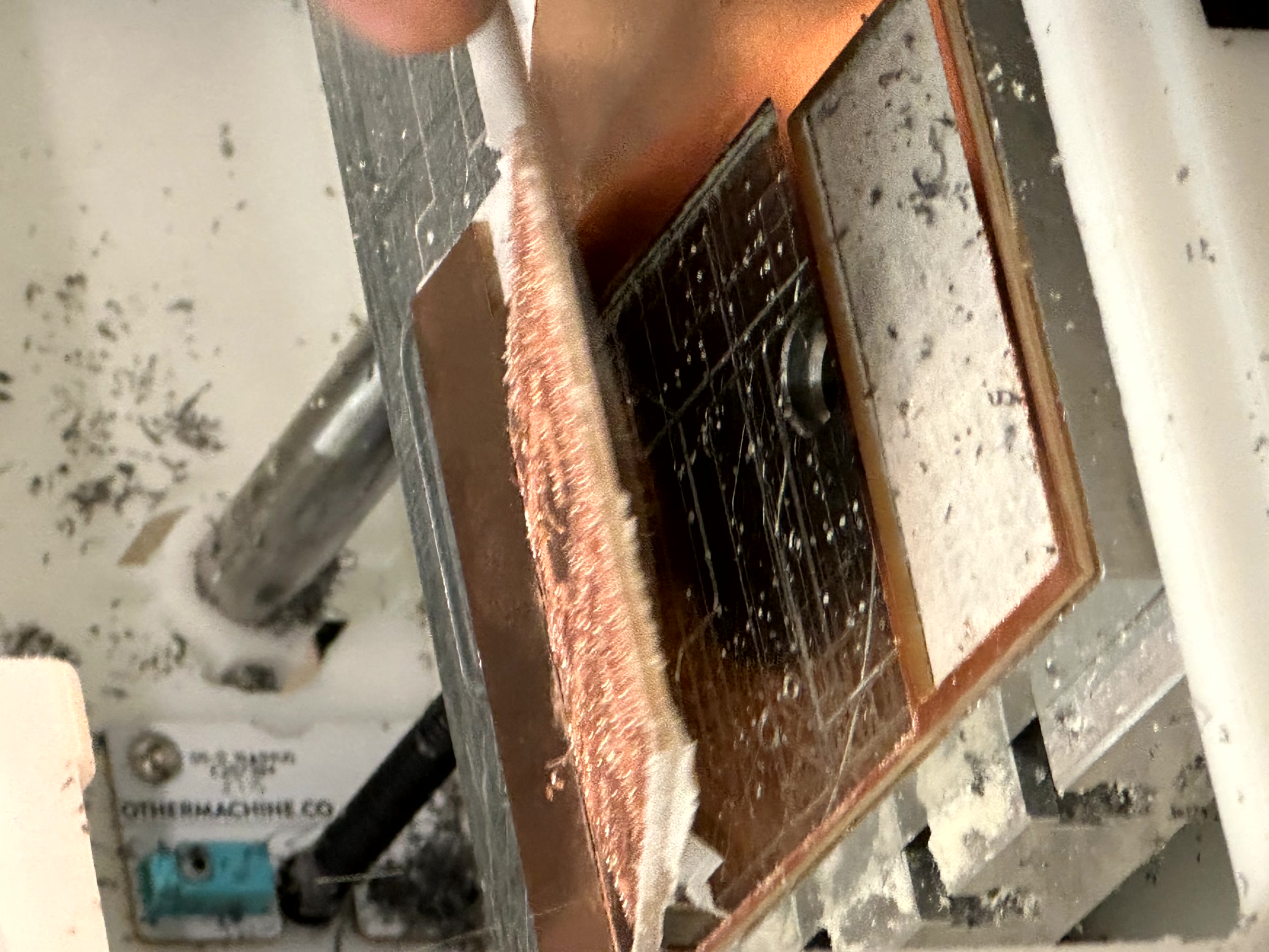
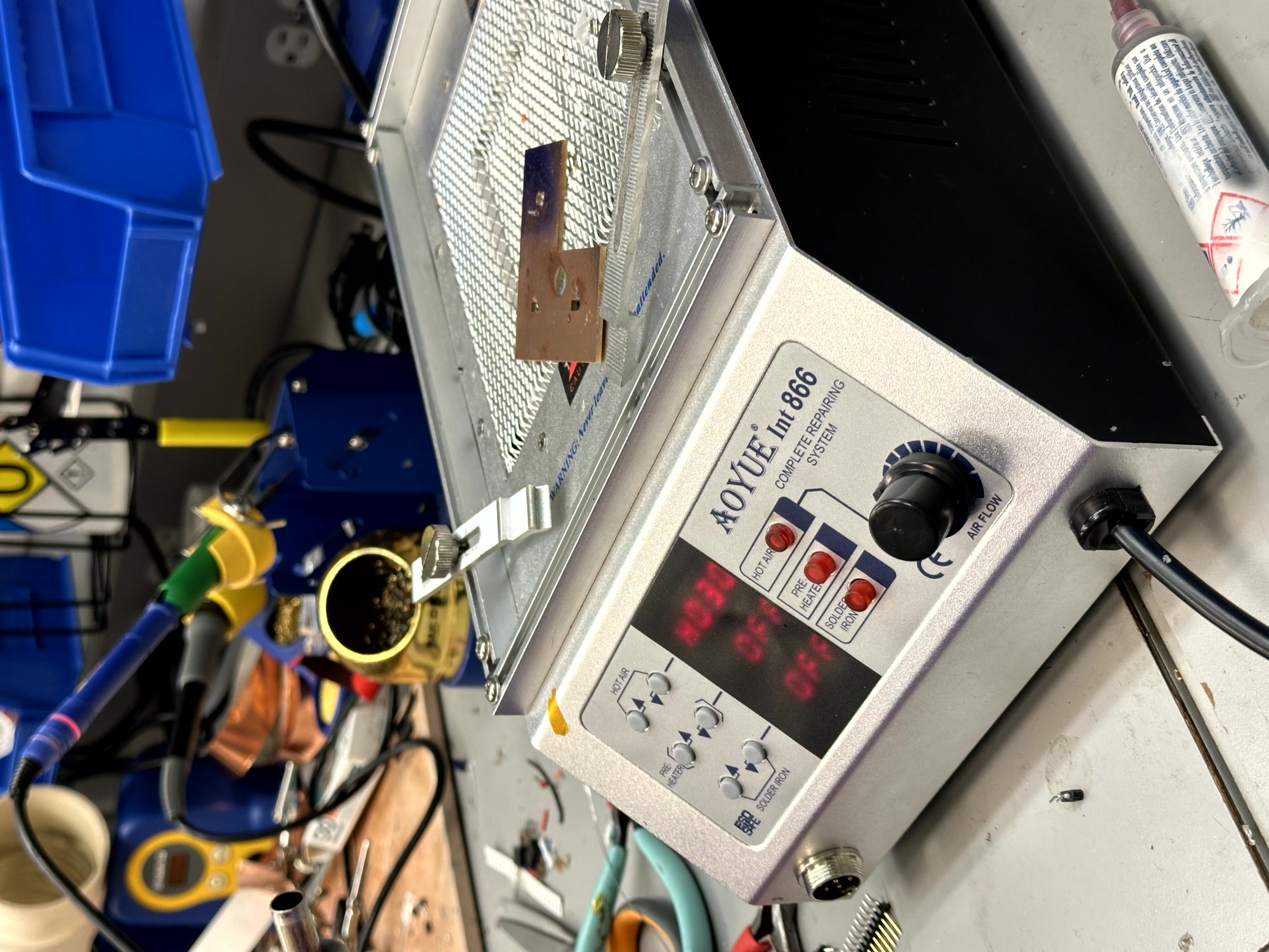
The cutting and soldering issues that caused me much pain was much resolved. Introducing the Othermill (yes, that’s the machine’s name) for precise board cutting, and a syringe with soldering paste for some controlled micro-soldering. Originally, Anthony’s Wildcard idea involved a fiber laser and FR4, but the laser wasn’t cutting well, so we switched to this setup with smaller tools.
The Enhanced Workflow The process wasn’t wildly different from standard PCB-making, but a few extra steps made all the difference:
Schematic Design (Fusion 360): Plan the connections.>>
PCB Layout (Fusion 360): Arrange components logically.>>
Mill the PCB: Skip the gerber2image step since the Othermill takes files directly.>>
Clean Copper Traces: The machine’s speed and precision come at a cost—extra copper debris, which I carefully scraped off to prevent short circuits.>>
Flashlight Check: Shine a light through the board to verify trace integrity.>>
Apply Solder Paste: Cover 80% of each footprint—this allows the paste to flatten and shrink properly during heating.>>
Solder with Heat Gun: Use 270–330°C, holding half an inch above the components. White plastic parts are prone to melting, so careful heat control is key.>>
Lead-Free Solder: Use this for larger or heat-sensitive components to avoid damage.>>
Test Connections: With the board assembled, verify connectivity with a multimeter.

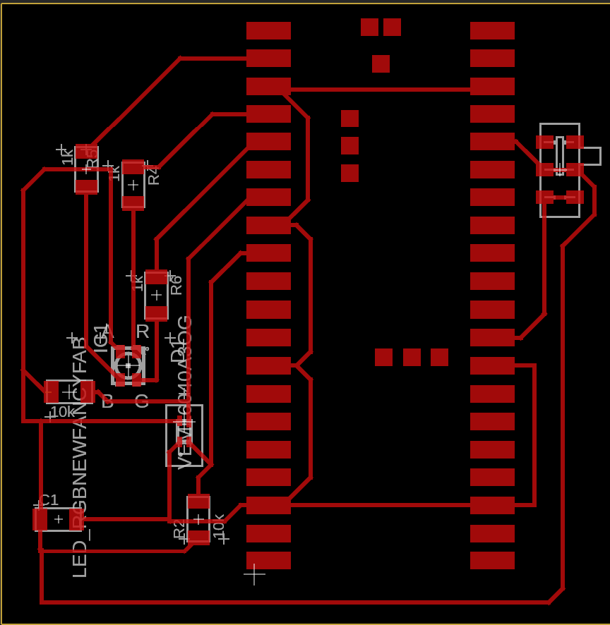
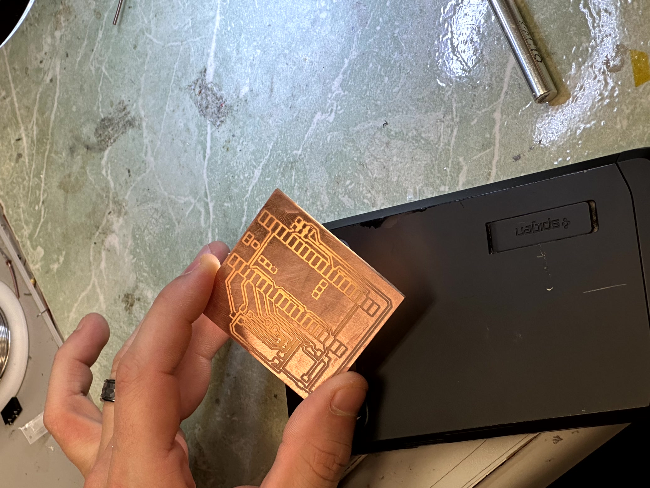
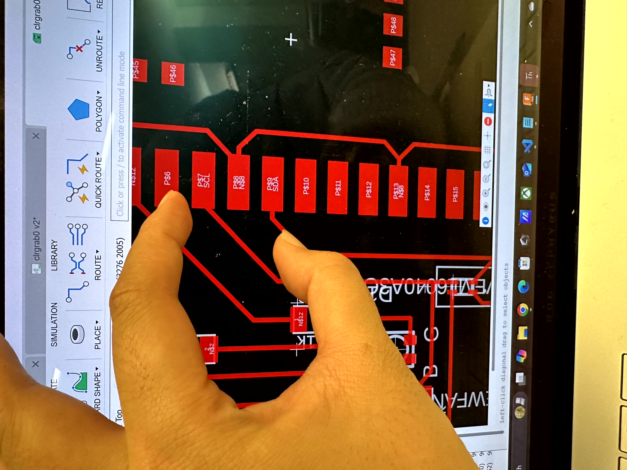
After the physical build, I hit the programming hurdle: getting the color sensor to communicate with the Raspberry Pi Pico. It took hours of troubleshooting to track down the issues. My breakthrough? Breaking the problem into smaller pieces and testing each component individually.
Here’s how I solved the major snags:
SDA Misconnection: Realized the SDA was wired to the wrong pin—fixed with a jumper wire.>> RGB LED Misbehavior: Isolated the switch and LED, discovering that the default brightness was too high to notice subtle color changes.>> Sensor Communication Issues: Tested wiring, I2C address, and various code versions. Eventually, I wrote an isolated function to initialize the sensor, and it finally worked!
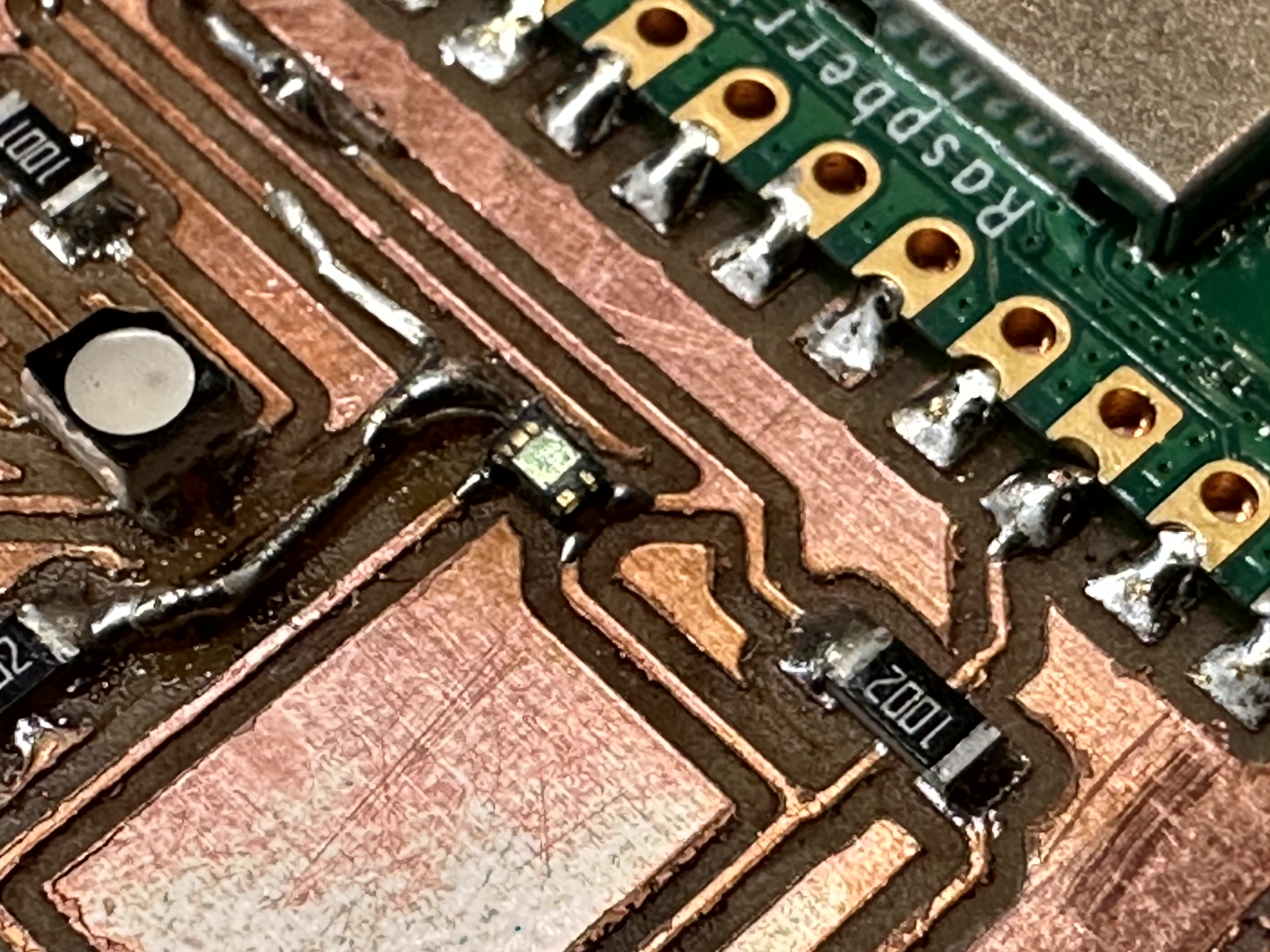
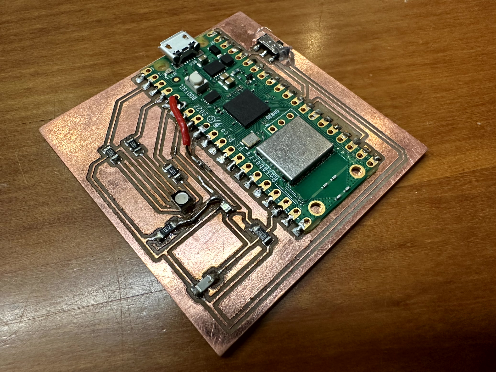
It took a few hours to make component talk to each other and eventually I was able to prescribe a shade of RGB to the LED and sense the ambient color through the sensor. Though the RGB alignment hasn't been coded yet and the color sensor grabs always has a very low normalized data...something to fix in later rendition.