For the major setback in week 5, I decided to go back to basics and start testing circuits on a breadboard. Big thanks to Champa from the EE lab for showing me the ropes of breadboard testing!
Here’s what I learned about breadboards:
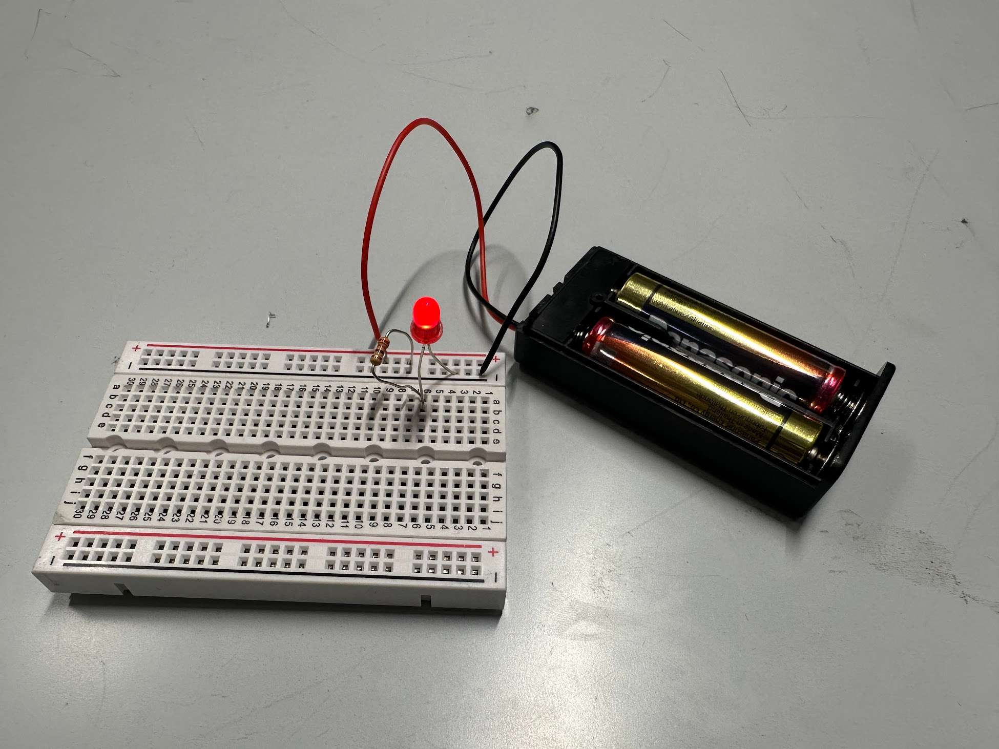
The grid system on the breadboard works like this: all the vertical strips under the "+" or "-" signs are connected in sequence and should be linked to VCC and GND, respectively. The horizontal strips in the middle are also connected in sequence.
Why does this work? Simple: the strips inside the breadboard connect the holes together. It’s like magic, but with more plastic.
Insert two legs of components into holes on different rows or between the VCC/GND and middle rows to create a voltage difference.
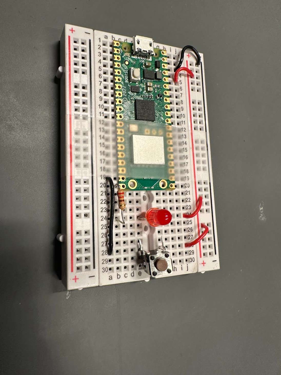
Use jumper wires to connect components. Don’t forget to add resistors to control the current flow!
 Chose 3V battery pack as a resemblance to 3.3V of Pi Pico.
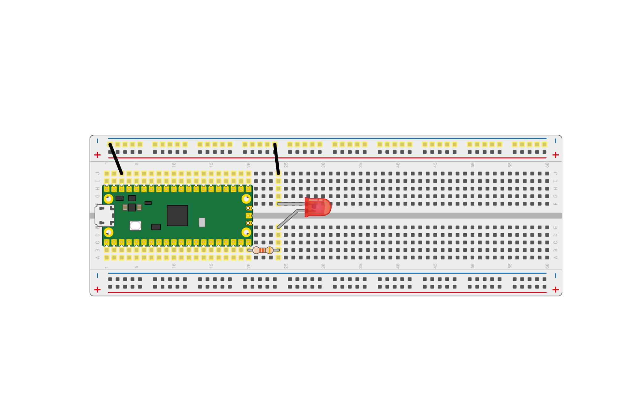
 I wired the board in accordance to the test circuit on Pi Pico Thonny page.
 Before connecting to power, always check for short circuits with a multimeter.
I managed to code Pi Pico for the first time Through Thonny.
 I followed the Pi Pico starter manual to the letter—thanks, Gail and AC, for helping me troubleshooting. I spent a good hour debugging because I missed the little "+" expand button on the firmware installation page... finally got the firmware recognized by Thonny and made the LED blink!
Call back on week 2: the onboard led is blinking morse code of MAY.YOU.GET.RICH