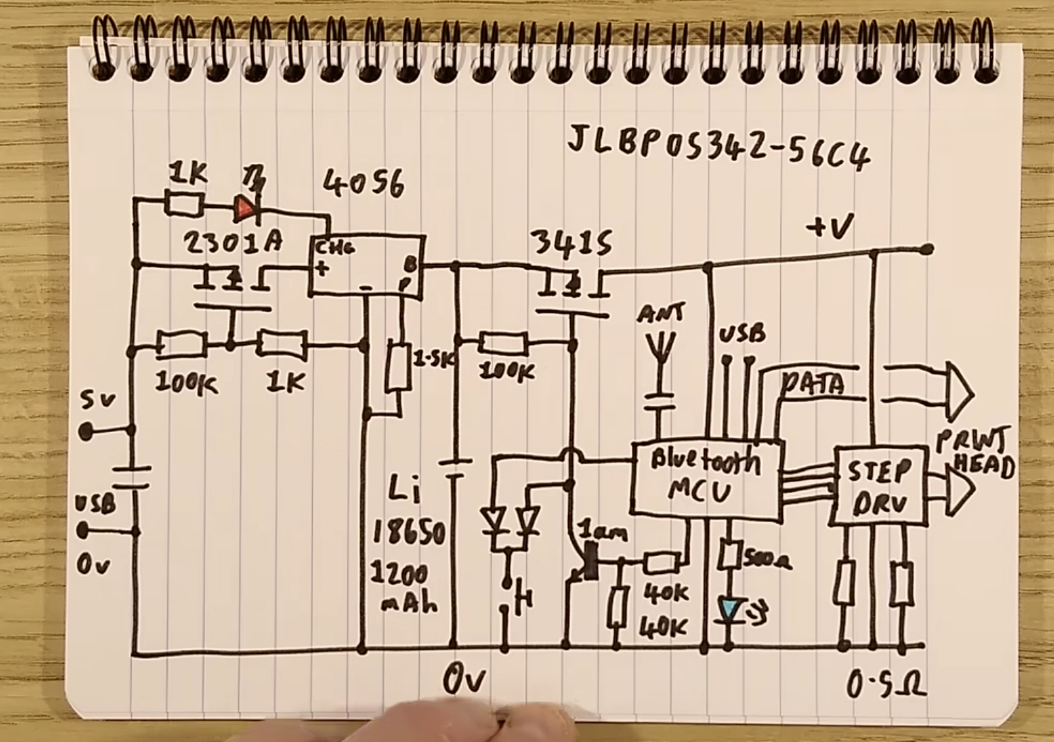
Since I gained a basic understanding last week of how to get an MCU to communicate with an LED, I used this week to analyze a more complex PCB design. The design is part of a Bluetooth thermal printer. A big thank you to TA Anthony for spending hours guiding me through the fundamentals of circuits!
 Here’s what I’ve learned about the functional blocks in the circuit:
1. Power Supply and Charging Circuit
>>5V USB Input: The circuit is powered through a USB input delivering 5V.
>>2301A MOSFET: Likely used for reverse polarity protection or switching the battery voltage source.
>>TP4056 Lithium-Ion Battery Charger IC: Manages charging for the connected 18650 lithium-ion battery (1200 mAh).
>>1kΩ and 100kΩ Resistors: Function as current limiters.
2. Battery and Protection
>>18650 Battery: A lithium-ion battery powers the circuit as a backup for the USB power supply.
>>Overcurrent/Undervoltage Protection: The MOSFET and associated resistors (e.g., 1.5kΩ) likely provide basic battery protection.
3. Step-Up Voltage Regulation
>>341S: Could be a DC converter that boosts the battery voltage to power the rest of the circuit.
>>Capacitor Near 341S: Provides filtering to stabilize the boosted voltage.
4. Bluetooth MCU and Data Processing
>>Bluetooth MCU: Includes an antenna (ANT) for wireless communication.
>>Data Lines (USB, DATA): Enable communication between the MCU and an external device for data transfer.
5. "STEP DRV"
>>Inputs from MCU: The Bluetooth MCU sends control signals to the step driver.
>>Resistance (0.5Ω): Likely used for current sensing.
6. Indicators and Resistors
>>LEDs: Serve as indicators for current flow.
>>Resistors (40kΩ, 1Ω, etc.): Used for signal conditioning and current limiting.
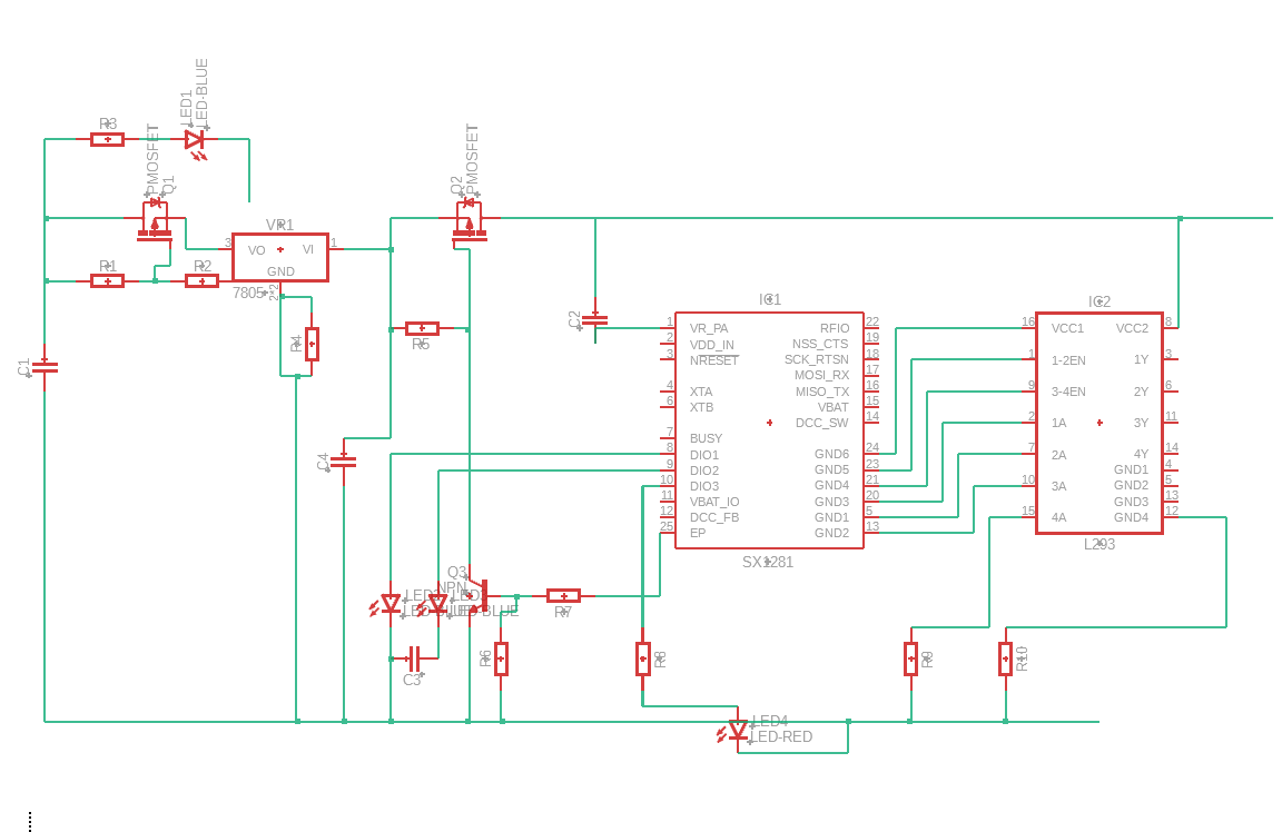
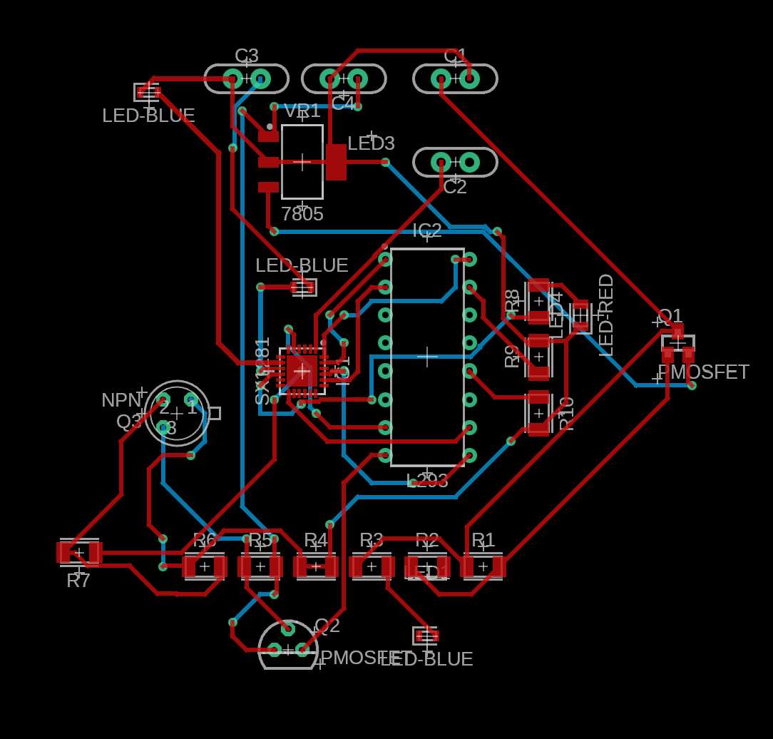
 I attempted to recreate the schematic based on what I learned, but I’m finding it quite challenging to replicate the design as it appears on the PCB. I still need to figure out how to connect the stepper motor to enable the printing feature. Anthony explained how to interface with two stepper motors to control the printer needle.

Stepper motors operate by receiving electrical impulses, which determine their rotation (clockwise or counterclockwise) and the number of steps they take. A simple solution to move the printer needle involves using two stepper motors: one for the x-axis and one for the y-axis. However, the thermal printer showcased is miniaturized, implying the stepper motors are micro-controlled. This technique, called microstepping, divides steps into smaller increments, enabling much more precise control.
Anthony also mentioned a more material-efficient approach to microstepping, though I’m not sure if I fully understood it. The idea seems to be that microsteps don’t necessarily require breaking a large step into uniform small angles. Instead, the motor could combine steps of different sizes. For example, instead of moving 1 × 17 units, the motor could achieve the same result by moving 5 × 4 units in one direction and 3 × 1 units in another.
These are promising theories, but I still need to test them on the actual components. And given my current EE knowledge - I am many pcbs away from this thermal printer design.