Overview
One of my motivations for taking HTMAA was the opportunity to fabricate some of my ideas. My research focus is in urban mobility and I am thinking a lot about autonomous delivery. I think it would be pretty cool to design and develop an urban robotics animal for my final project.
Concept from Week 1
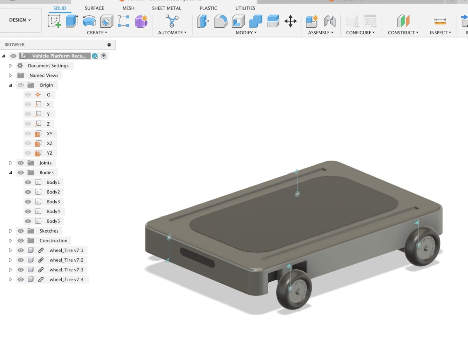
My first idea for the final project was a low profile platform that is fully drive by wire and has on board sensing for autonomy. The vehicle should fit uses for personal mobility, cargo, and various utilities needed in city movement. It should have universal mounting rails on the deck of the vehicle. Maybe it could be transformable between modes? Like the citycar, the city mobility unit should have hub motors to avoid any mechanical linkages that need to transfer power to the wheels. While I think this is cool I think that I can be more creative
More ideation
I would like to push my ideas a bit further than just a moving little platform. Here are some potential candidates:
- MicroBlimp - A soft drone that can move through a city and interact with people (see early prototype)
- Quadruped - A little robot...with Capstan drive maybe using Dyneema or something like that? Lower gear intertia could result in better IMF?
- Panda Robot - My research work is making a little panda inspired robot for delivery. I could work on one of the prototypes in HTMAA. I could make a scale prototype.
- Grasping Mechanisim for Delivery Robot
- HMI for Delivery Robot
- Design a Torque Dense Actuator and controller
The Last meter and Legged Robots
Automated delivery in cities is super difficult since you need to move from the street to the front door.

Moving from the street to the final destination is even less structured than driving in the street. This is why it is such a large bottleneck.

If multifunctional autonomous micromobility was paired with last-meter robots, they could deliver packages during the night or when ridership is low and so you could have smaller fleets and less embodied carbon.

As soon as you leave the street you find that a lot of infrastructure was designed for people and so having legs can be an advantage.

Some wacky ideas on what I could build...
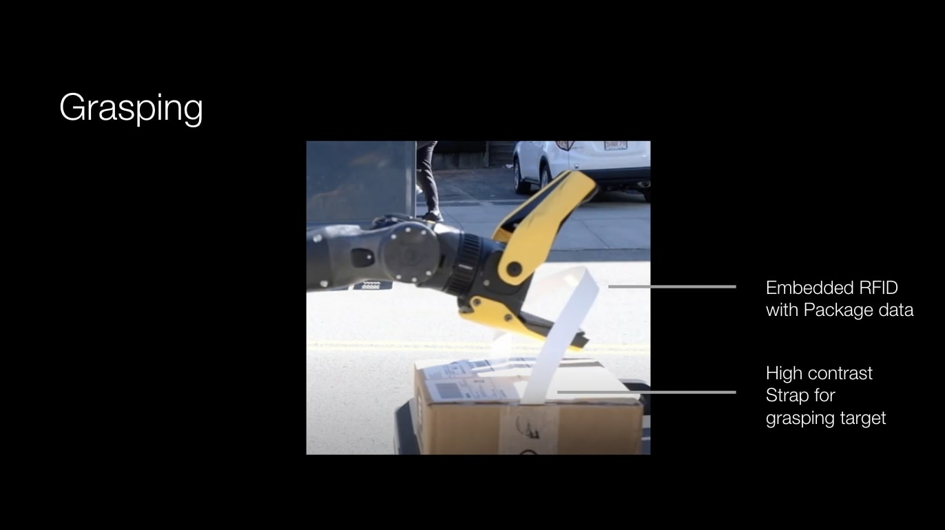
What if we put RFIDs in the straps of a package to let the robot know where it should grab and where the package needs to go?
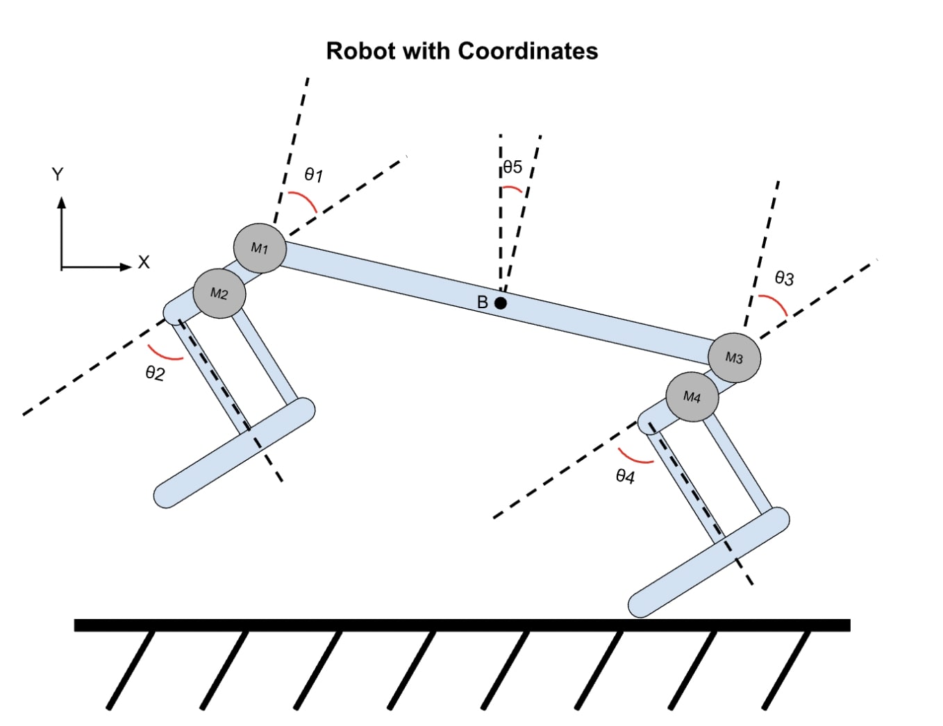
I made a little joint angle diagram of the doggo robot I want to build for moving around a city.
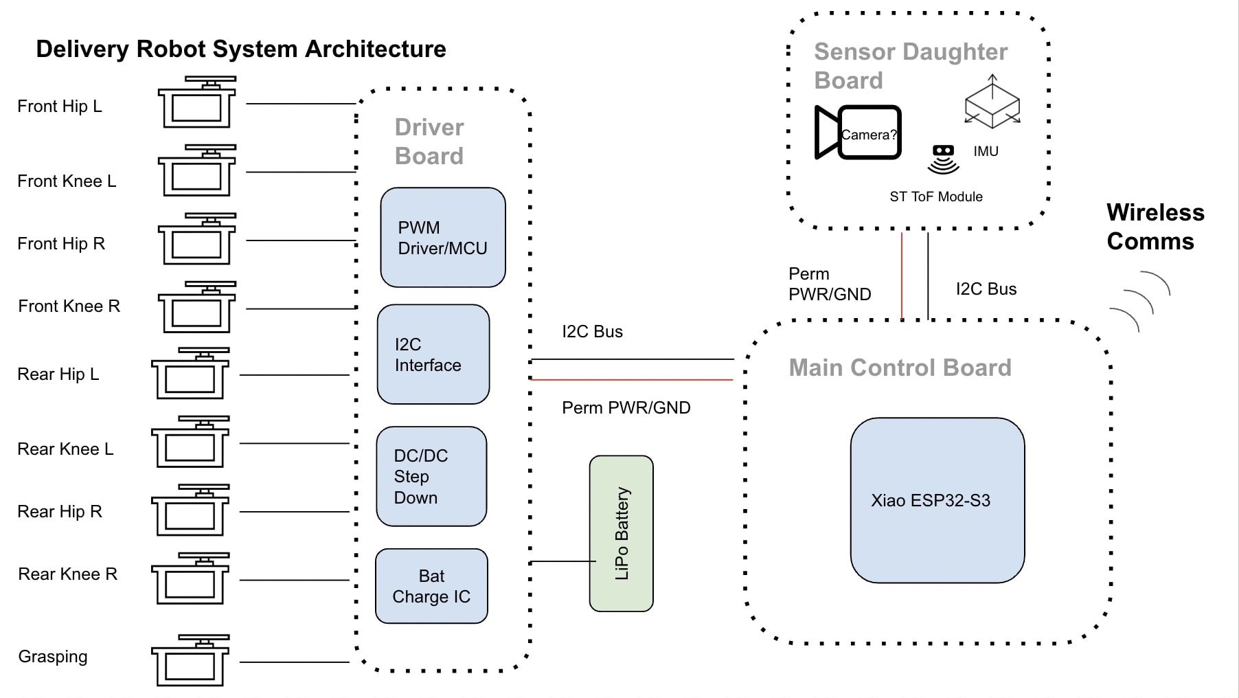
System Architecture Diagram
1 + 8DoF quadruped walking robot.
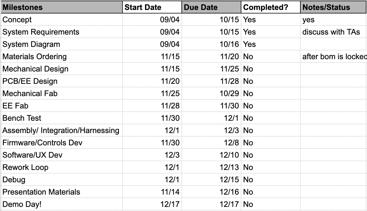
Schedule
Change of Direction
Insert Images of Bio-Inspired Robot and PANDA
I had a very helpful midterm review session with Alfonso where we brainstormed ideas on how to align some of my robotics projects with How to Make. My two main projects I am working on are building a legged running dog and bio-inspired Panda robot for urban parcel deliveries. The Panda robot needs a head and gripper for gasping packages so I will focus on this subsystem for my HTMAA final project.
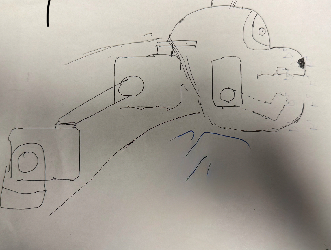
I started to concept out what this PANDA gripper would look like and wanted to start building ASAP. My initial plan was going for a 5-DoF gripper with 3 servos. I later removed the 1-DoF jaw servo and went with 4DoF since the extra degree isn't really needed and can't be packaged into the volume of a sleek neck and head.
Some Main Components
- OLED - I will used these for creating the eyes interface. OLEDs are probably too detailed for this robot but we have them!
- RFID - For reading a RFID tag. Each tag ID could be associated with important package info beyond a name and maybe address that could be kept private istead of a public label (medication, address, sender) so that this info is only known by the recipient and the logistics provider. The tag could also be associated with info helpful to the robot (package dims, weight, temp requirements, fragility).
- Servos - We need soemthing to actuate the robot grasper. We only actually need 2 dof (pitch and jaw) but more degrees can create more of an animated robot!
Dynamixel TTL?
I next 3d printed some links and a base to create a test setup to play around with the Dynamixel servos. I am using Dynamixel servos here so that I can put the gripper on the panda bot after since these are the servos I am using on the panda robot. If you are not familiar, they can be daisy chained and are quite torque dense. Dynamixels are super common in robotics projects BUT they are not just plug and play with a simple PWM output.
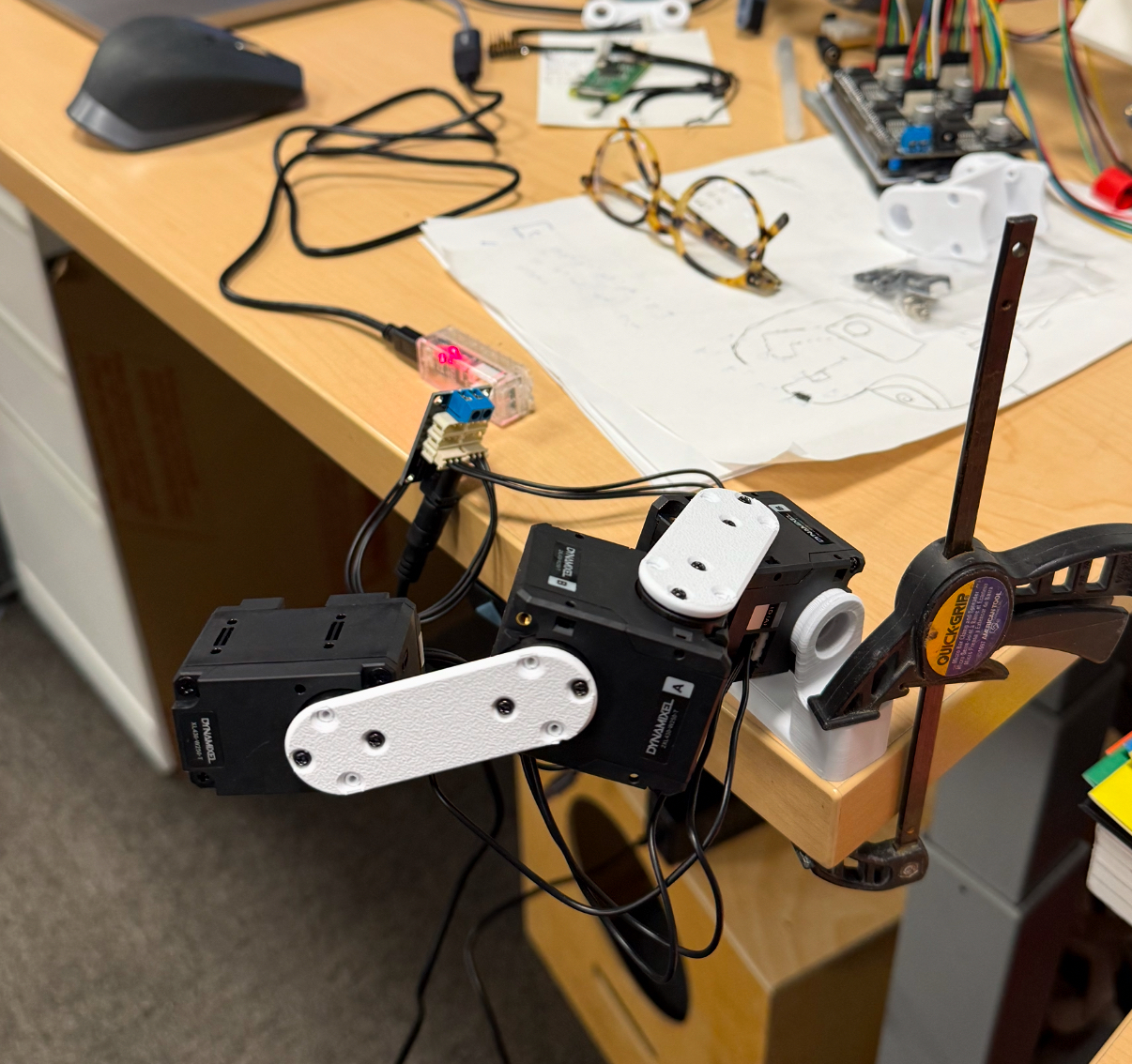
I got the servos moving using the Python sdk for Dynamixels pretty quickly but I was using a U2D2 comms converter and I wanted to control the board with my own code running on an xiao in the true spirit of HTMAA. I used the Dynamixel2Arduino Github which seems to be not that well supported but exists! The protocol is a half-duplex aka only one line for sending and recieving packets. To support this we will tie the Tx via a 5.1k pullup and Rx on the Xiao to the single TTL line on the dynamixel.
I was able to do a single task like blink motor LEDs, move one motor or query the motors for position, temp, etc but the bus would go down if I tried to anything useful like query position and send position commands. After, playing with message timing things (response delays, command spacing) and got some minor improvements it still felt like something was fundamentally wrong with the hardware or with the library. I went to office hours and Quentin asked the intelligent question of "is the logic level 3.3v or 5v for the TTL line?" The xiao Rx and Tx are at 3.3v and the dynamixel's logic is 5v. Looking at the time I spent on servo bringup and the limited pins left on the xiao I decided to concede to the U2D2. Next time...
System Diagram and BOM

I mapped out the system architecture of my final project which helped me draft a BOM for the project.
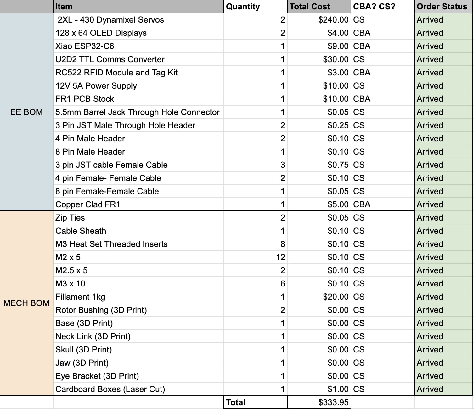
I made sure that I have enough components for final project by creating a final BOM. I reused a Xiao from my earlier weeks
Making it
Now that servo control was sorted, the next largest risk item is making sure all the modules can work and work together. First up is the bringup for the RFID module.
Electronics
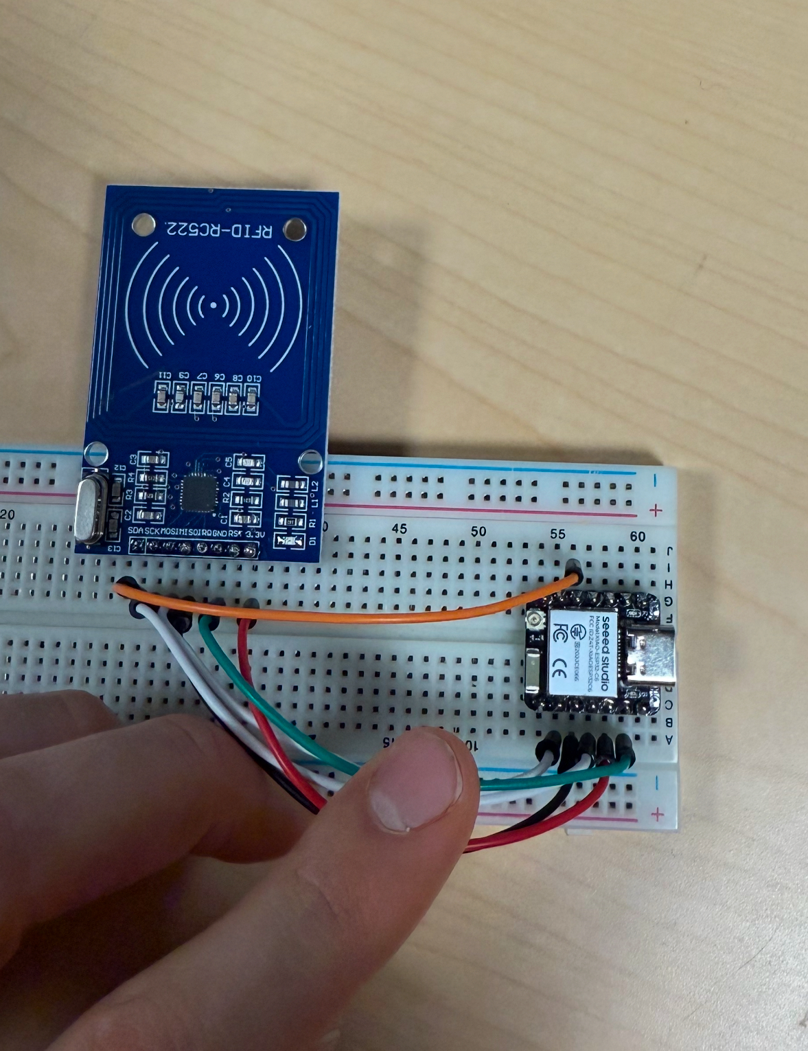
When I was looking at the documentation for the RC522 I saw that there was an I2C interface and so I thought that it would be nice to have the displays and the RFID reader all on the same bus. After wiring the module I realized that the I2C isn't accessible so I switched the wiring to SPI.
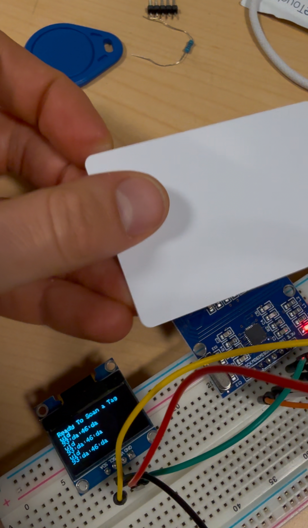
Next up was the display bringup and checking that we can scan and use the display at the same time
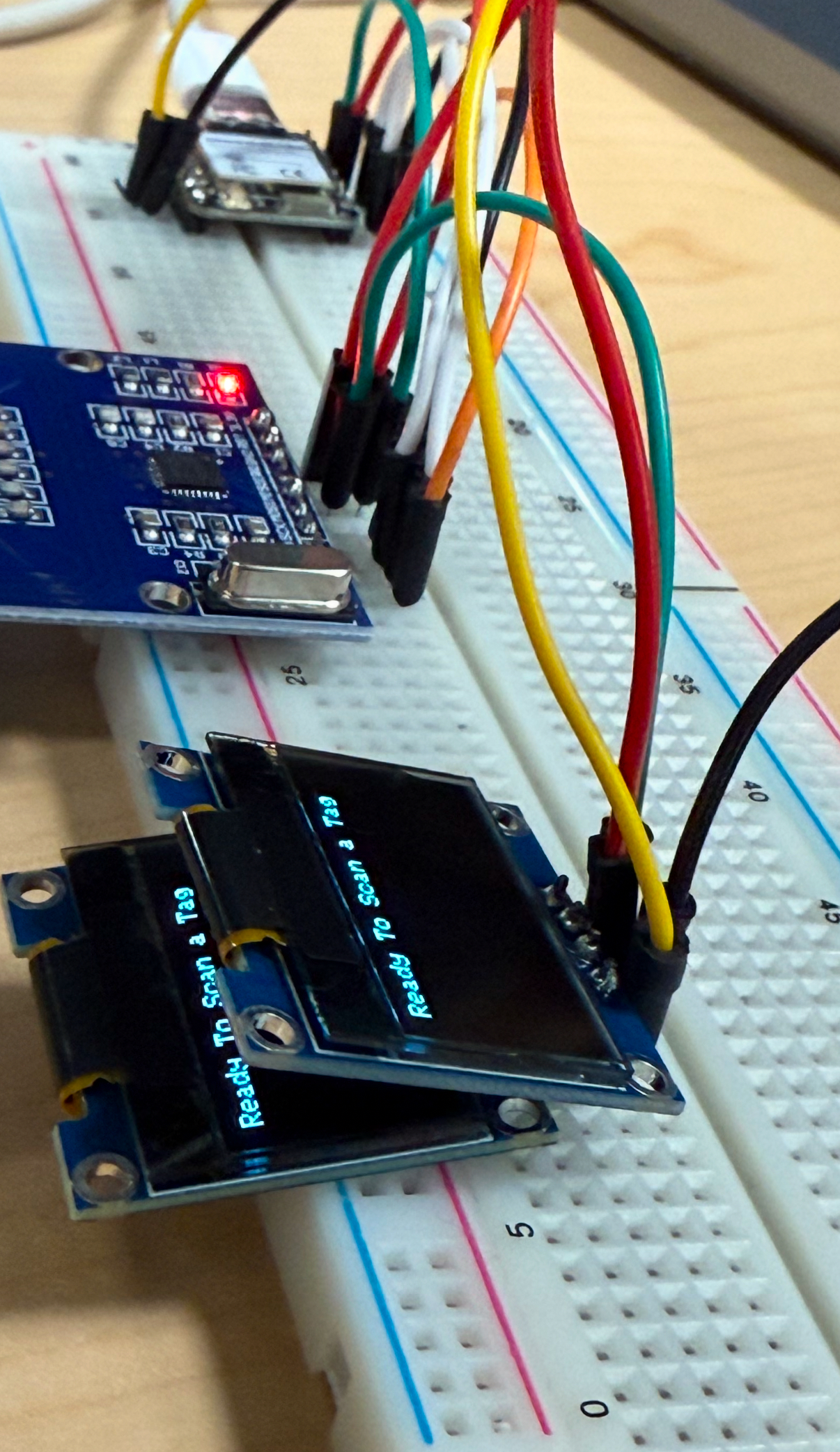
Okay, one display is cool but can do do two?? Can our little xiao's 3.3v pin supply enough current? Yes.
PCB
Now that all the electronics work we are ready to design the PCB. I will work in eagle within fusion to design the PCB.

I will not accept the use of jump resistors for a simple module board.

This is a panda robot so why not make the PCB that no one will see cute too (found a cool free icon by Riajul via flaticon).
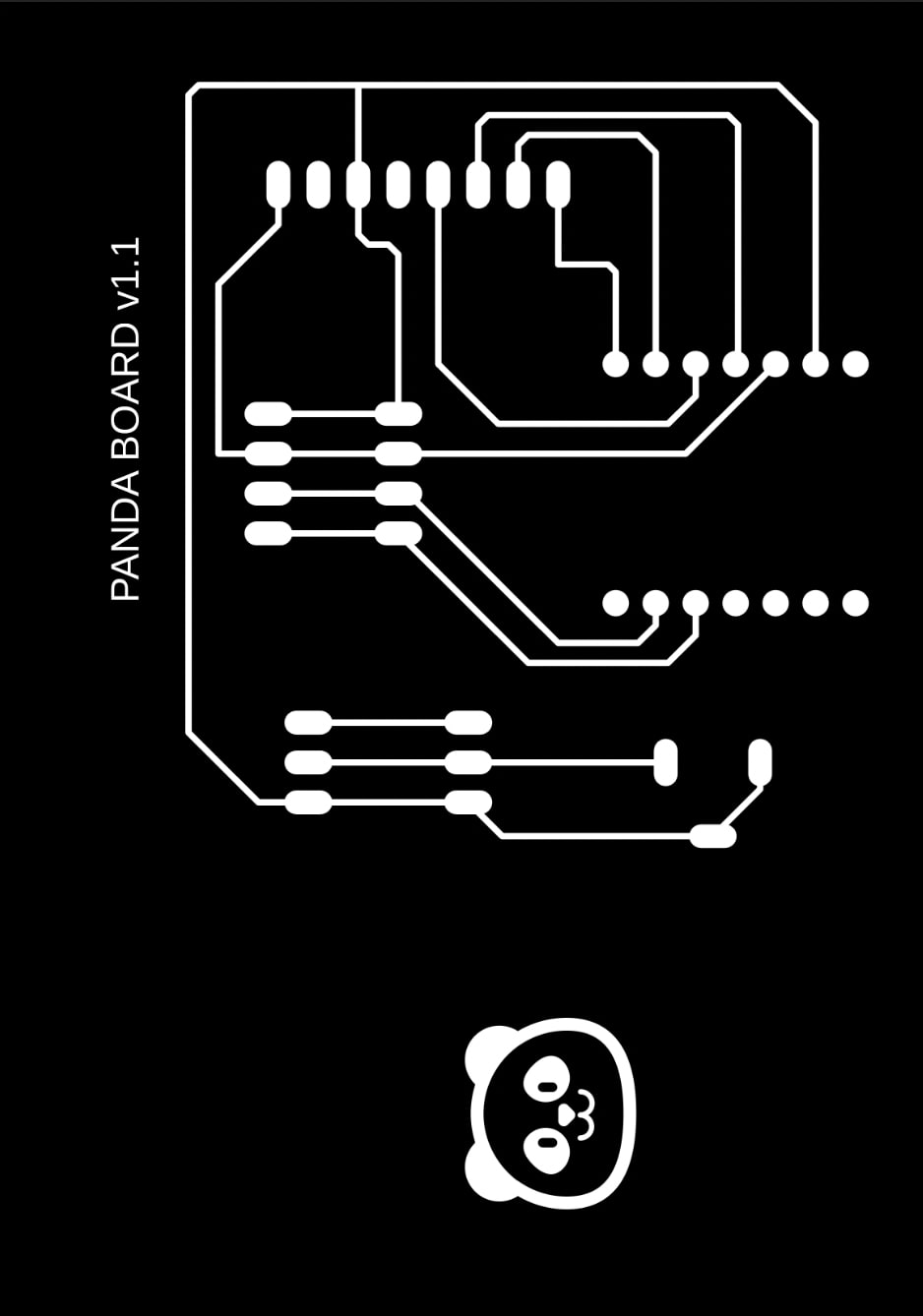
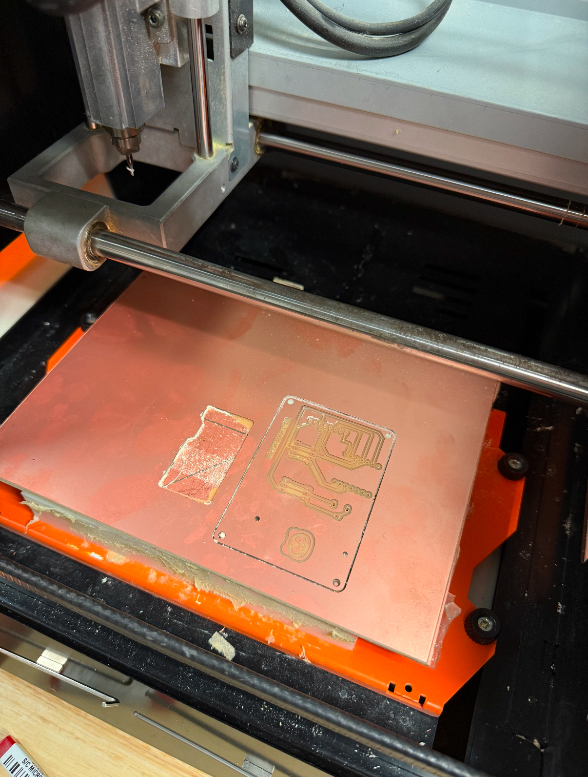
The luxurious carvera had a long queue but Miana was kind enough to teach me how to mill on the Roland! I love this little machine.
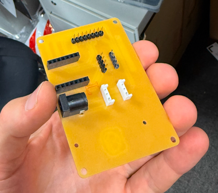
Solder it up and populate the board.
Next task was to design a simple case for the control board. It would be nicer to have panel mount connectors but I simply used what we had in stock at city science.
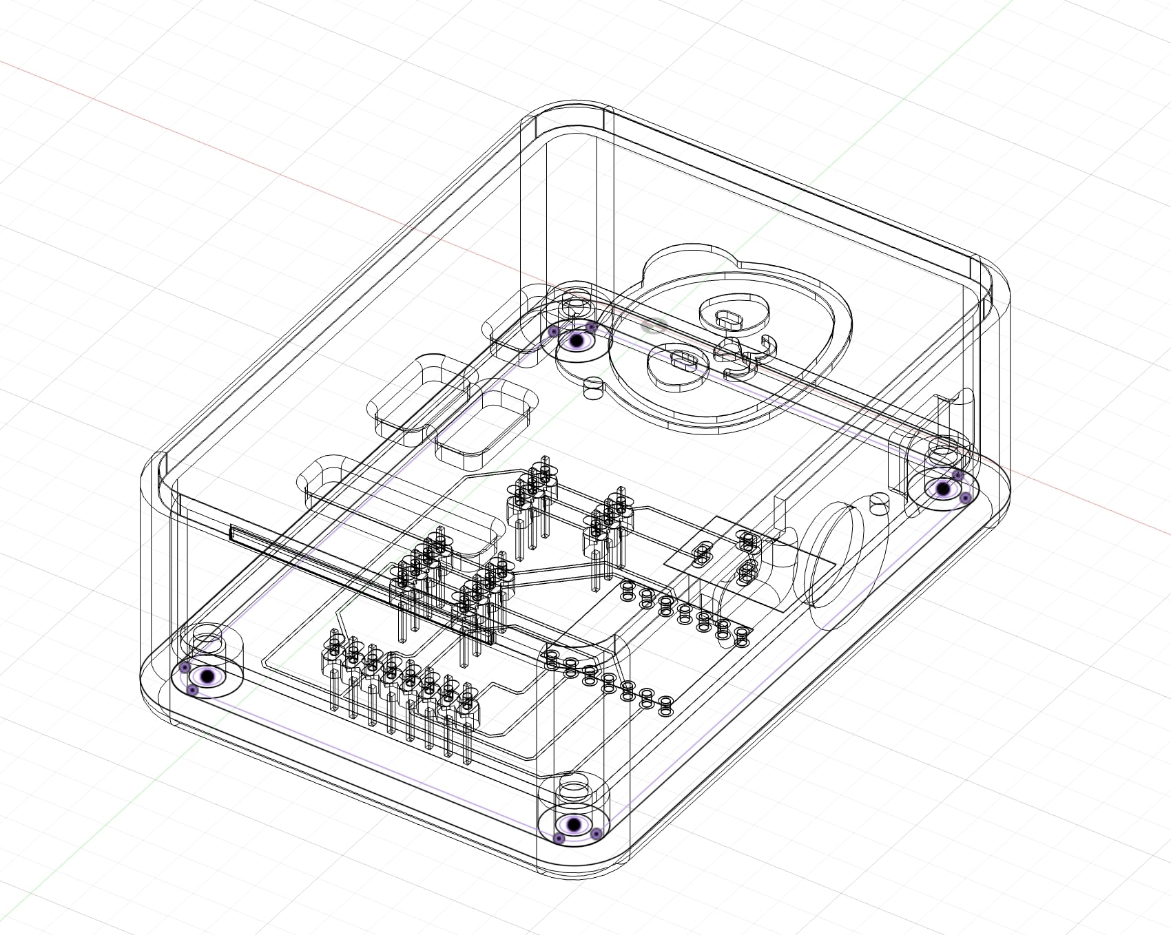
I put some nice melt-in threaded inserts just because.
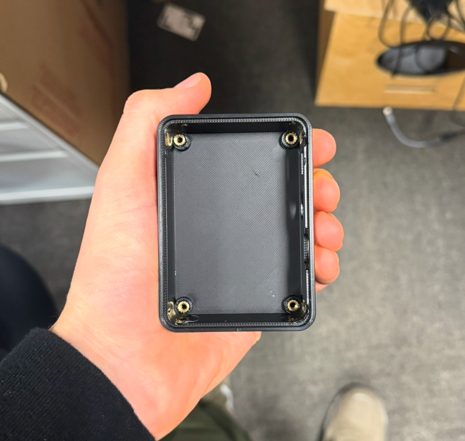
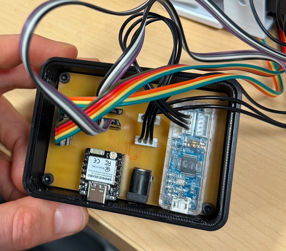
Time to assemble the board in the case and wire it up to make sure that everything still works.
Mechanical
I now needed to design something to hold the displays, RFID module, and grasp a package. First I made the skull for the panda. Super basic and ugly but I wanted to make sure I could have something that met all the requirements before refining everything. We will be 3D printing all the mechanical components here.
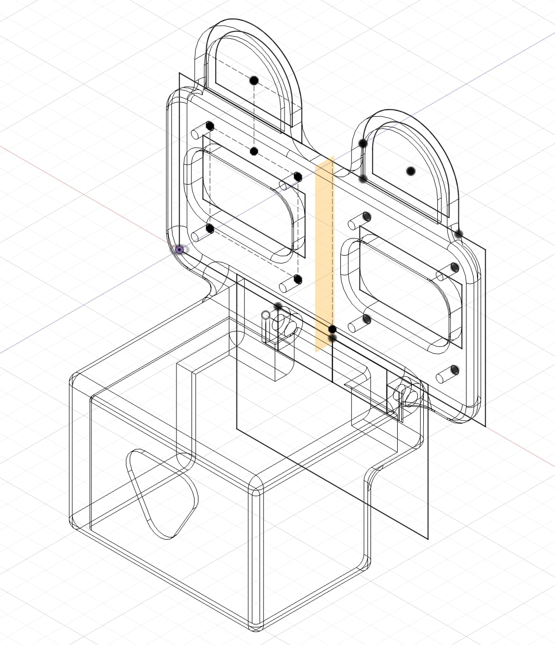
The jaw needs to grab a loop for holding a package and also scan a RFID tag.
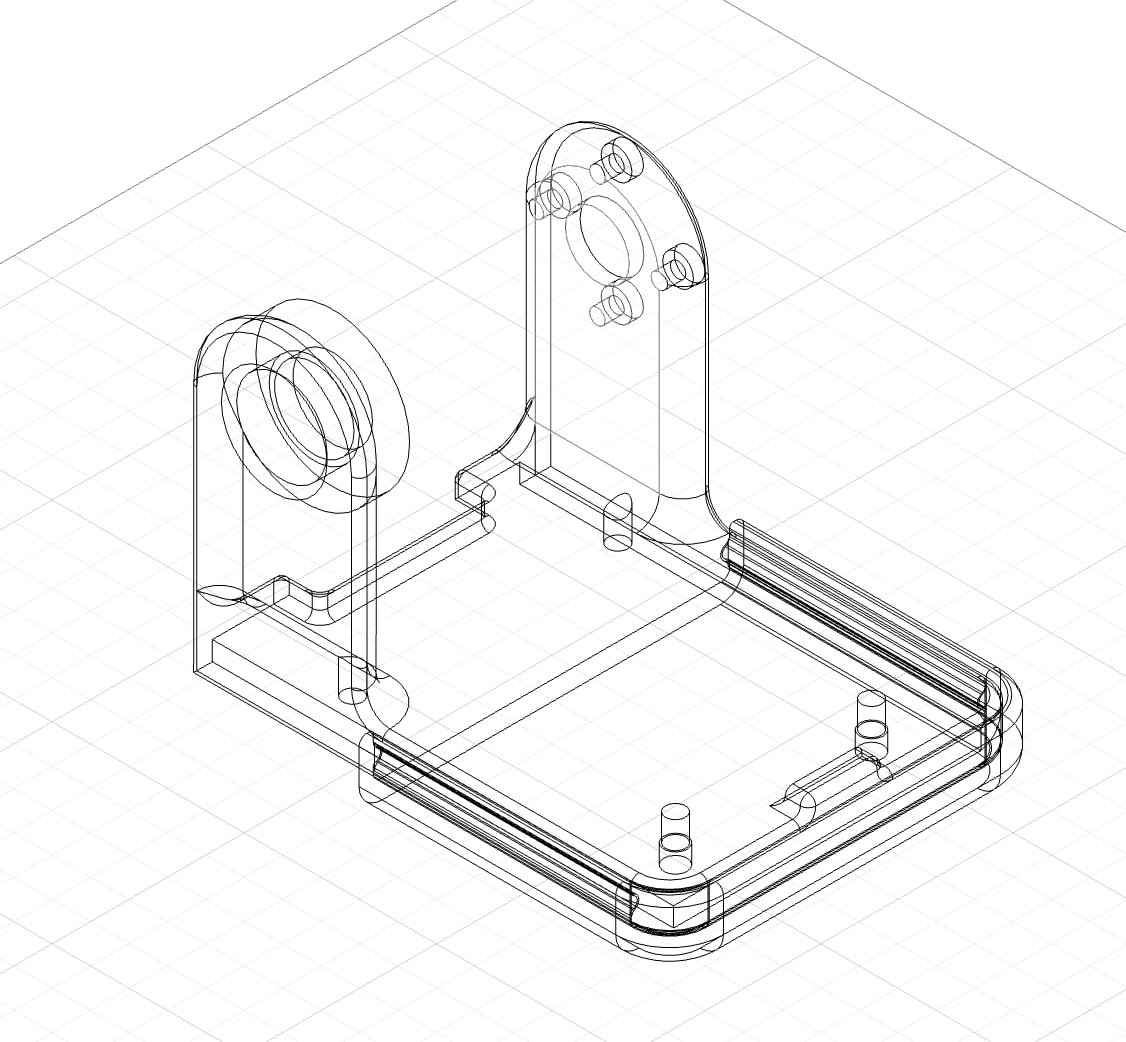
~~~Design~~~
Although this "panda" technically meets the requirements for HTMAA, this thing is terrifying and doesn't look like a panda. It's time to make it pretty
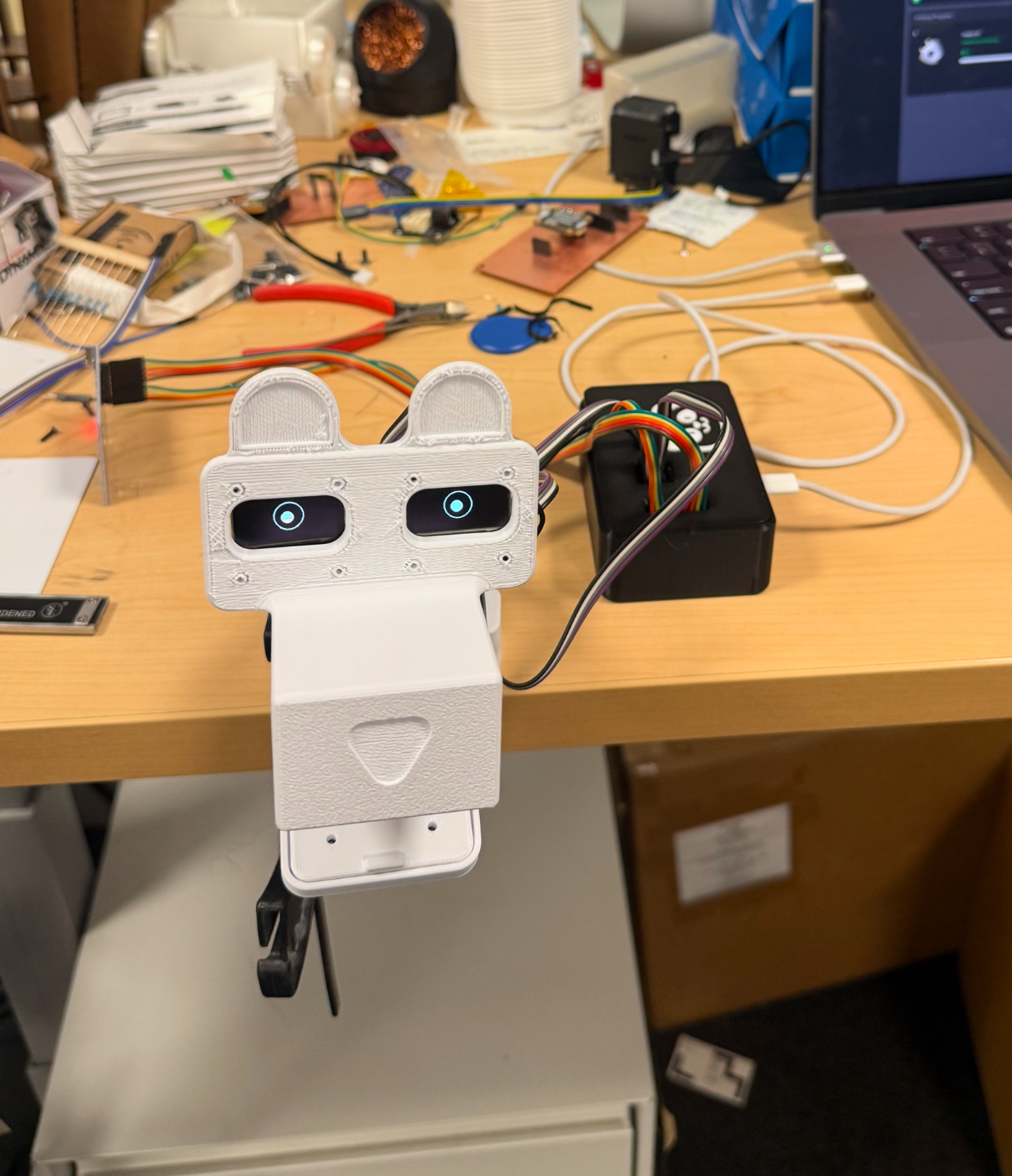
Simple profile and shapes won't create a cute panda head so we need to move onto sculpting in order to get something that is more natural in shape.
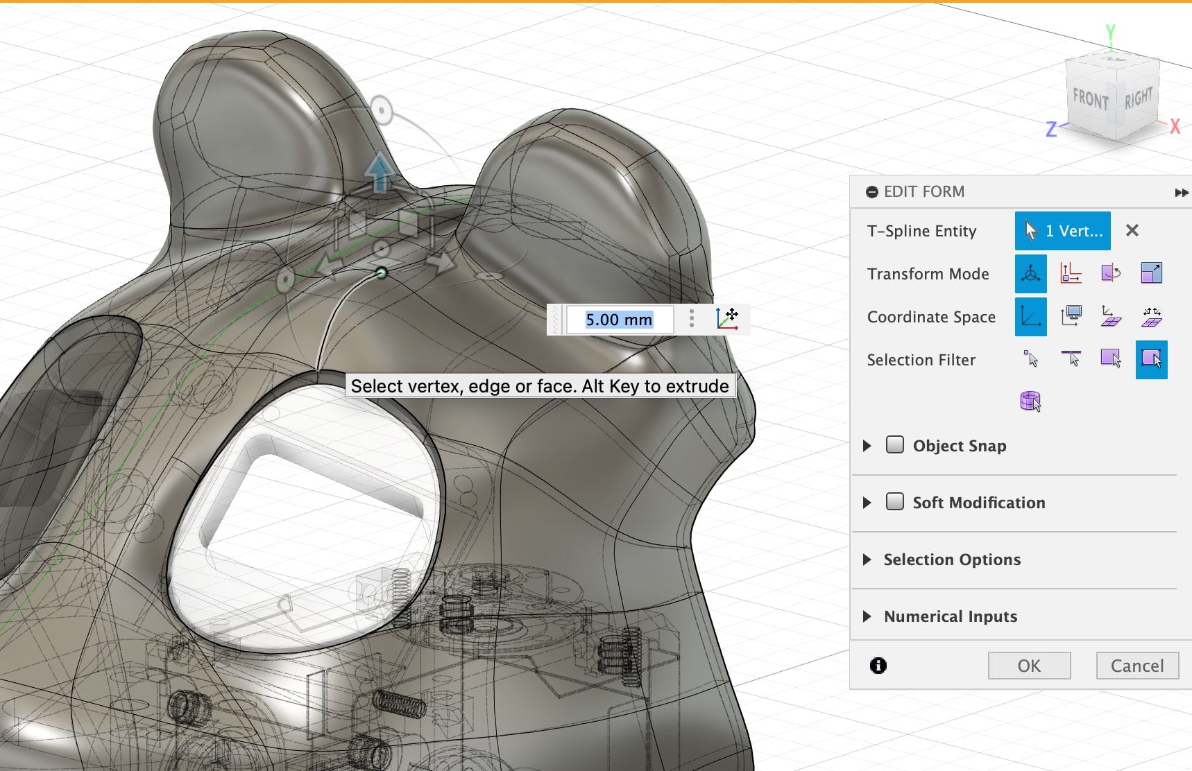
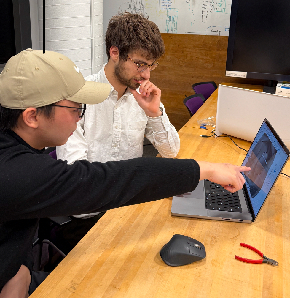
Thank you Homer Su (CS visiting student) for helping me with fusion's sculpting tool so I could make the panda head less scary.
Looks way better now!
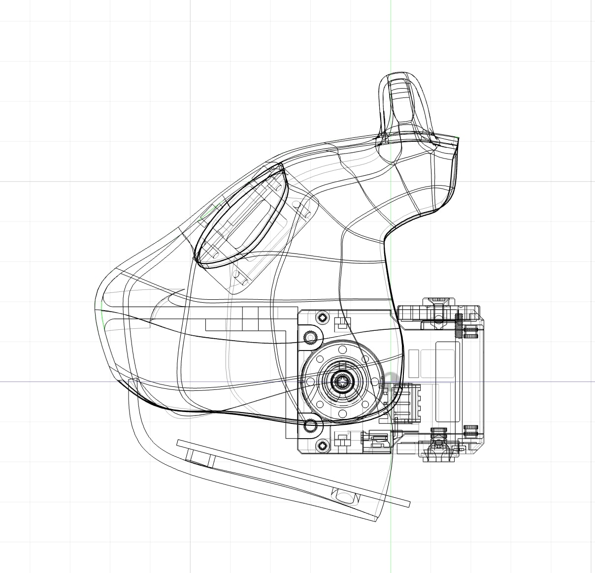
Don't Forget Subtractive!
The panda that is meant to be an urban robot for moving packages around needs a package. This was the perfect opportunity to laser cut some cardboard to make a package
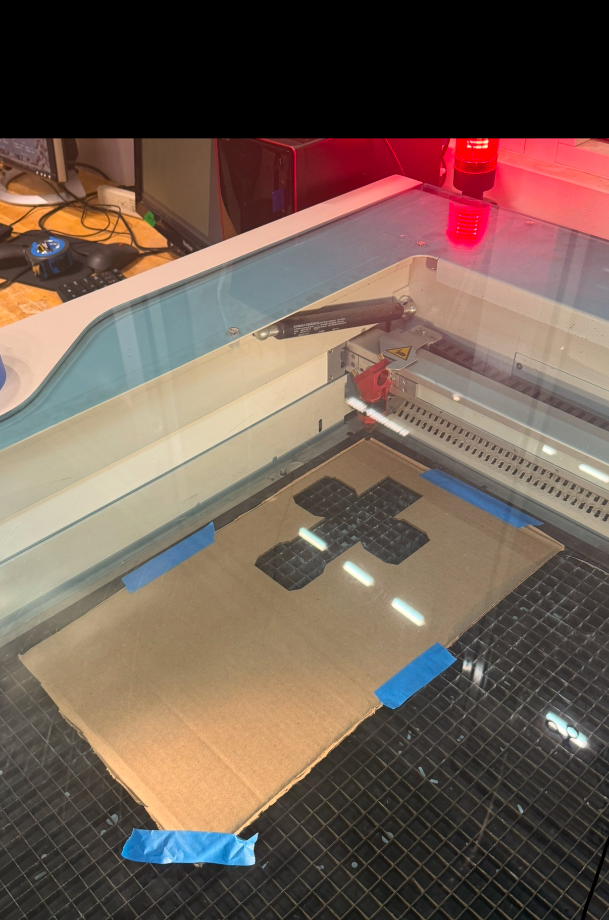
Just look at this nice little box.
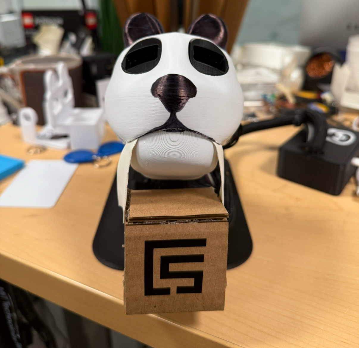
PANDA Grasper
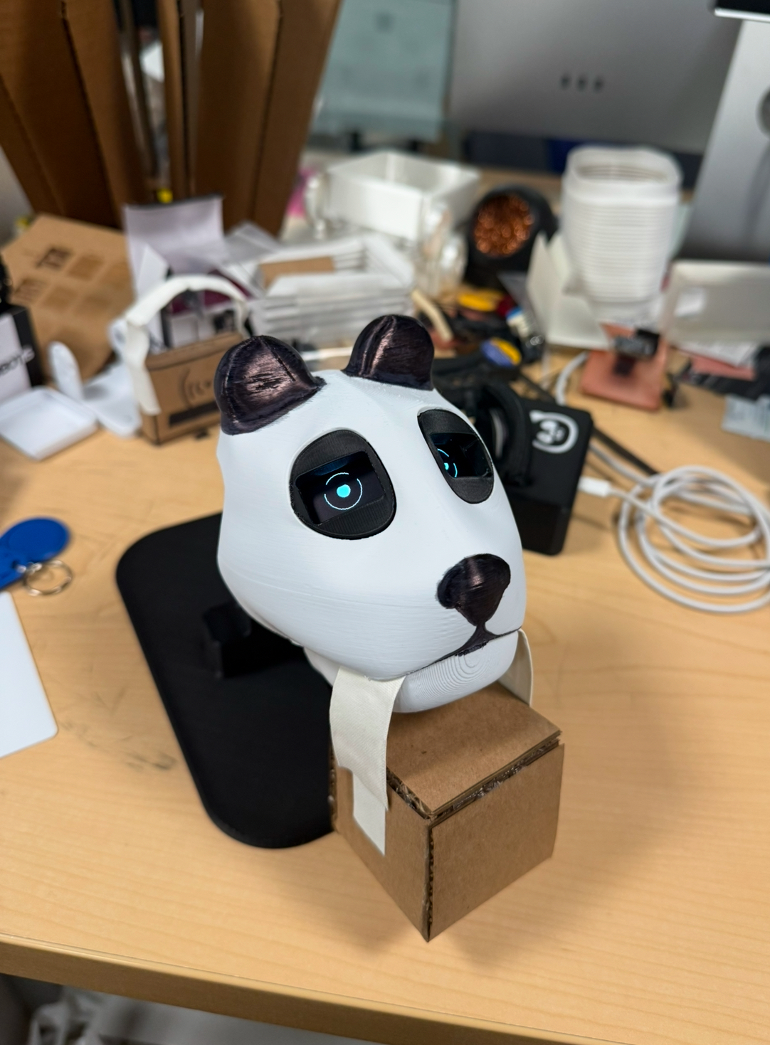
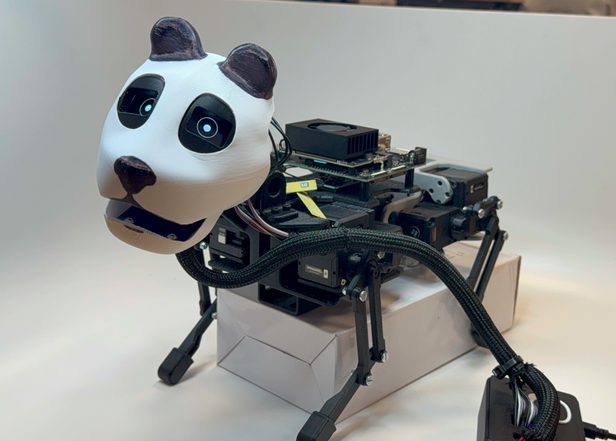
The head fits pretty nicely on the body!
RFID Package Detection Video
I used the tkinter python library to make a basic user interface that displayed address info associated with each RFID tag. The UI also controlled the motor angles of the head.
What questions were answered
This final project helped answer what would a interactable panda package delivery robot look like :) It also anwered what challenges are ahead of a robot like this: sensing, precise control, and many other robotics problems that will need to be overcome if we are going to build delivery robot that is interactable.
How was it evaluated
The system was evaluated by seeing if it could properly open the jaw automatically and display package information. The system was also controlled by the python interface that controlled the joint angles.
What are the implications
The panda grasping mechanisim will be a helpful tool in designing a robot that can interact with people as a last mile delivery assistant. Robots that will perform deliveries need to have good interaction interfaces and this final project is a good start. This project will also be mounted on our quadruped robot which will allow us to understand its limitations and how it can be improved.
Reflections
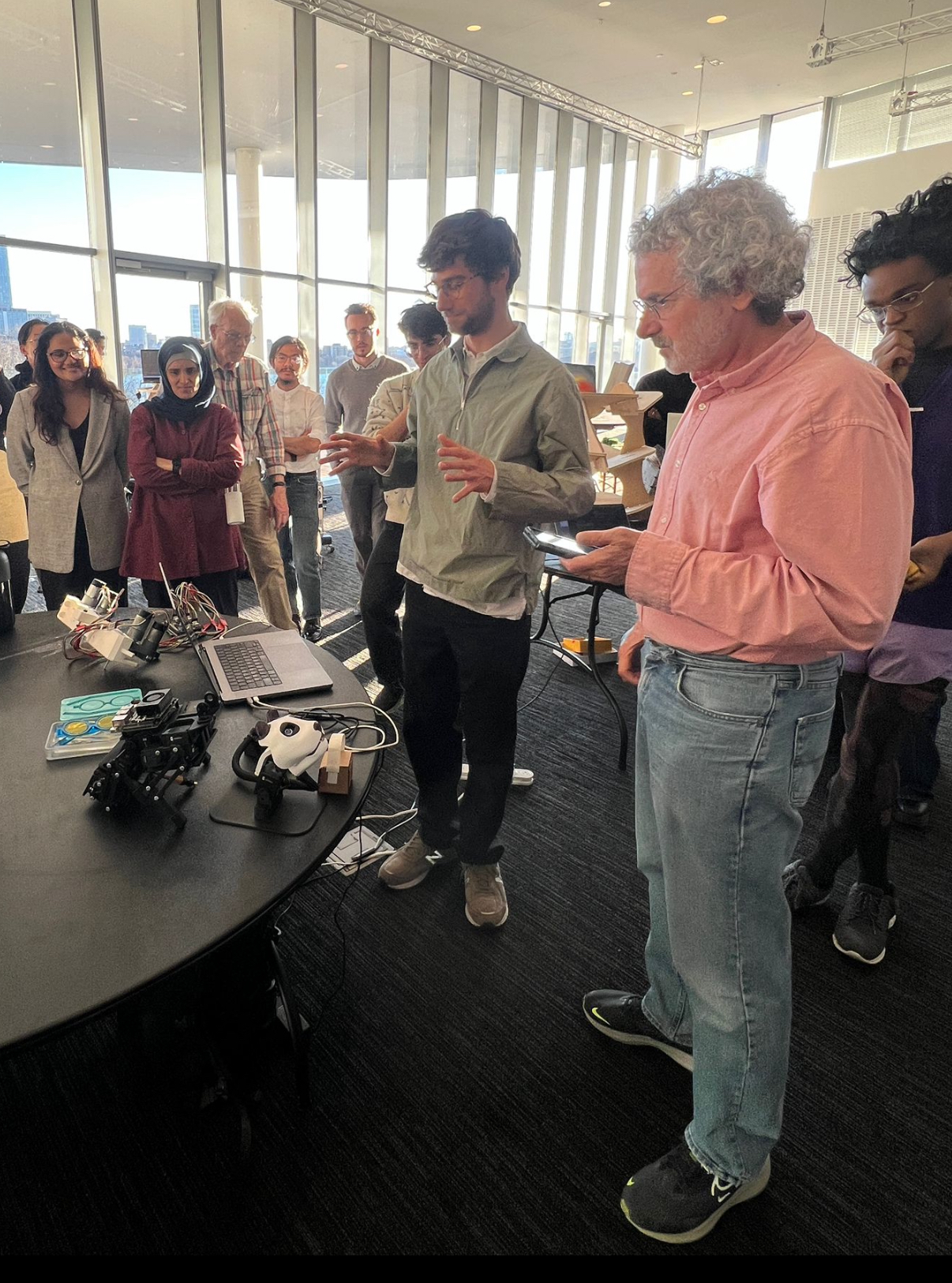
The demo went perfectly! HTMAA is a fantastic course and I am sad that it is over. I want to give a big thanks to Neil, Quentin, Alfonso, Jake, Alex, Miana, Marcello, and all the other TAs that made this class so special.
Project Data
CAD Downloads: case, head, neck, base
User Interface and Servo Control Program
import serial
import tkinter as tk
from tkinter import messagebox
from dynamixel_sdk import *  # Uses Dynamixel SDK library
import threading
import time

# ----- RFID Configuration -----
RFID_PORT = "/dev/tty.usbmodem1101"  # Replace with RFID serial port
BAUDRATE_RFID = 115200

# ----- Motor Configuration -----
SERVO_PORT = "/dev/tty.usbserial-FT9HDAWY"  # Replace with Dynamixel serial port
BAUDRATE_SERVO = 57600
PROTOCOL_VERSION = 2.0
ADDR_TORQUE_ENABLE = 64
ADDR_GOAL_POSITION = 116
ADDR_PRESENT_POSITION = 132
TORQUE_ENABLE = 1
TORQUE_DISABLE = 0
DXL_IDS = [15, 16, 17, 18]  # Motor 19 removed

# Dynamixel joint limits
JOINT_LIMITS = {motor_id: {"min": -45, "max": 45} for motor_id in DXL_IDS}

# Conversion functions
def degrees_to_dxl_units(degrees):
    return max(0, min(4095, int((degrees / 360) * 4095)))

def dxl_units_to_degrees(units):
    return (units / 4095) * 360

# ----- Main GUI and Logic -----
class RobotControlApp:
    def __init__(self, root):
        self.root = root
        self.root.title("RFID and Robot Control")
        self.root.geometry("500x550")

        # RFID Labels
        tk.Label(root, text="RFID Package Recognition", font=("Arial", 16)).pack(pady=5)
        self.label_name = tk.Label(root, text="Name: ", font=("Arial", 12))
        self.label_name.pack(pady=2)
        self.label_address = tk.Label(root, text="Address: ", font=("Arial", 12))
        self.label_address.pack(pady=2)
        self.label_weight = tk.Label(root, text="Weight: ", font=("Arial", 12))
        self.label_weight.pack(pady=2)

        # Motor Control UI
        tk.Label(root, text="Motor Control", font=("Arial", 16)).pack(pady=10)
        self.motor_id_entry = tk.Entry(root, width=10)
        self.motor_id_entry.pack(pady=2)
        self.motor_id_entry.insert(0, "Motor ID")

        self.angle_entry = tk.Entry(root, width=10)
        self.angle_entry.pack(pady=2)
        self.angle_entry.insert(0, "Angle (deg)")

        self.set_button = tk.Button(root, text="Set Motor Angle", command=self.set_motor_angle)
        self.set_button.pack(pady=5)

        self.close_mouth_button = tk.Button(root, text="Close Mouth", command=self.close_mouth)
        self.close_mouth_button.pack(pady=5)

        self.position_text = tk.Text(root, height=10, width=40)
        self.position_text.pack(pady=5)

        # Start RFID thread
        self.zero_positions = {}
        threading.Thread(target=self.read_rfid, daemon=True).start()

        # Initialize servo control
        self.init_servos()

    def read_rfid(self):
        try:
            rfid_ser = serial.Serial(RFID_PORT, BAUDRATE_RFID)
            while True:
                if rfid_ser.in_waiting > 0:
                    uid = rfid_ser.readline().decode().strip()
                    data = rfid_map.get(uid, {"name": "Unknown", "address": "N/A", "weight": "N/A"})
                    self.label_name.config(text=f"Name: {data['name']}")
                    self.label_address.config(text=f"Address: {data['address']}")
                    self.label_weight.config(text=f"Weight: {data['weight']}")

                    # Command motor 17 to +20 degrees
                    self.move_motor_to_angle(17, 20)
        except serial.SerialException:
            messagebox.showerror("Error", "RFID serial port issue.")

    def init_servos(self):
        self.port_handler = PortHandler(SERVO_PORT)
        self.packet_handler = PacketHandler(PROTOCOL_VERSION)
        if not self.port_handler.openPort() or not self.port_handler.setBaudRate(BAUDRATE_SERVO):
            messagebox.showerror("Error", "Failed to initialize Dynamixel connection.")
            exit()

        # Enable torque and zero positions
        for motor_id in DXL_IDS:
            self.packet_handler.write1ByteTxRx(self.port_handler, motor_id, ADDR_TORQUE_ENABLE, TORQUE_ENABLE)
            position, _, _ = self.packet_handler.read4ByteTxRx(self.port_handler, motor_id, ADDR_PRESENT_POSITION)
            self.zero_positions[motor_id] = position
        print("Motors initialized and zeroed.")

    def set_motor_angle(self):
        try:
            motor_id = int(self.motor_id_entry.get())
            desired_angle = float(self.angle_entry.get())

            if motor_id not in DXL_IDS:
                messagebox.showerror("Error", "Invalid Motor ID.")
                return

            limits = JOINT_LIMITS[motor_id]
            if not (limits["min"] <= desired_angle <= limits["max"]):
                messagebox.showerror("Error", f"Angle out of range: {limits['min']} to {limits['max']} degrees.")
                return

            # Compute position relative to zero
            self.move_motor_to_angle(motor_id, desired_angle)
            threading.Timer(0.75, self.update_motor_positions).start()

        except ValueError:
            messagebox.showerror("Error", "Enter valid Motor ID and Angle.")

    def move_motor_to_angle(self, motor_id, angle):
        zero_position = self.zero_positions[motor_id]
        desired_position = zero_position + degrees_to_dxl_units(angle)
        self.packet_handler.write4ByteTxRx(self.port_handler, motor_id, ADDR_GOAL_POSITION, desired_position)
        print(f"Motor {motor_id} set to {angle} degrees relative to zero.")

    def close_mouth(self):
        self.move_motor_to_angle(17, 0)  # Return motor 17 to its zero position
        threading.Timer(0.75, self.update_motor_positions).start()
        print("Motor 17 returned to zero (mouth closed).")

    def update_motor_positions(self):
        self.position_text.delete("1.0", tk.END)
        for motor_id in DXL_IDS:
            position, _, _ = self.packet_handler.read4ByteTxRx(self.port_handler, motor_id, ADDR_PRESENT_POSITION)
            relative_position = dxl_units_to_degrees(position - self.zero_positions[motor_id])
            self.position_text.insert(tk.END, f"Motor {motor_id}: {relative_position:.2f} degrees\n")

# RFID Data Map
rfid_map = {
    "49:b4:1b:2f": {"name": "Jonny Cohen", "address": "75 Amherst St, Cambridge, MA", "weight": "1kg"},
    "93:da:46:da": {"name": "Neil Gershenfeld", "address": "Center For Bits and Atoms, Cambridge, MA", "weight": "5kg"},
}

# ----- Run the Application -----
if __name__ == "__main__":
    root = tk.Tk()
    app = RobotControlApp(root)
    root.mainloop()
Embedded Code
#include MFRC522.h
#include SPI.h
#include Wire.h
#include Adafruit_GFX.h
#include Adafruit_SSD1306.h
#include math.h

#define CS_PIN 17   // GPIO17 for Chip Select
#define RST_PIN -1  // Leave RST unconnected

#define SCREEN_WIDTH 128
#define SCREEN_HEIGHT 64

Adafruit_SSD1306 display(SCREEN_WIDTH, SCREEN_HEIGHT, &Wire, -1);

MFRC522 mfrc522(CS_PIN, RST_PIN);

// Eye animation parameters
int eyeX = SCREEN_WIDTH / 2;  // X position of the eye
int eyeY = SCREEN_HEIGHT / 2; // Y position of the eye
int eyeRadius = 30;           // Radius of the eye
int pupilRadius = 10;         // Radius of the pupil
int blinkState = 0;           // Blink state (0 = open, 1 = closed)

void setup() {
  Serial.begin(115200);
  while (!Serial);

  SPI.begin(); // Initialize SPI bus
  mfrc522.PCD_Init(); // Initialize MFRC522 reader

  Serial.println(F("RC522 RFID Reader Initialized."));

  if (!display.begin(SSD1306_SWITCHCAPVCC, 0x3C)) {
    while (1); // Hang if the display fails to initialize
  }

  display.clearDisplay();
  display.setTextSize(1);
  display.setTextColor(SSD1306_WHITE);

  displayFlippedText("Initializing...", 0, 0);
  delay(2000);
}

void loop() {
  // Eye animation logic
  animateEye();

  // RFID scanning logic
  if (mfrc522.PICC_IsNewCardPresent() && mfrc522.PICC_ReadCardSerial()) {
    String uid = "";
    for (byte i = 0; i < mfrc522.uid.size; i++) {
      uid += String(mfrc522.uid.uidByte[i], HEX);
      if (i < mfrc522.uid.size - 1) {
        uid += ":";
      }
    }

    Serial.println(uid);
    displayFlippedText("Package Detected", 0, 0); // Display flipped text
    delay(2000);
  }
}

void animateEye() {
  display.clearDisplay();

  // Draw the eye outline
  drawFlippedCircle(eyeX, eyeY, eyeRadius);

  // Blink logic
  if (blinkState == 1) {
    // Eye closed (draw a line instead of a pupil)
    drawFlippedLine(eyeX - eyeRadius, eyeY, eyeX + eyeRadius, eyeY);
  } else {
    // Eye open, draw the pupil
    int pupilX = eyeX + random(-5, 5); // Slight random movement
    int pupilY = eyeY + random(-3, 3); // Slight random movement
    drawFlippedFilledCircle(pupilX, pupilY, pupilRadius);
  }

  display.display();
  delay(300);

  // Change blink state occasionally
  if (random(0, 10) > 8) {
    blinkState = 1 - blinkState; // Toggle blink state
  }
}

void displayFlippedText(const char *message, int x, int y) {
  display.clearDisplay();
  display.setCursor(x, SCREEN_HEIGHT - y - 8); // Flip vertically
  display.print(message);
  display.display();
}

void drawFlippedCircle(int x, int y, int radius) {
  display.drawCircle(x, SCREEN_HEIGHT - y, radius, SSD1306_WHITE); // Flip Y-axis
}

void drawFlippedFilledCircle(int x, int y, int radius) {
  display.fillCircle(x, SCREEN_HEIGHT - y, radius, SSD1306_WHITE); // Flip Y-axis
}

void drawFlippedLine(int x0, int y0, int x1, int y1) {
  display.drawLine(x0, SCREEN_HEIGHT - y0, x1, SCREEN_HEIGHT - y1, SSD1306_WHITE);
}
ChatGPT 4o was used for coding!