Overview
The first part of this week was about learning how to document, use git, and build html websites. The second part was on how to use computer controlled cutters including the viynl cutter and the CO2 laser cutter. I have never used HTML before so the website is pretty basic now but hopefully it will get more advanced as I learn more throughout the semester.
Tools Used
Laser Cutter, Viynl Cutter, GIT, HTML (basic formatting generated by ChatGPT 4o then edited by me)
Group Assignment
The aim of the group assignment was to work together to understand basic joints for connect flat parts together. We measured the laser kerf (diameter that the beam removes material). We also tested various clearence and interference fits in our joints. The second goal was to characterize the laser cutter on cardboard across an array of powers and speeds.
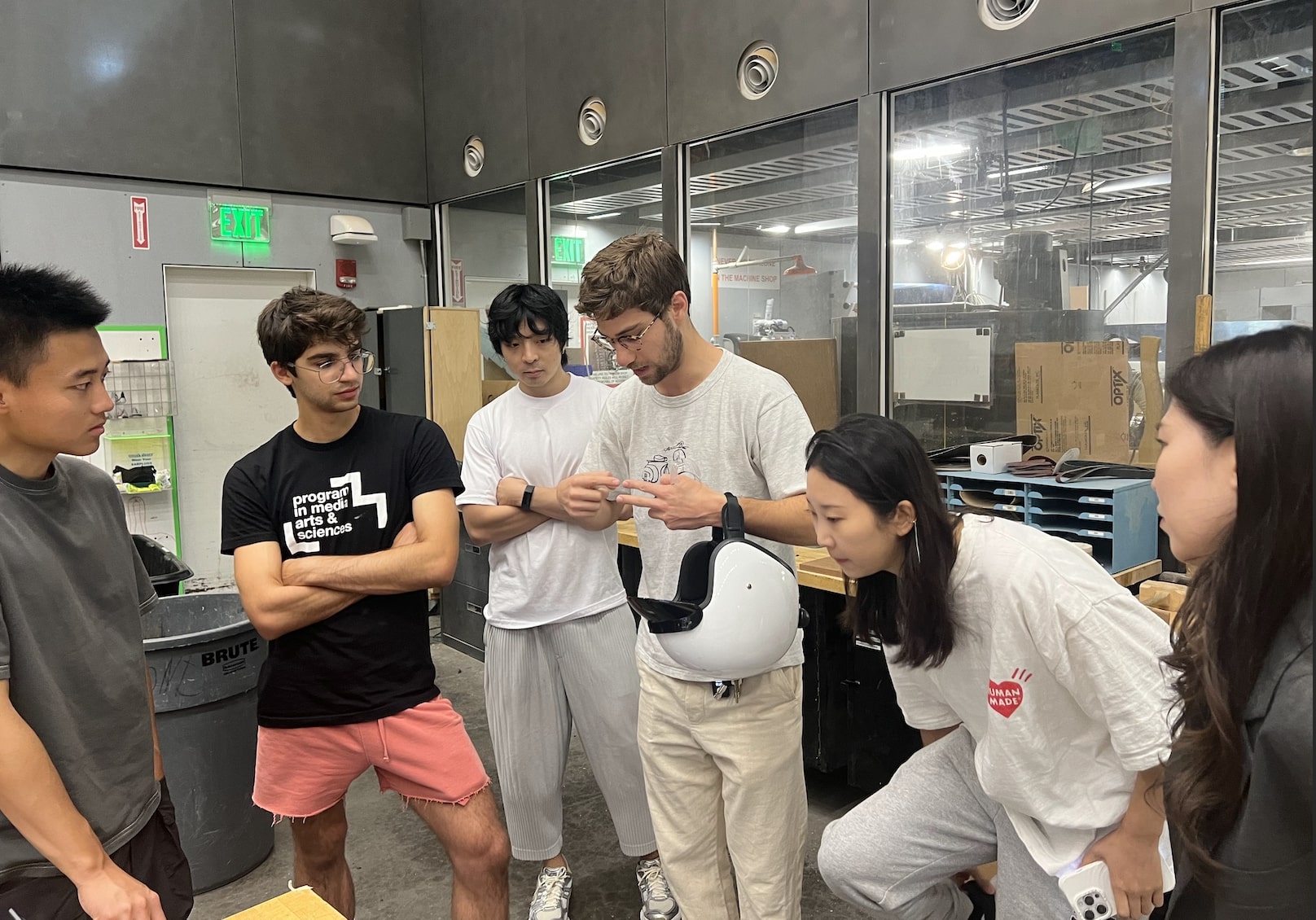
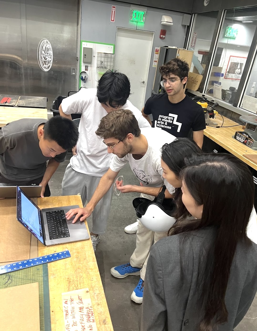
This looks like Jonny should get extra credit for explaining interference fits, right? (Photo Cred Jessica Stringham)
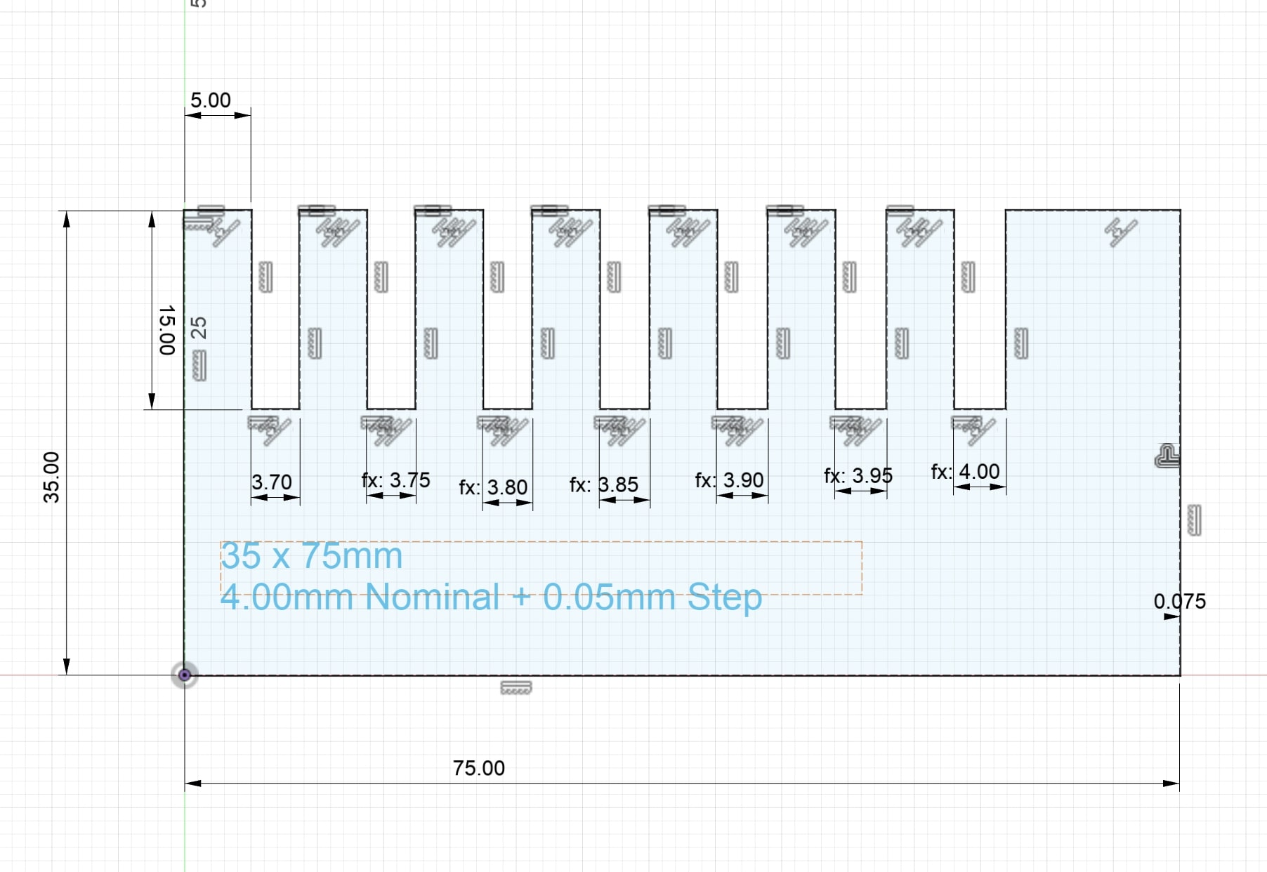
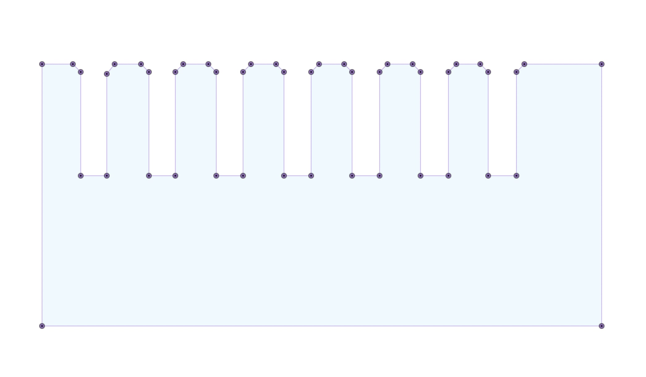
We made combs to test out different inteferences. CAD Link
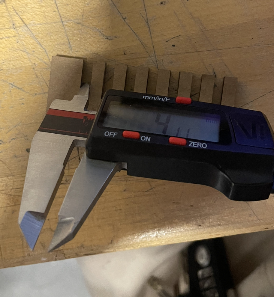
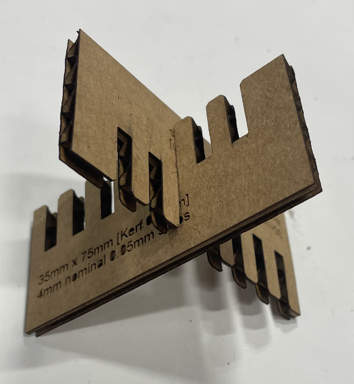
We mismeasured the original kerf by 0.1mm and so we needed to iterate on the comb to try to get the joint to be exactly 4.0mm. The cardboard is very soft and so it is easy to misread the kerf. We found the kerf to be 0.2mm diameter and since the laser toolpath follows the sketch, you need to offset your geometry by kerf/2 or 0.1mm. We also found that the third slot on the comb was ideal for connecting cardboard (3.90mm) which is approximately a 0.1mm interference fit for the press fit joint.
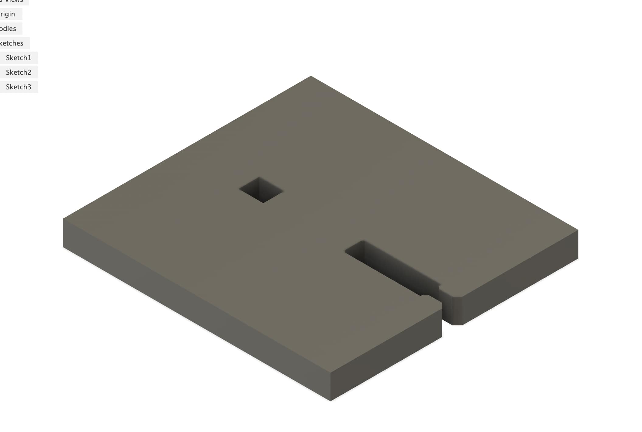
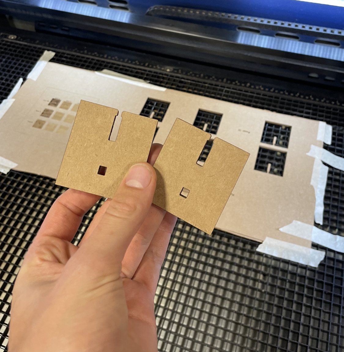
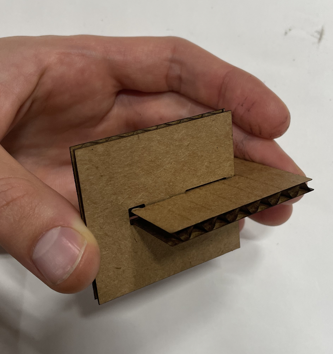
We tested out the snap fit joint for fun. CAD Link
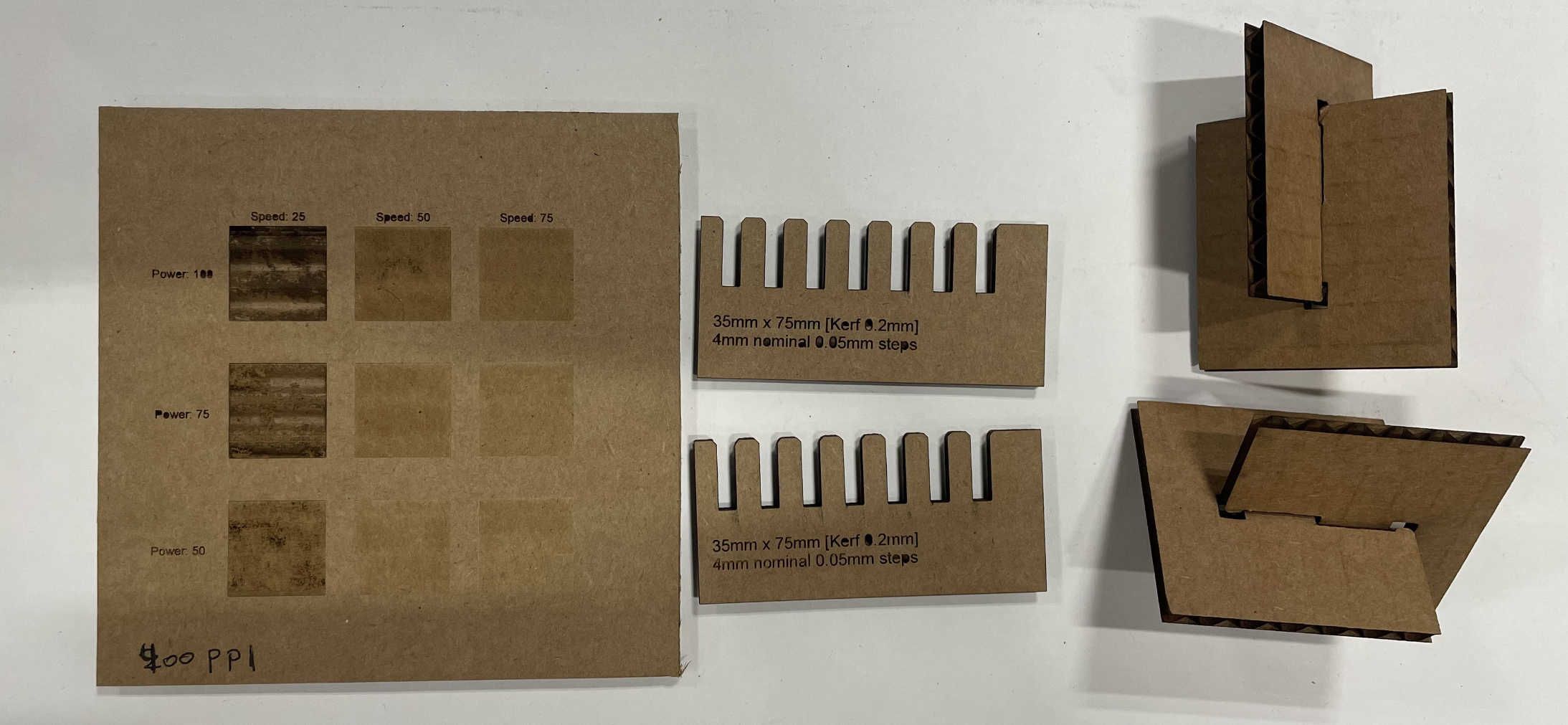
Showing off our final work! Combs, grid of engraving powers, and a snap fit.
Viynl Cutter Assignment
I wanted to make a sticker for my laptop since it currently has no stickers and so I made a city science logo sticker for my laptop.
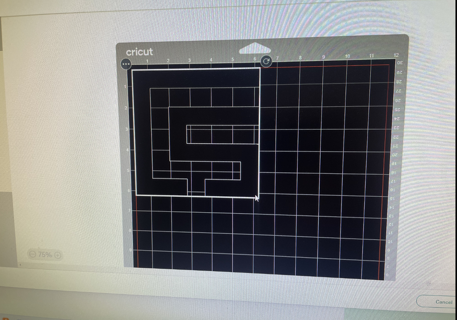
Use a transparent logo from city science to make the sticker
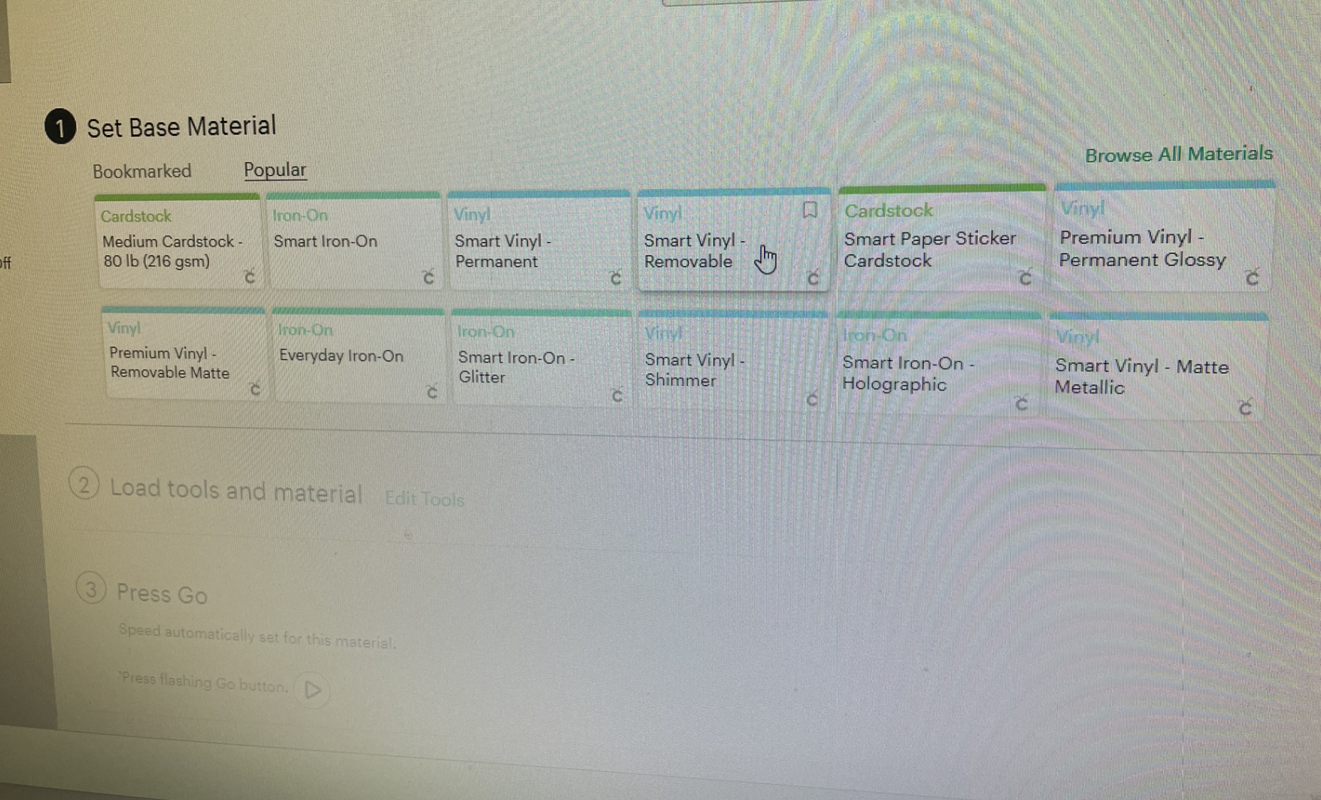
Configure the print
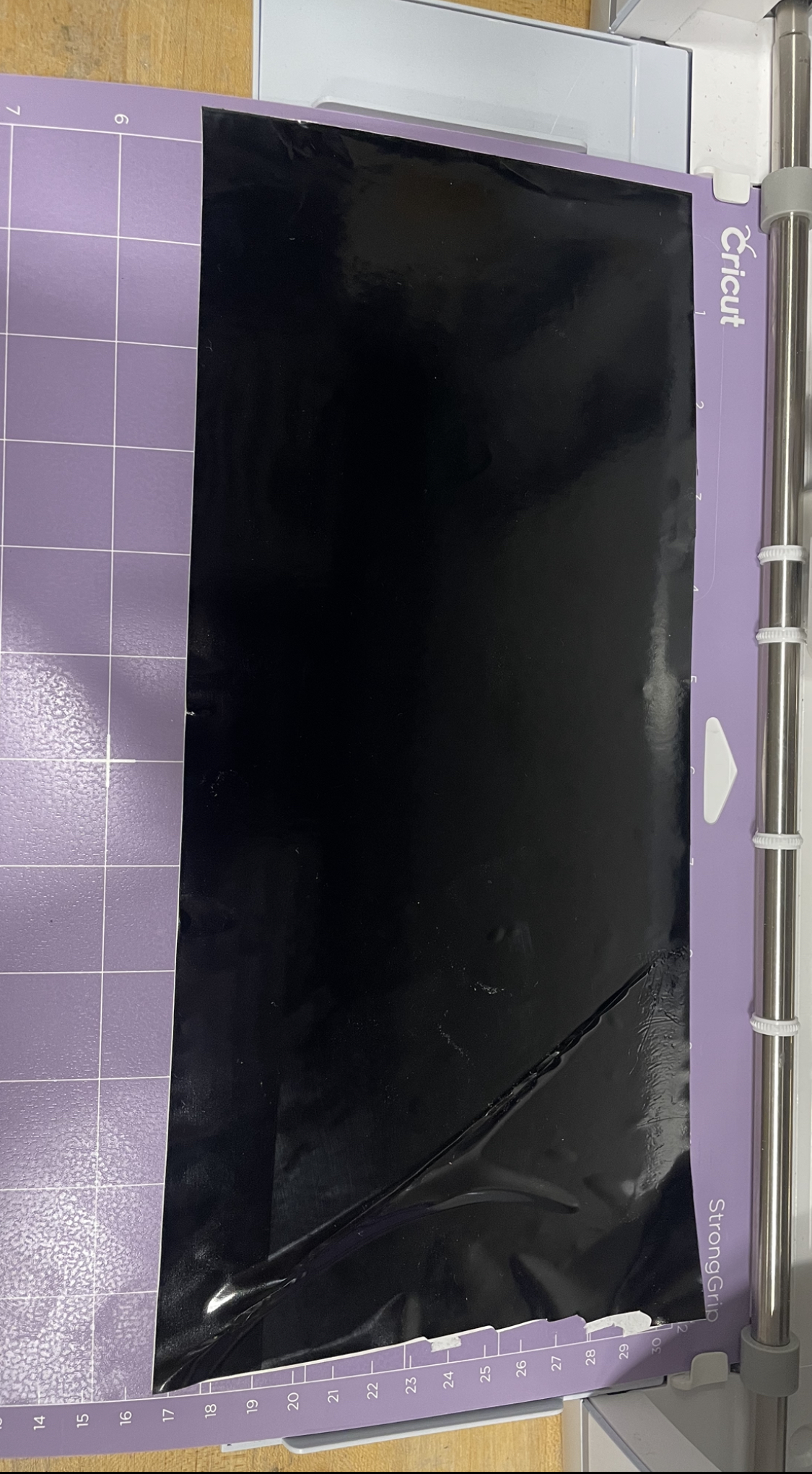
Load up the printer with black viynl for cuting and print!
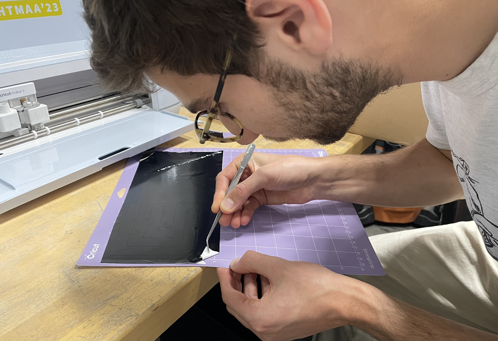
Here I am peeling out the sticker from the backing
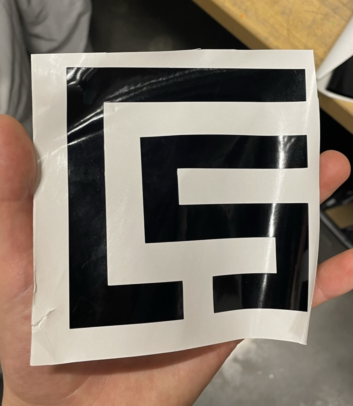
Here is the sticker attached to the backing
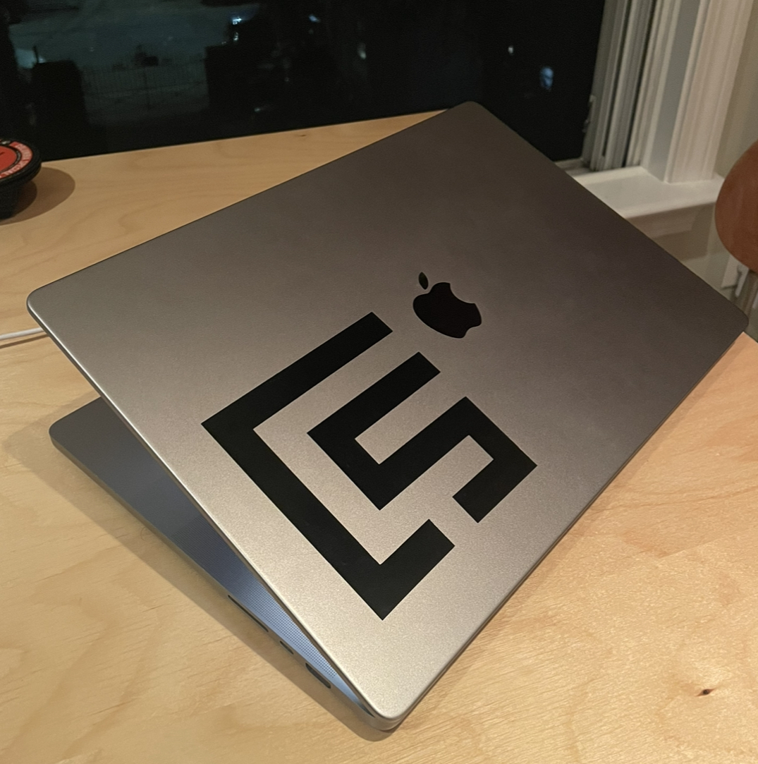
Finished! I now have the largest City Science sticker in my group :-) I am curious to test out making circuits with the viynl cutter since it
Laser Cutter Assignment
For the main assignment "parametric constuction kit" I designed a lamp and built it. We are going to laser cut a "kit" for assembly. I decided to make a lamp..
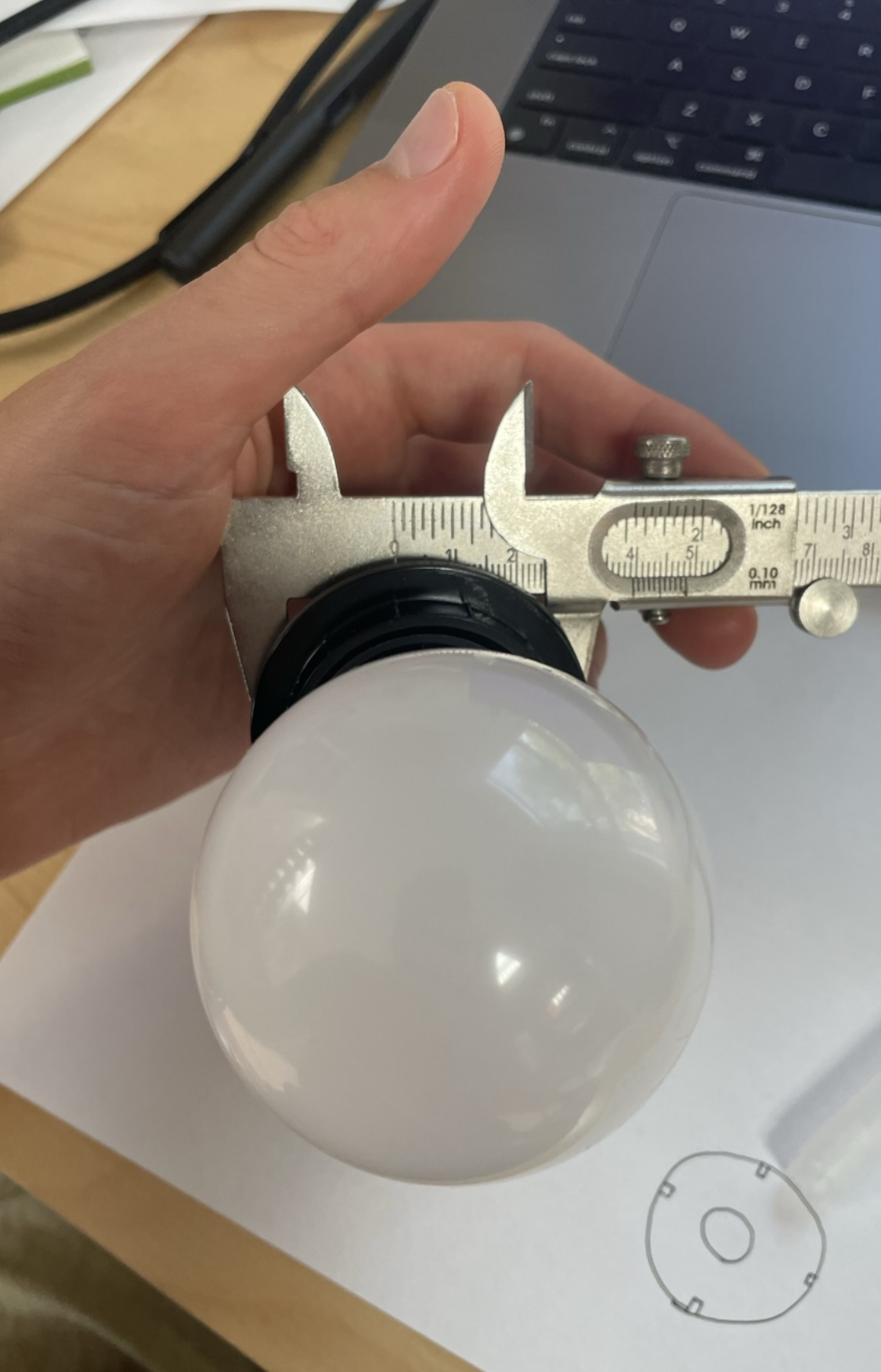
In order for the lamp to work I needed to design it around the light socket I had on hand so I took some measurements
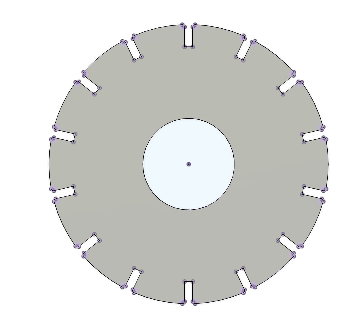
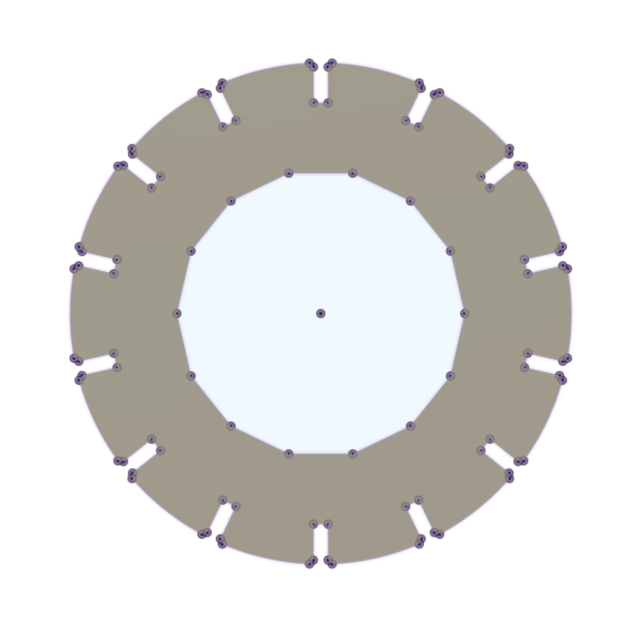
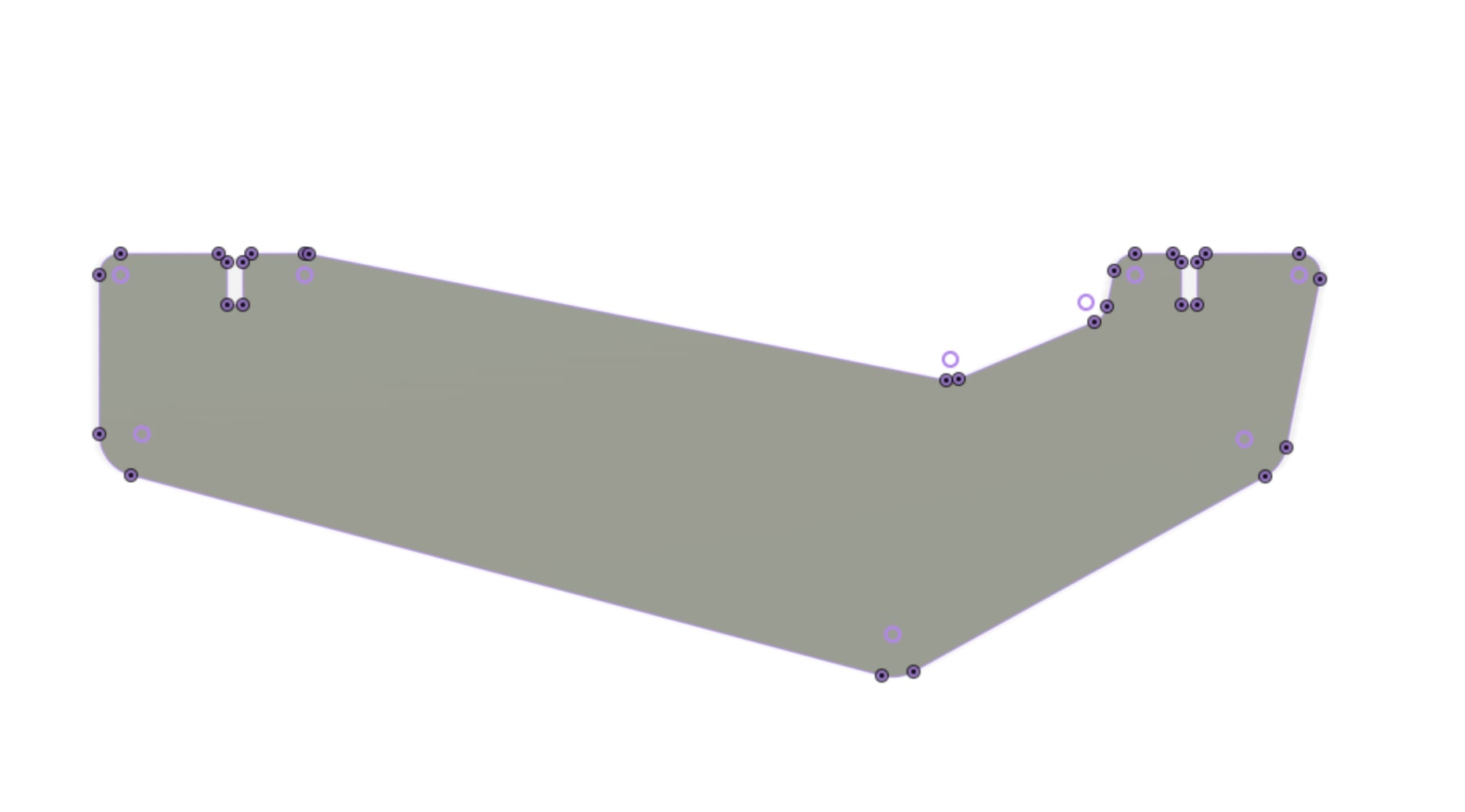
Lamp socket end piece is on the left, and the 14 sides polygon cutout end piece is in the middle and on the right is the part that is repeated 14 times to diffuse the light. I designed the part that interfaces with the lamp socket first since that would drive the design and was my only other constraint aside from cardboard. The two end pieces are axially symetric so I used circular pattern for the slot cuts etc. Link to sketches
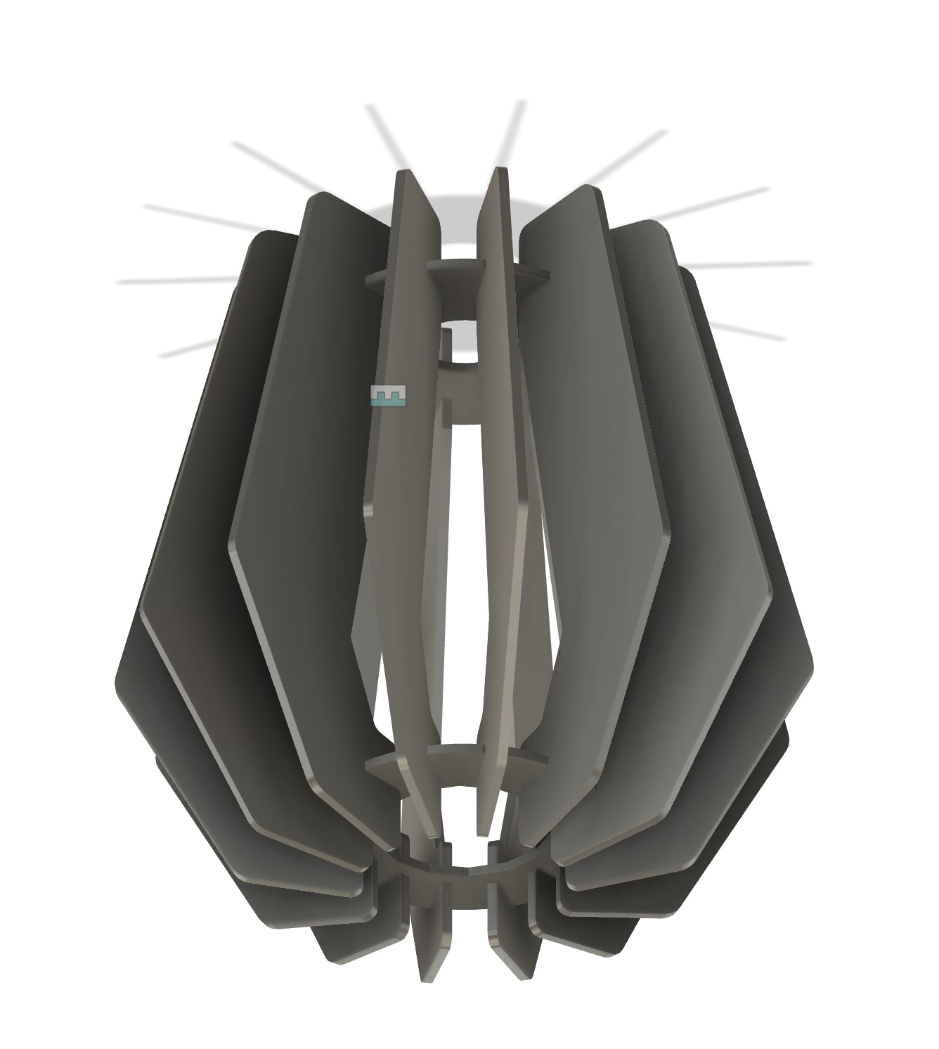
I made an assembly in fusion to see how the actual lamp will look. I looped back between the components and assembly a few times to get it to look the way I wanted it to.
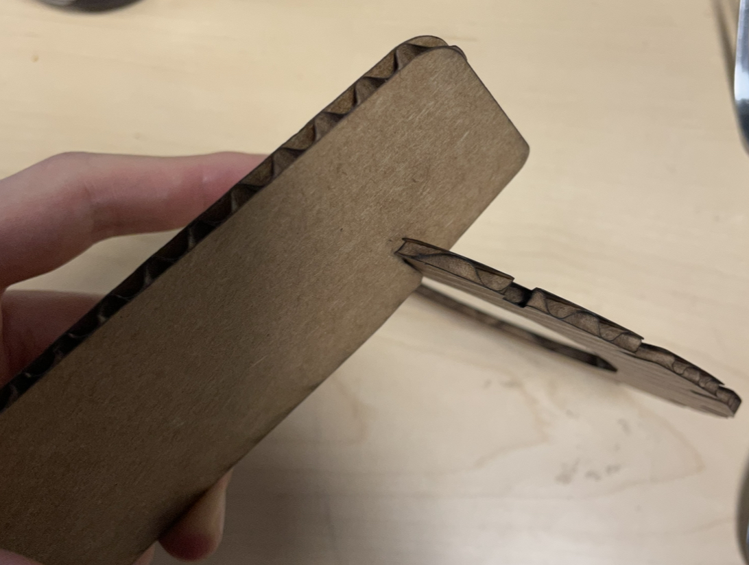
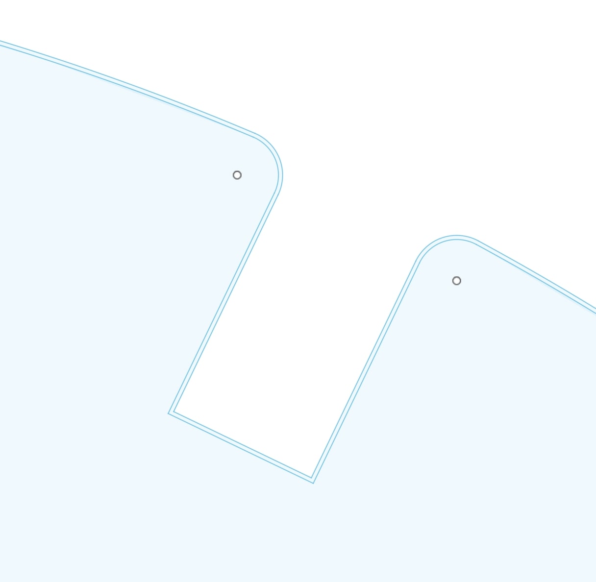
On the first pass at cutting, I did a joint test fit and there was too much slop which was strange. I did another attempt at cutting and realized that the laser was actually cutting along the non-offset outline. It appears that fusion will export a linked original sketch profile even if the offset was generated in another sketch plane without the original profile projection. This is certainly frustrating since the original profile does not even show up in the sketch (only the desired offset profile) inside the sketch prior to export. I have encountered many of this little things when using fusion.
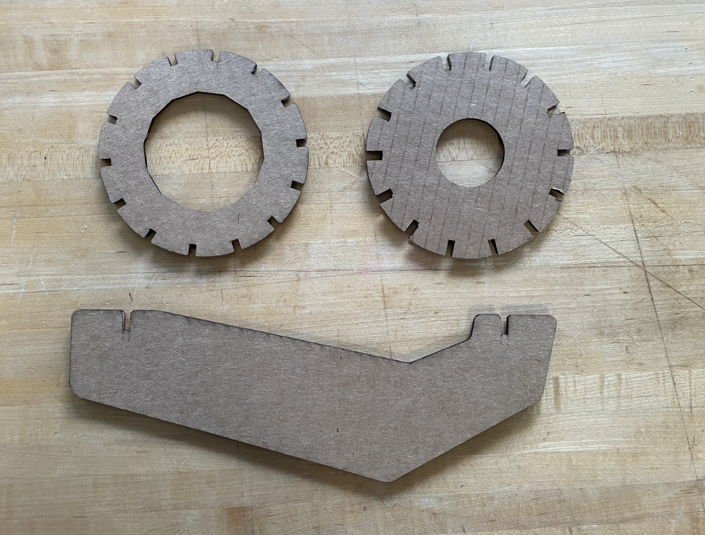
Here are the basic three components of the lamp. Quite simple when you lay it out (can you see the smiling face?).
Final Results!
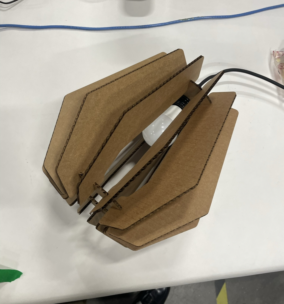
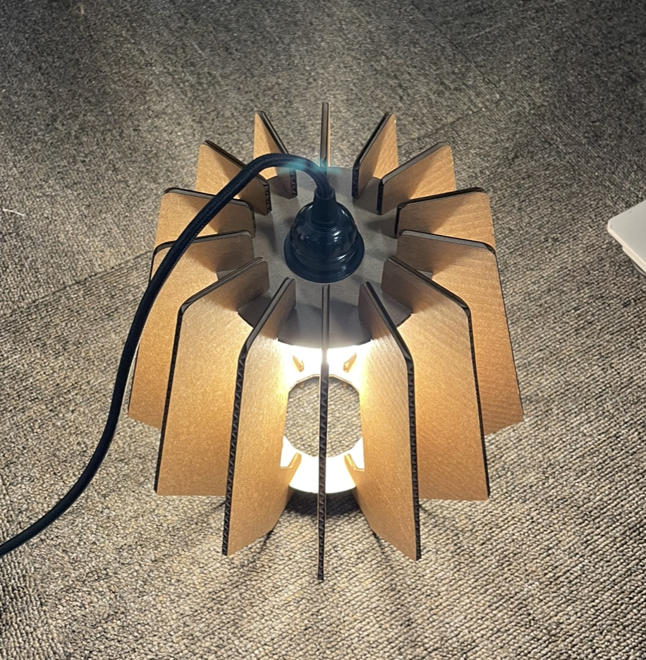
And...a lamp! I already wish I made it probably twice the size but then it would be hard to use it as a table lamp. The lamp would also probably look a lot better if it has something to diffuse the light (CAD Link )