HTMAA 2024 - Jonathan Cohen
For the group assignment Quentin led the discussion into various chip architectures (see below), peripherals, adding board support to arduino ide, programming interfaces, debuggers, and how to burn a bootloader.
MCUs Discussed
We discussed the pros and cons of various board and why we would select a specific board for a design. We learned what programming a board looks like and how boards with a usb interface don't need a seperate programmer (i.e. esp32) but simple boards (think: ATtiny etc) need a programmer to be flashed with a JTAG (4 pins) or SWD (2 pins) interface. Some of the devices have amazing built in peripherals like the ESP32 that has wifi inside. Complex micro controllers like the ESP32 expose a subset of their pins in each package and vary across the product line. We also learned about the pinout of a USB A connector (Vbus, D-, D+, GND) and I also learned that USB uses a differential signal. At the end of the session we interacted with the esp32 board with MicroPython over usb.

(image credit: Kye Shimizu)
I will be using Wokwi.com to test out embedded programming on embedded devices.
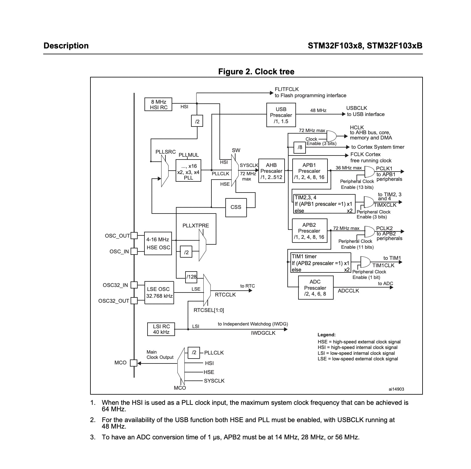
I went through a data sheet! Look at these nice clocks :) I selected the stm32 since I have to use it a bunch in another robotics course using the nucleo family that I am also taking and want to get really good at programming them.

I am going to start with an example with a button and an LED but we will add a stepper motor that will step forward when the button is pressed.
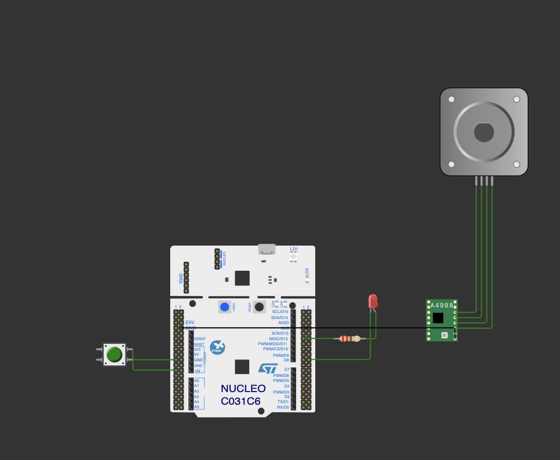
Got the wiring all set up and now it is time to code this!
// HWTMAA WEEK 3 EMBEDDED PROGRAMMING
// Started with LED + button demo on Wokwi
// Define pin for LED and push button
#define LED_PIN PA5        // LED pin
#define BUTTON_PIN PC13    // Button pin
#define stepPin D3         // Step pin for stepper motor
#define dirPin D5          // Direction pin for motor driver
#define enablePin D8       // Enable pin for motor driver

// Variables to count LED states
int ledOnCount = 0;    // Counter for how many times LED has been on
int ledOffCount = 0;   // Counter for how many times LED has been off

// Variables to store the previous state of the LED and button
bool ledState = LOW;      // Initial LED state (off)
bool lastButtonState = HIGH;  // Previous button state (HIGH because of pull-up)

// Stepper motor delay for speed control
int stepDelay = 500;    // Delay in microseconds for step pulses

void setup() {
  // Initialize pin modes
  pinMode(LED_PIN, OUTPUT);          // LED as output
  pinMode(BUTTON_PIN, INPUT_PULLUP); // Button as input with internal pull-up
  pinMode(stepPin, OUTPUT);          // Step pin as output for stepper motor
  pinMode(dirPin, OUTPUT);           // Motor direction pin as output
  pinMode(enablePin, OUTPUT);        // Motor enable pin as output

  // Serial monitor for debugging
  Serial.begin(9600);
}

void loop() {
  // Read the current button state
  bool currentButtonState = digitalRead(BUTTON_PIN);

  // Check if the button was pressed (transition from HIGH to LOW)
  if (currentButtonState == LOW && lastButtonState == HIGH) {
    // Toggle the LED state
    ledState = !ledState;

    // If the LED is turned on
    if (ledState == HIGH) {
      ledOnCount++; // Increment LED on counter
      digitalWrite(dirPin, HIGH);      // Set motor direction
      digitalWrite(enablePin, HIGH);   // Enable motor driver

      Serial.print("LED and Motor ON Count: ");
      Serial.println(ledOnCount);

      // Generate steps manually with delays
      for (int i = 0; i < 10; i++) {  // Run for 1000 steps (or adjust as needed)
        digitalWrite(stepPin, HIGH);    // Set step pin HIGH
        delayMicroseconds(stepDelay);   // Wait for step delay
        digitalWrite(stepPin, LOW);     // Set step pin LOW
        delayMicroseconds(stepDelay);   // Wait for step delay
      }

    }
    // If the LED is turned off
    else {
      ledOffCount++; // Increment LED off counter
      digitalWrite(enablePin, LOW);    // Disable motor driver
      Serial.print("LED and Motor OFF Count: ");
      Serial.println(ledOffCount);
    }

    // Set the LED according to its state
    digitalWrite(LED_PIN, ledState);
  }

  // Save the button state for the next loop cycle
  lastButtonState = currentButtonState;

  // Delay for button debounce (to avoid reading multiple presses quickly)
  delay(50);
}
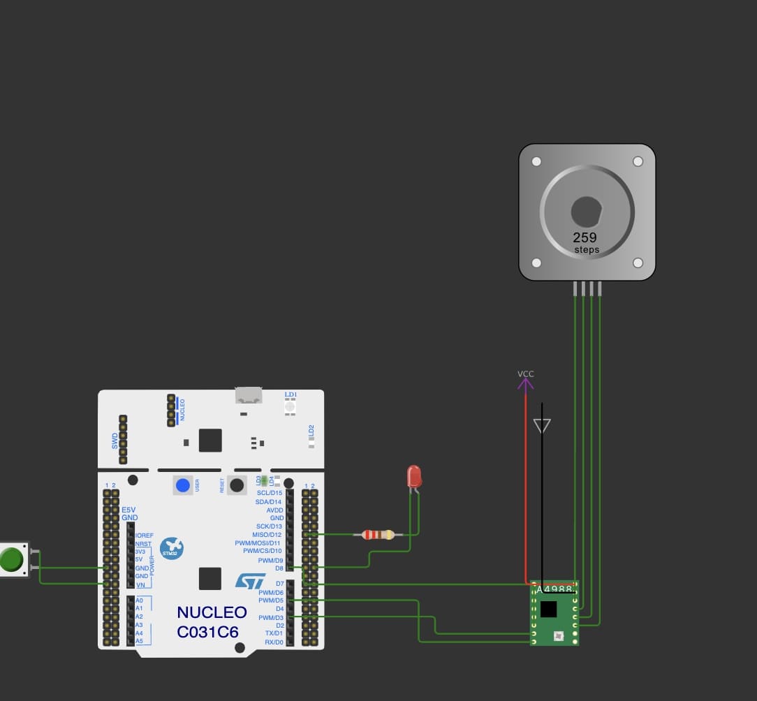
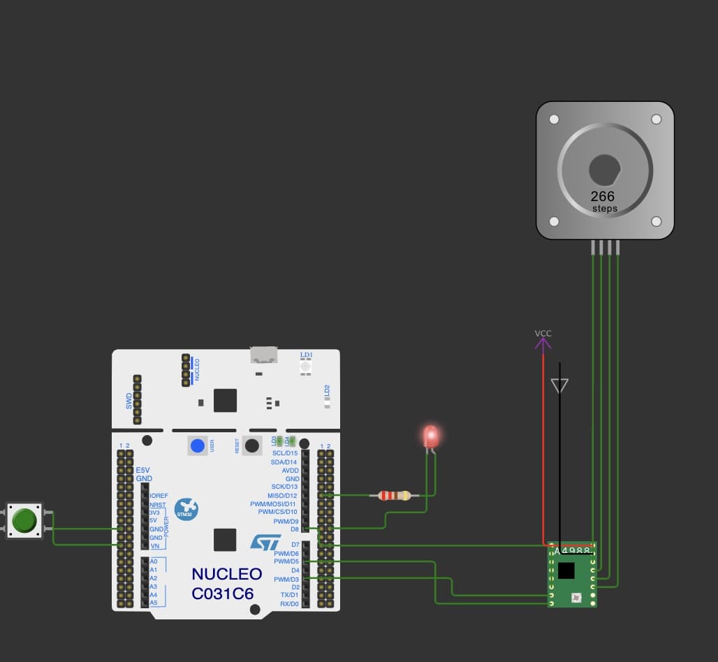
When you press the button the motor steps forward! Yay! The failure here is that I first tried to PWM the step input pin on the motor driver but I could not get it to work. I wonder if I was using the wrong frequency that was far too fast and just read it as HIGH the entire time. Instead we are just using a 500 microsec delay between high and low.

Wowi is cool and easy to use but it has limitations. You can move fast but when it comes to debugging it is less intuitive than having real boards in front of you. I can imagine that wowi is very nice for documentation and also helpful for brainstorming but when it comes to debugging, its quite cumbersome.