PCB Design and Assembly
Diana’s Demonstration of the Roland Monofab SRM-20 and PCB Milling
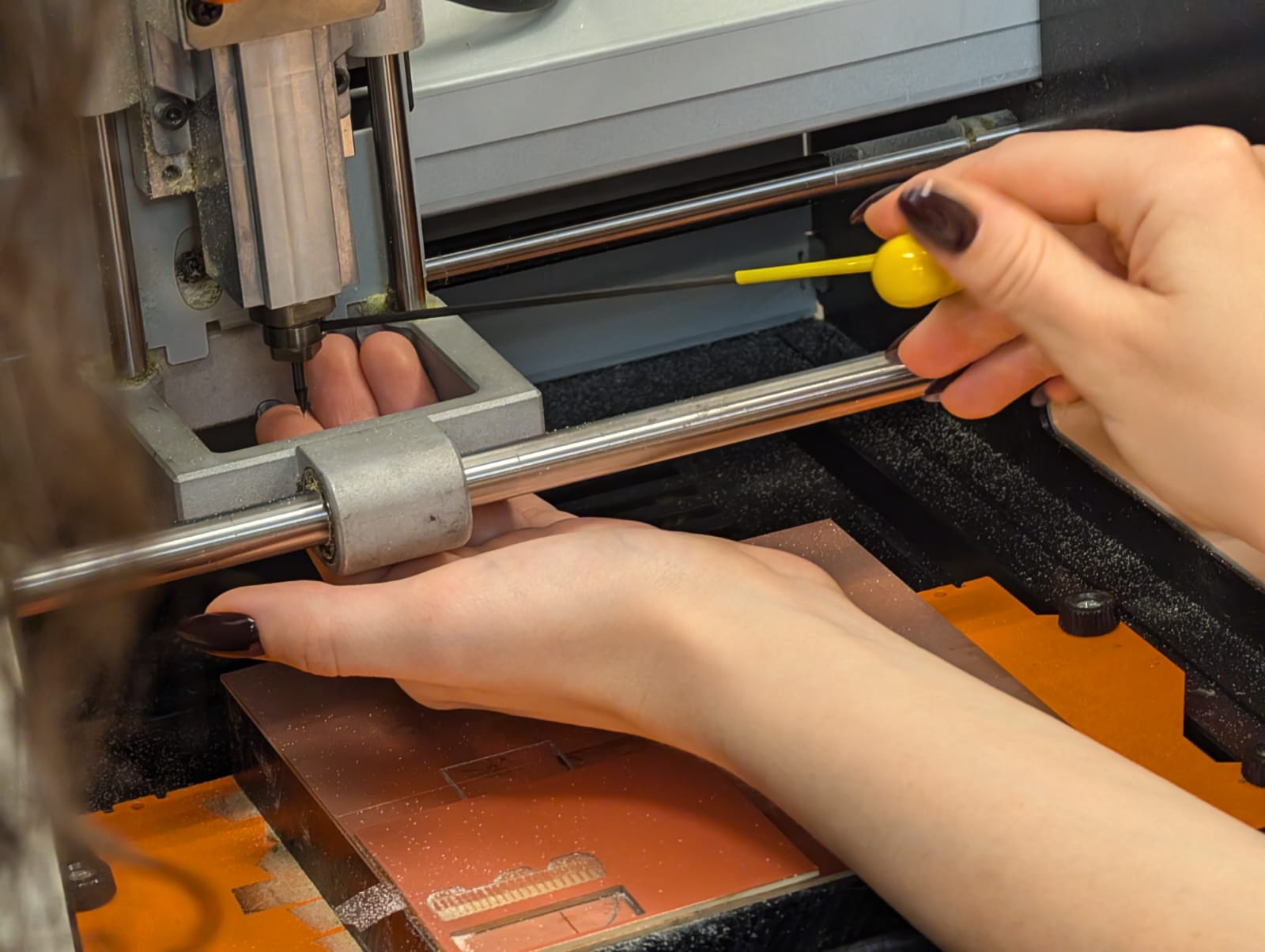
Diana, our TA, began the session by walking us through the operation of the Roland Monofab SRM-20 milling machine, providing a hands-on demonstration on how to set it up for precise PCB production. She started by explaining how to securely fasten the blank copper-clad board onto the milling bed using double-sided tape to prevent movement during the milling process. Diana emphasized the importance of calibrating the end mill bits, showing us how to change the 1/64-inch bit for milling fine traces and the 1/32-inch bit for edge cutting. She guided us through the software interface, detailing how to import the Gerber PNG files and configure the cutting parameters, such as feed rate and spindle speed, to avoid damaging the copper layer. We learned how to set the zero point accurately and run a test pass to ensure alignment before starting the actual milling process.
After milling, Diana explained how to carefully inspect the milled board for defects using a multimeter to check for continuity along the traces and to identify potential shorts between adjacent lines. She also demonstrated how to use soap and water to clean the milled PCB, removing any copper debris and oxidation.

Characterizing the In-House PCB Production Design Rules
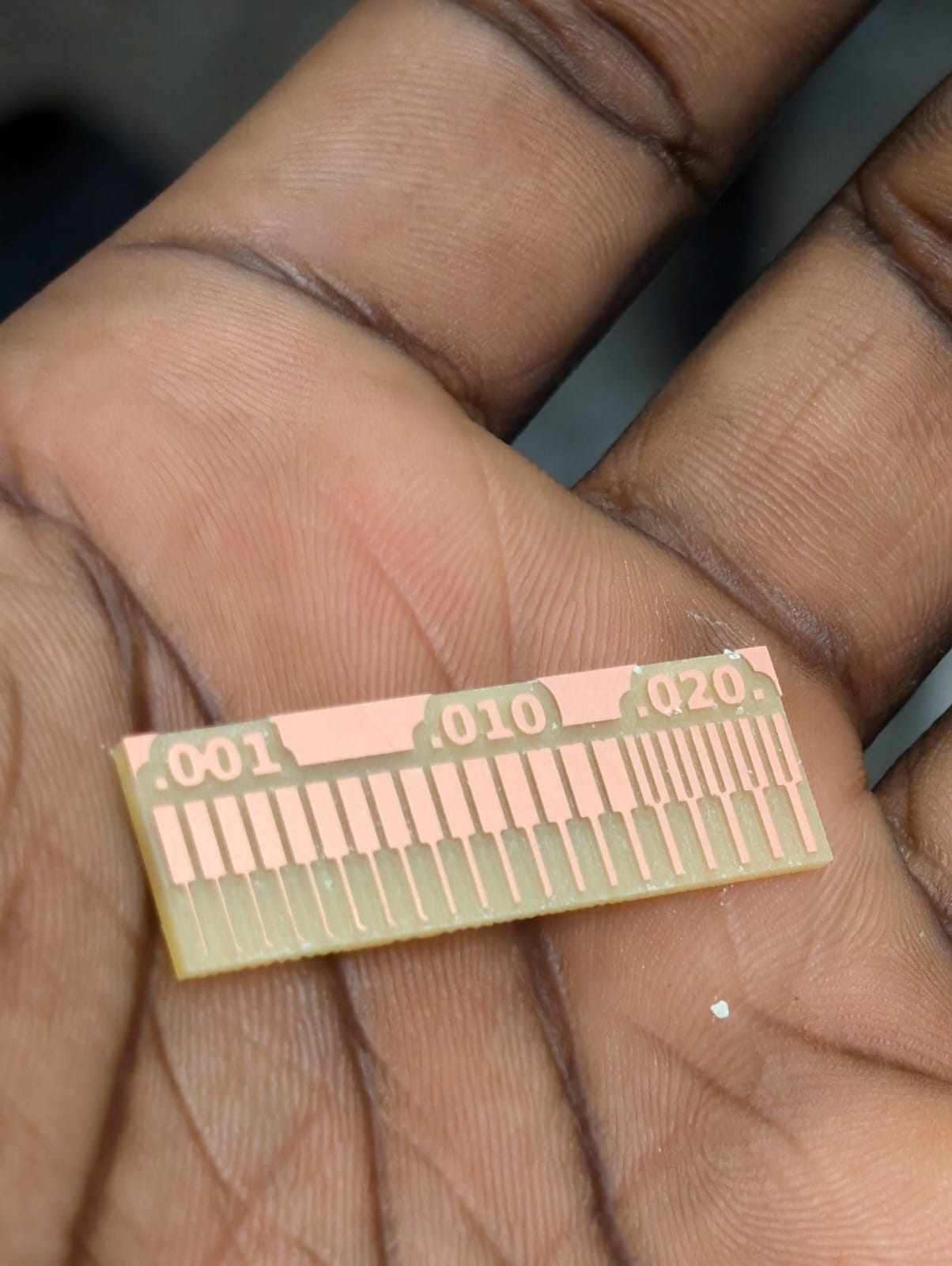
Moving on to the design rules for our in-house PCB production, Diana stressed the importance of maintaining trace widths of at least 0.3 mm to ensure robust connections, with a minimum clearance of 0.2 mm between traces to prevent accidental shorts. For vias, she recommended a drill size of 0.6 mm to facilitate easy soldering access. Diana also explained the significance of wide ground planes to reduce electrical noise and improve stability, which is especially critical for components like the ESP32.

I decided to try measuring temperature using an NTC thermistor because it’s super sensitive to temperature changes. To make the readings more accurate, I used a 4-wire bridge configuration in my PCB design, which helps reduce errors from the resistance in the wires. This setup allowed me to separate the voltage supply from the sensing lines, so any resistance in the wiring wouldn’t interfere with the thermistor’s readings. The 4-wire setup is great for precise measurements, as it minimizes voltage drops that could throw off the accuracy. Designing the PCB with this configuration required careful planning of where each connection would go to make sure the thermistor could work at its best.

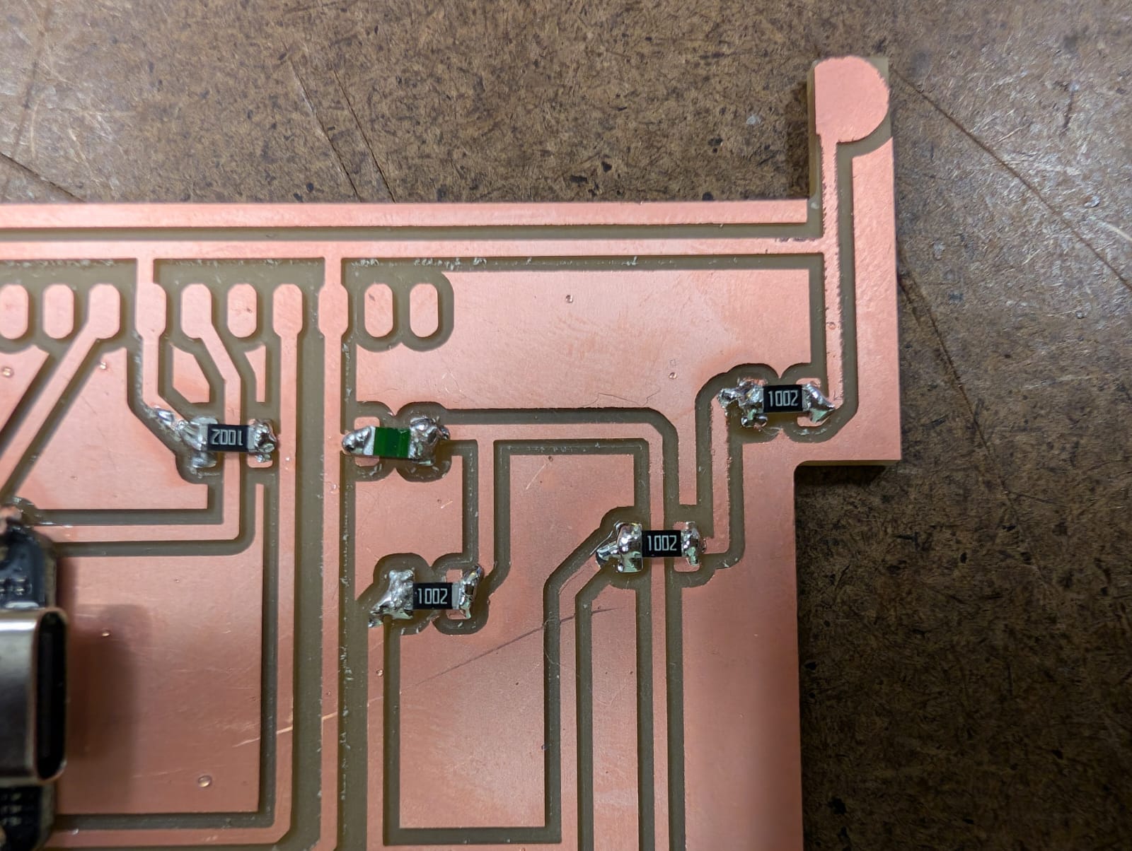
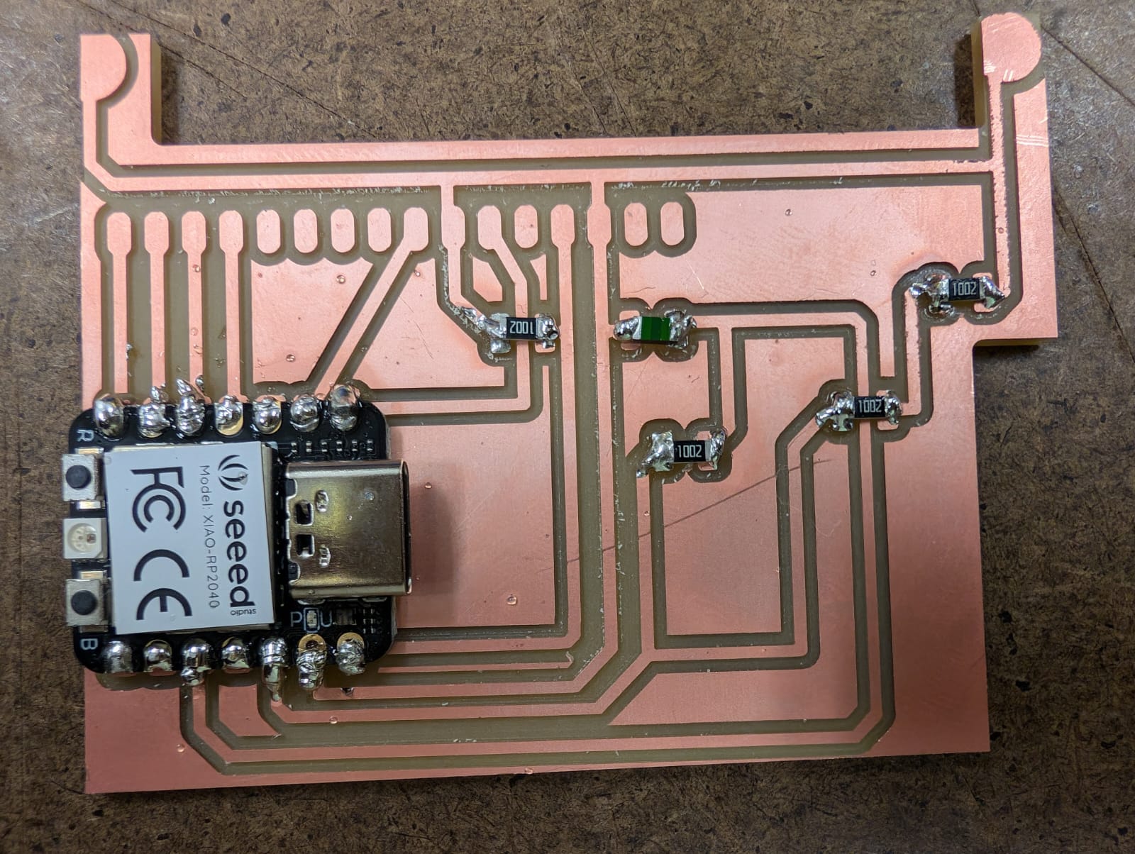
For the board itself, I went with the XIAO Seed RP2040 microcontroller—it’s small, reliable, and perfect for this type of temperature-sensing project. I paired it with an NHQ103B375T10 thermistor, which has a 10KOhm resistance at 25°C and a B-value of 3750K, making it great for precise temperature readings. I built a simple circuit with the thermistor and three 10K resistors, forming a stable bridge that could accurately respond to temperature changes. This setup allowed the thermistor to provide data that the RP2040 could easily read, and I made sure to arrange the components on the PCB in a compact layout, keeping everything neat so the microcontroller could pick up on the thermistor’s readings effectively.

After putting the board together, I wrote the code in PlatformIO, which is an excellent IDE for embedded programming. My code was set up to read the analog input from the thermistor and convert it into a temperature reading using the thermistor’s resistance curve. However, I hit a roadblock when I tried uploading the code to the board—my Mac wasn’t detecting the RP2040 chip, and it didn’t even show up in the list of connected USB devices. I double-checked the USB connection, tried different cables, restarted PlatformIO, and looked into my Mac’s USB settings, but nothing seemed to work. Without being able to upload the code, I couldn’t test the circuit in real time, which was frustrating since I was eager to see the results.

To troubleshoot, I went over every connection on the board with a multimeter to make sure everything was wired correctly. I checked the voltage and current across the thermistor and resistors, and everything seemed to be receiving the expected levels. This confirmed that the circuit itself was sound, with no loose connections or short circuits, and the multimeter readings were exactly as they should be. Even though the hardware seemed fine, my Mac still wouldn’t recognize the RP2040, suggesting that the issue might be with the USB connection or maybe even the board’s firmware rather than the physical setup.
