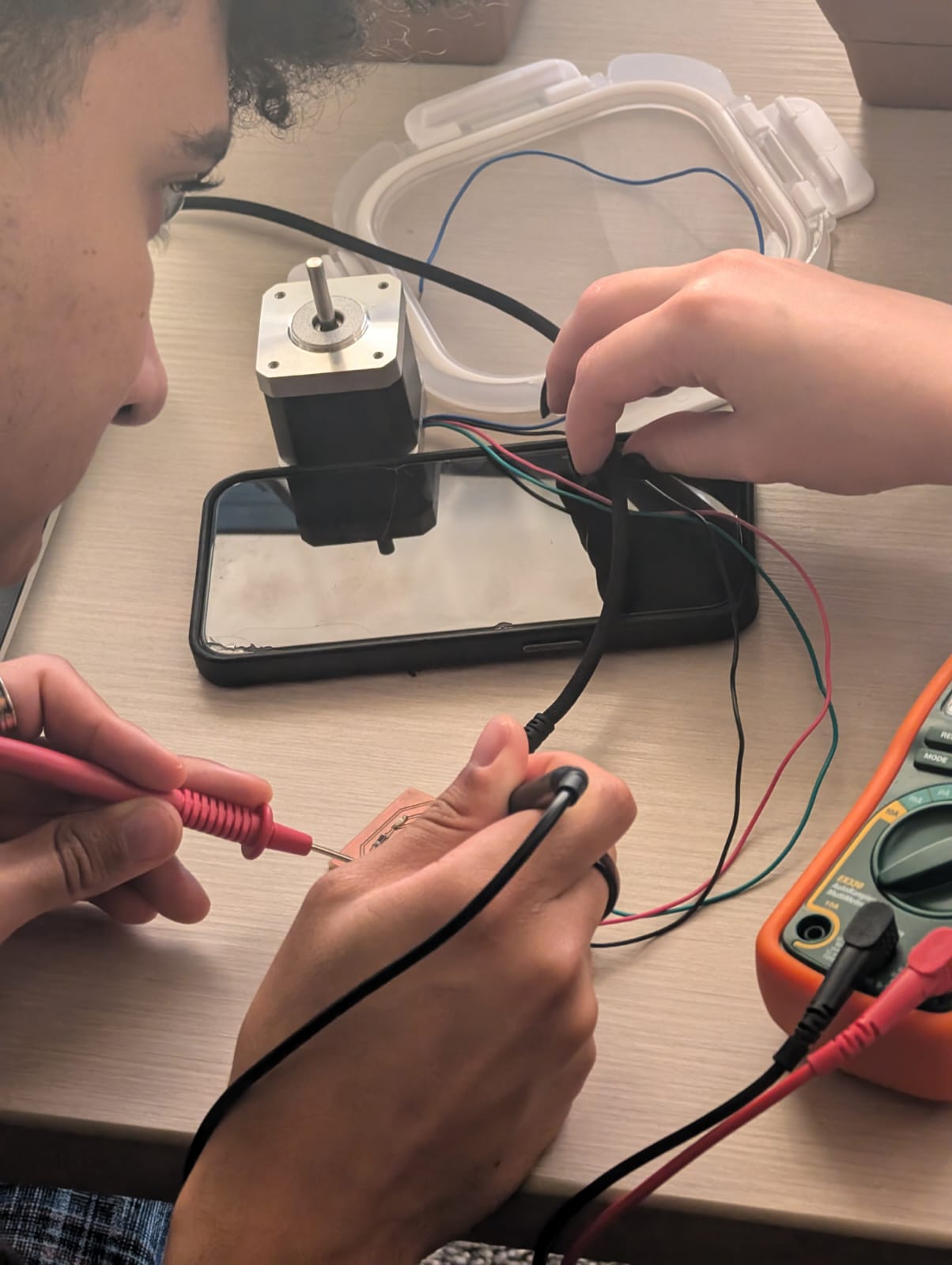
Diana, our TA, walked us through how to probe an input device to check its analog levels and digital signals. She started by breaking down the basics of analog and digital signals, explaining how they work in circuits and why they’re essential. She emphasized the importance of accurate measurements, showing us how to pick up on the subtle variations in analog signals versus the straightforward on-off nature of digital signals. Using a multimeter and oscilloscope, she demonstrated how to monitor voltage changes for analog readings, which can vary depending on the sensor output, and how to identify binary states for digital signals. The session was a fantastic introduction to understanding how input devices communicate with microcontrollers and how to interpret these signals, which is crucial for troubleshooting and circuit analysis.

I began with designing a printed circuit board (PCB) layout in KiCad to integrate the Xiao Sense S3 microcontroller and the Adafruit MEMS I2S microphone. I started by using the schematic editor to create the logical connections between the components. I mapped the Xiao Sense S3 pinouts, focusing on the I2S communication lines: BCLK (Bit Clock), LRCLK (Word Select/Frame Clock), and DATA, as well as power (3.3V) and ground (GND). I placed the symbols for both the Xiao Sense S3 and the I2S microphone in the schematic and connected the necessary pins using wires. After finishing the schematic, I ran an electrical rules check (ERC) to ensure there were no short circuits or open connections. Once everything was validated, I moved to the PCB layout, where I imported the components into the PCB editor. I positioned the footprints for the Xiao Sense S3 and microphone to minimize trace lengths and optimize space. I routed the I2S traces carefully to maintain signal integrity, ensuring the clock and data lines ran parallel and were well-spaced to reduce noise. I also added a ground plane to provide clean grounding, which is essential for accurate audio signals. After running the design rules check (DRC) to confirm there were no errors, I exported the design as Gerber files for milling.
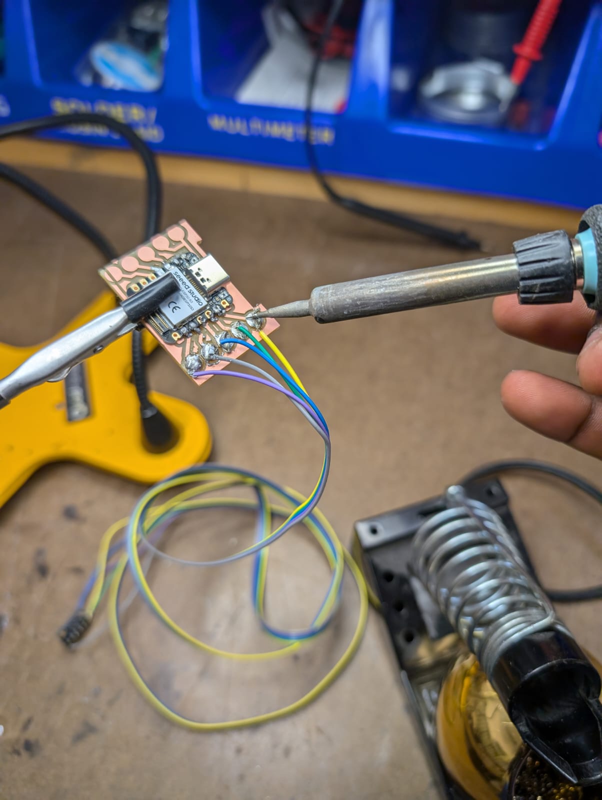
With the Gerber files ready, I moved on to milling the PCB using the Rolland SRM20 machine. I started by securing a copper-clad board onto the milling bed and loaded the PNG files into the machine. The mill etched out the traces, creating isolation paths while keeping the connections precise for the Xiao Sense S3 and the MEMS I2S microphone. After the traces were milled, I drilled any necessary vias and cleaned the board to remove leftover debris and copper dust. Once I was satisfied with the milling, I began soldering the components. The Xiao Sense S3 was small, so I carefully applied flux to the pads and soldered the microcontroller in place, making sure all connections were solid. Then, I soldered the Adafruit I2S microphone breakout, ensuring the pins for BCLK, LRCLK, DATA, 3.3V, and GND were correctly connected. I used a multimeter to check for continuity and confirm there were no solder bridges or cold joints. After cleaning the board with isopropyl alcohol to remove flux residue, I inspected it one final time to ensure it was ready for testing.

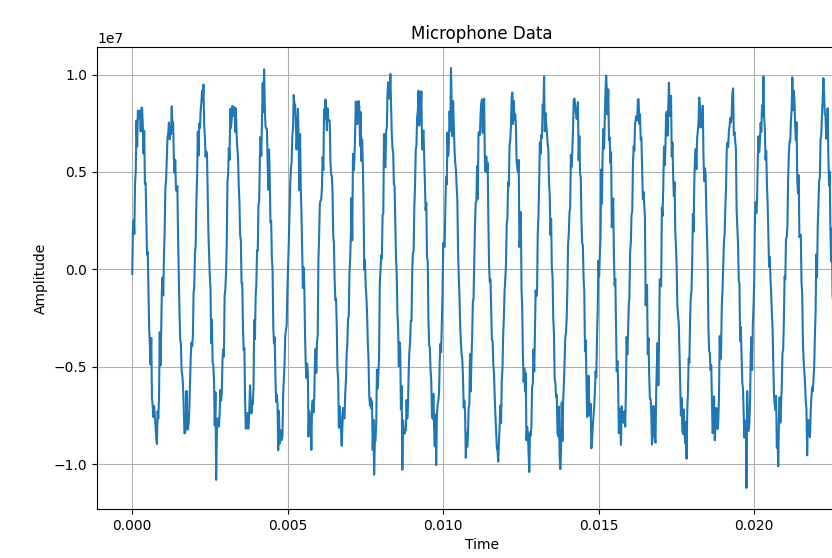
Once the hardware was complete, I wrote the Arduino code to sample audio data from the MEMS I2S microphone and display it in real time. I opened the Arduino IDE and wrote a script to initialize the I2S interface, set up the required pins, and configure the sampling rate to 44.1 kHz. In the loop function, I used I2S.read() to continuously collect audio samples and store them in a buffer. I sent this data over a serial connection to my computer, where I planned to display the real-time waveform. On the computer, I wrote a Python script using matplotlib and pyserial to read the incoming data from the serial port and plot it dynamically. The script updated the graph with new chunks of data, creating a smooth, real-time visualization of the audio waveform. Initially, there were some issues with misaligned data and buffer overflows, but after debugging and fine-tuning the code, the system worked seamlessly. It was a satisfying moment when I saw the waveform updating in real time, successfully combining the hardware design, soldering, and coding into a functional project.

