Output Devices Documentation
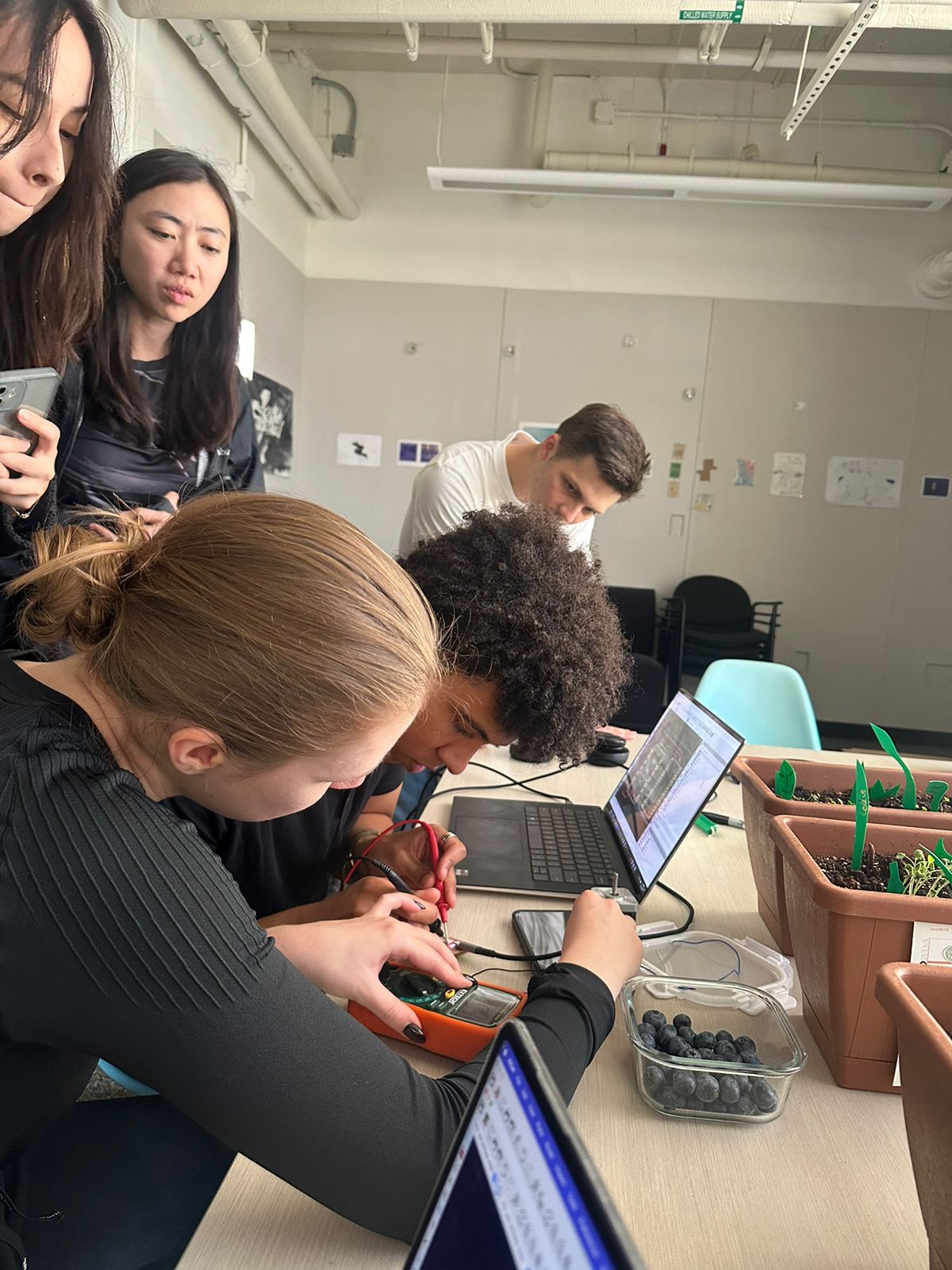
Diana, our TA, began the group session by teaching us how to measure the power consumption of an output device using a multimeter and oscilloscope. She reminded us of fundamental electronic principles and circuit concepts, emphasizing the importance of understanding current, voltage, and resistance relationships. Diana demonstrated step-by-step how to connect the multimeter and oscilloscope correctly to measure both current draw and voltage across the device. She also highlighted safety tips and the importance of taking multiple readings for accuracy. Her clear explanation of power calculation laid a strong foundation for analyzing and optimizing our circuits.
KiCAD Design and DRC Checks
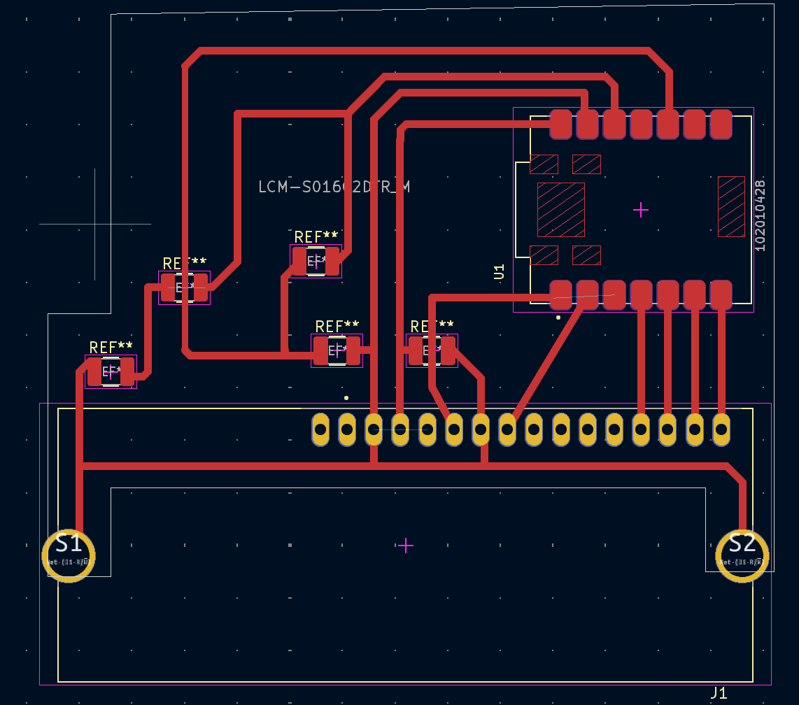
Creating this PCB was a detailed process, beginning with the design stage in KiCAD. I first laid out the schematic, placing components like the XIAO RP2040 microcontroller and the LCM-S01602DTR/M LCD in a 4-pin parallel connection. After the schematic was complete, I moved to the PCB layout, carefully routing the traces to ensure a clean design with minimal interference. I ran DRC (Design Rule Check) in KiCAD to catch any potential issues, verifying that all connections were intact and adhered to the design rules. To simulate the circuit’s functionality, I used Falstad to get a preliminary sense of how everything would work before moving to physical manufacturing.
Milling with Roland SRM-20
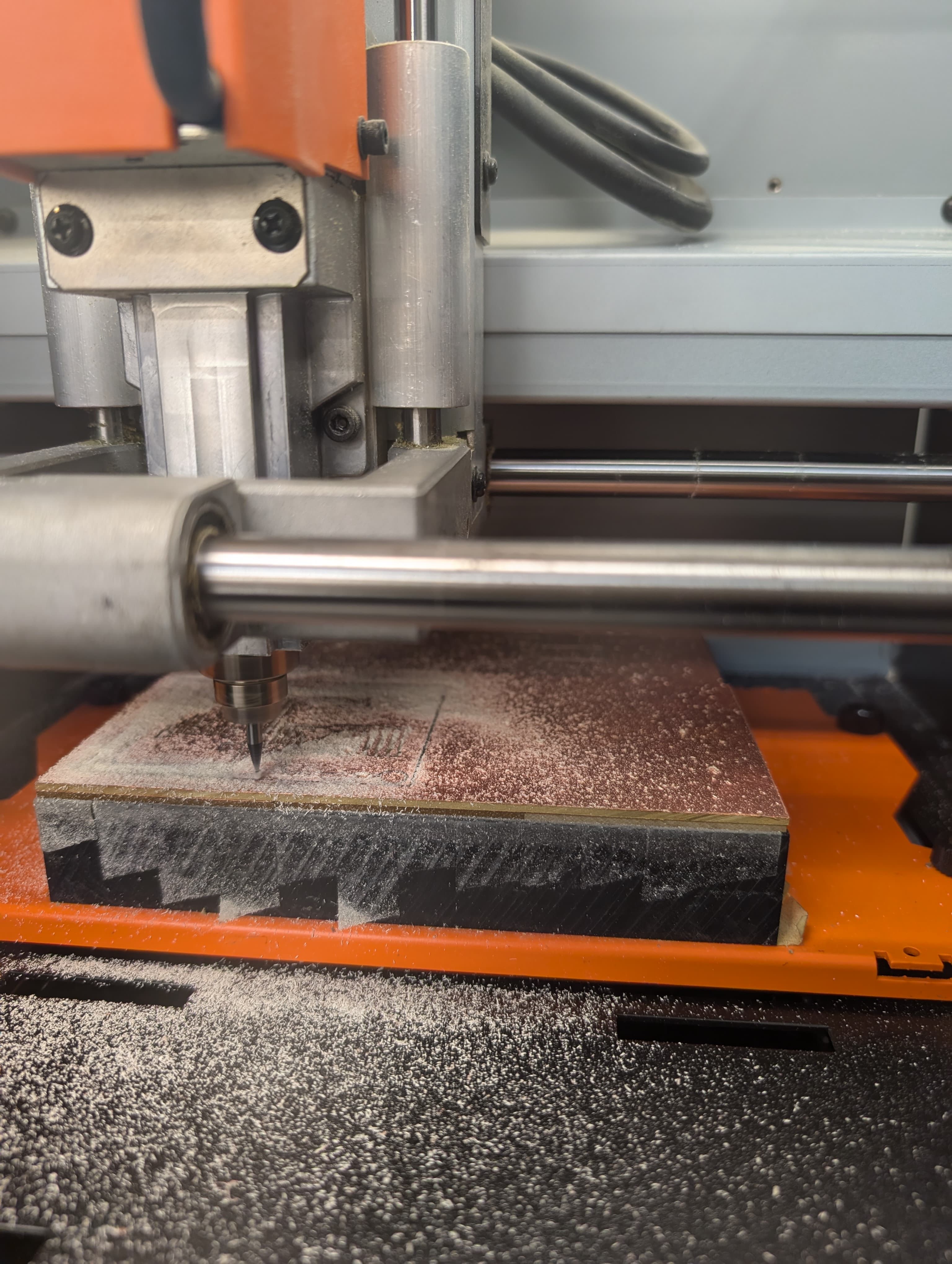
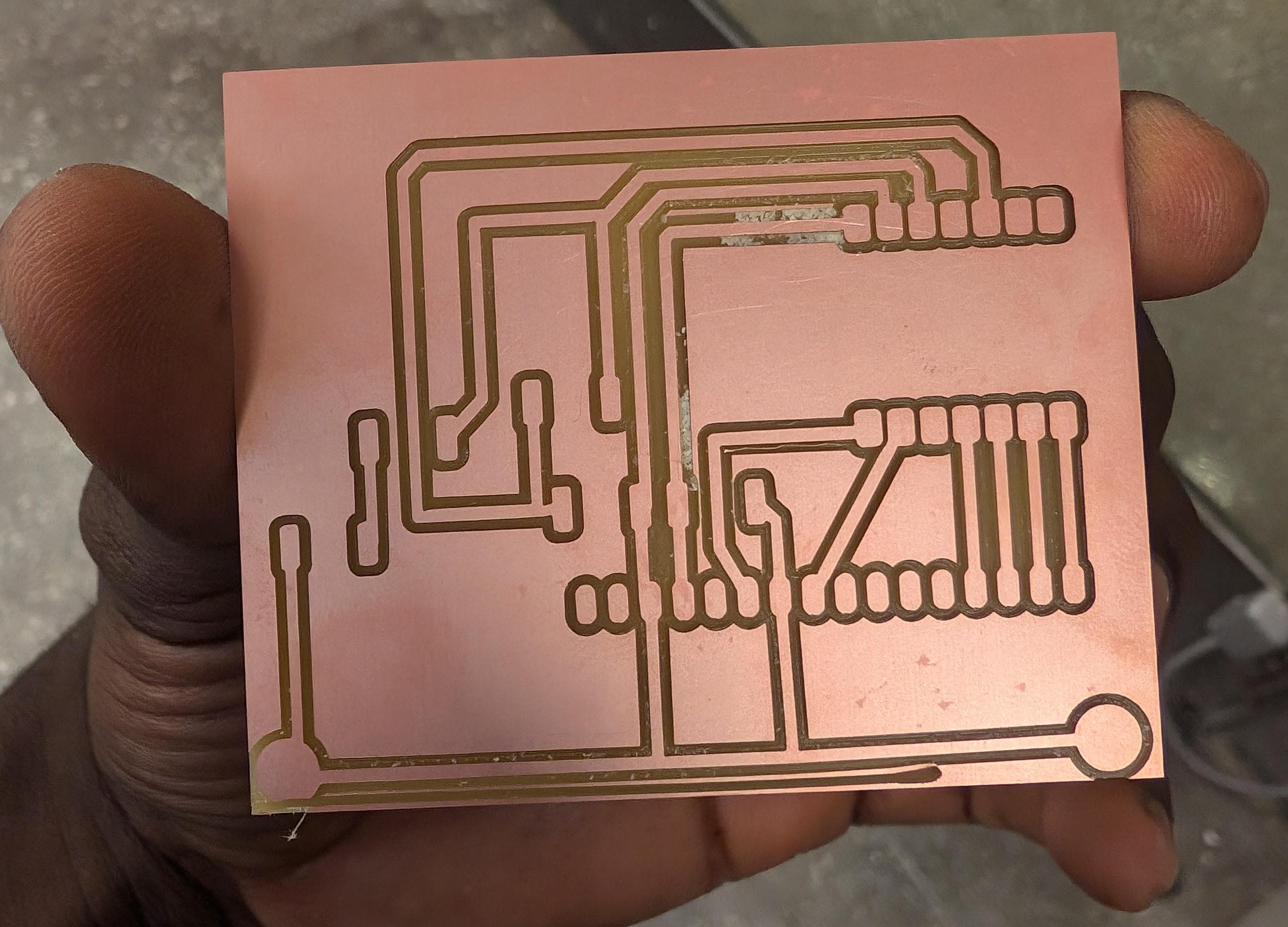
Once the design was verified, I milled the PCB using the Roland SRM-20 milling machine. I prepared the copper board and loaded my design file, carefully setting the depth and speed to ensure precise milling. The SRM-20 carved out the traces accurately, leaving a clean board ready for components. After the milling, I inspected the traces to confirm there were no unwanted connections or breaks in the circuit.
Soldering Components
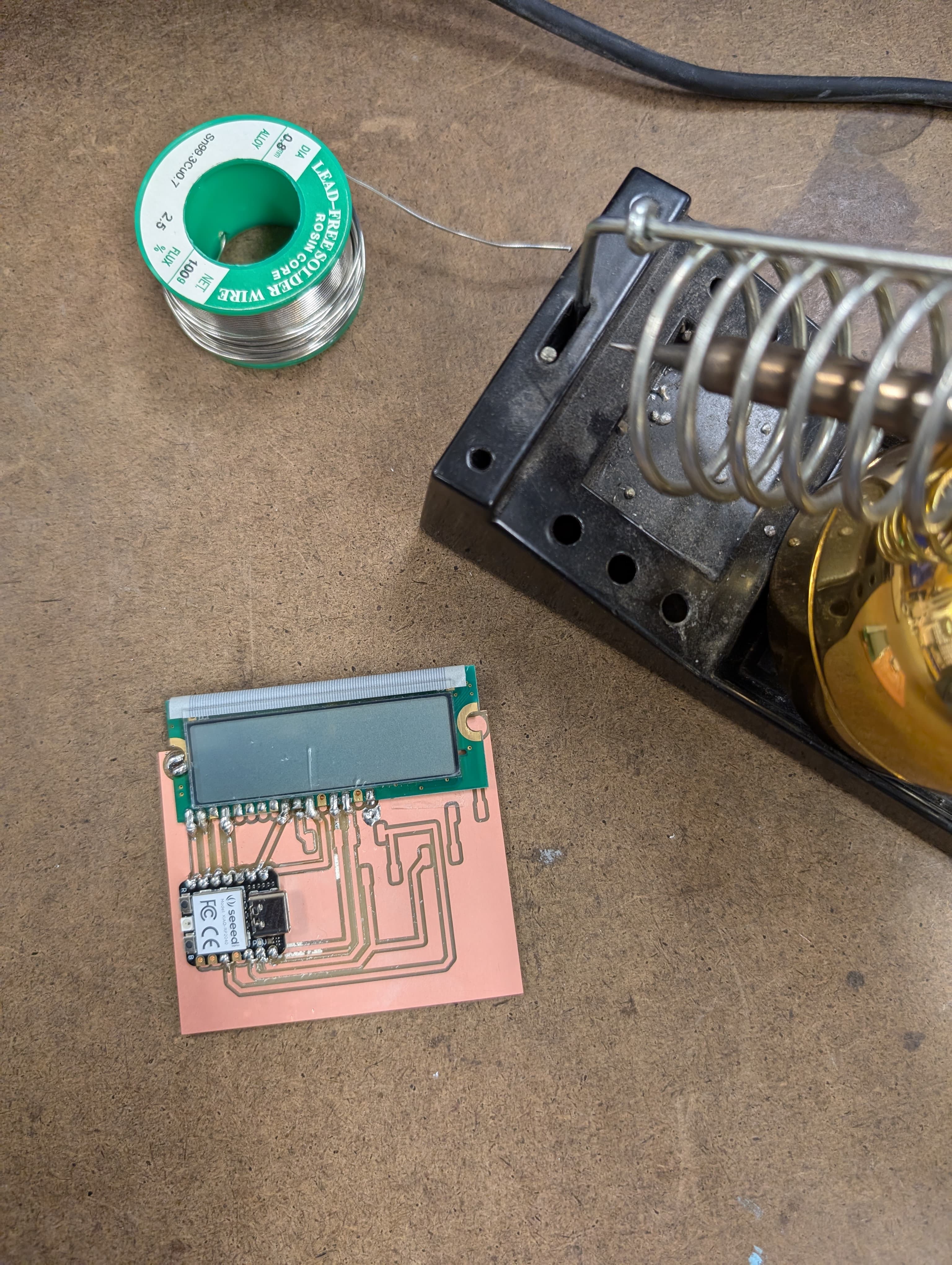
Next, I soldered the components onto the board. The XIAO RP2040 was the primary chipset, and I made sure each pin was connected precisely to its designated trace. The LCM-S01602DTR/M LCD module was soldered in parallel configuration with four data lines, which would allow it to display information based on commands from the RP2040. Careful soldering was crucial here to avoid any bridges or loose connections, as the LCD needed a stable connection for the display to work correctly.
Uploading Code with PlatformIO
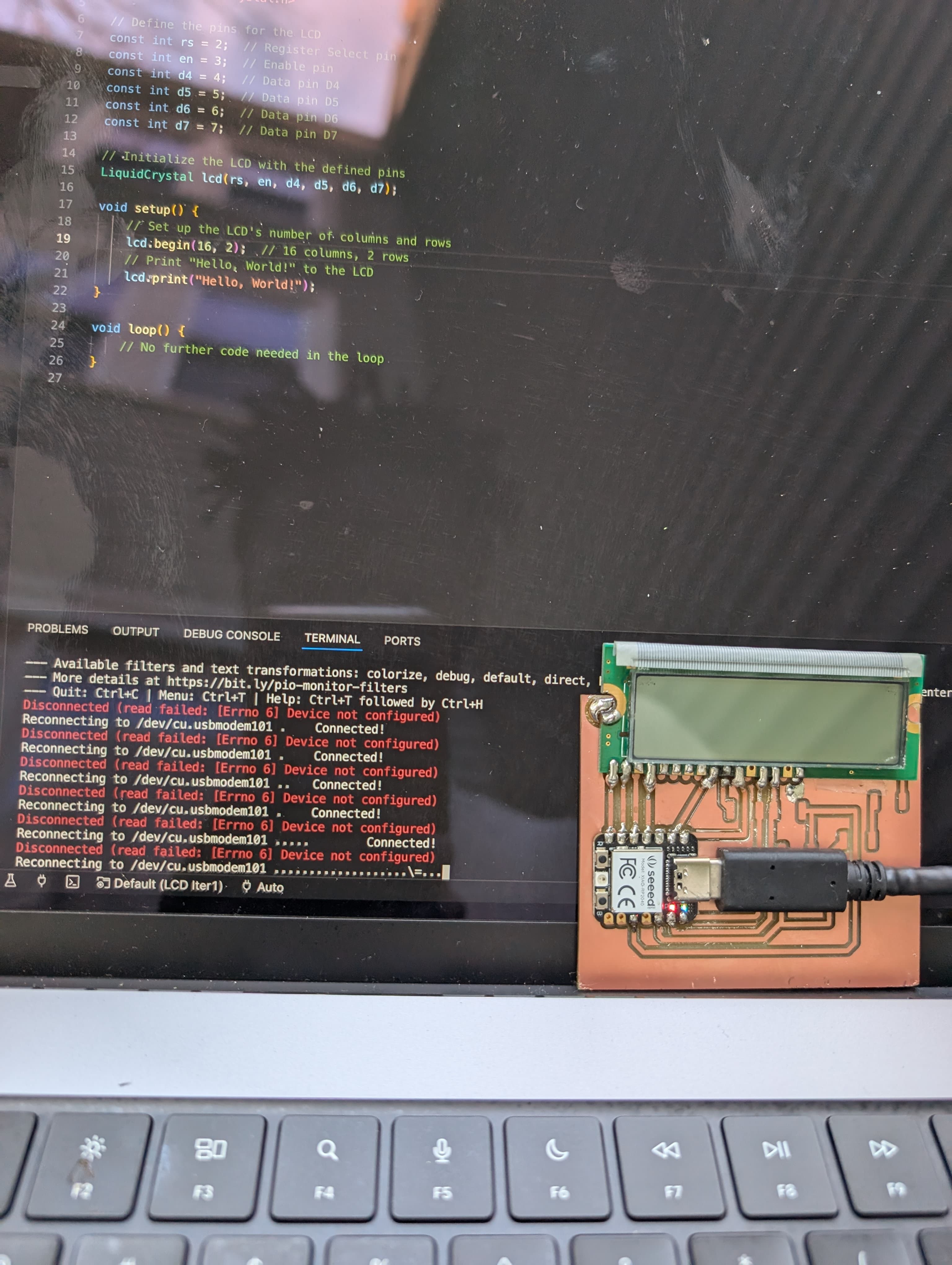
With the PCB assembled, I moved on to programming the RP2040 using PlatformIO. Writing code in PlatformIO, I set up the LCD with the required libraries, defining the correct pins and initializing the display. After setting the LCD to 16 columns and 2 rows, I coded a basic "Hello, World!" display to verify that the board was functional. PlatformIO allowed me to upload the code directly to the RP2040, making it easy to iterate and test.
Debugging the PCB
However, after powering up the PCB, I noticed that the LCD did not display the expected output. I checked the power distribution across all components with a multimeter and confirmed that each part was receiving the correct voltage. After ruling out power issues, I turned my attention back to the code, double-checking pin assignments and the LCD initialization routine. Despite the code appearing correct, I went through additional troubleshooting steps, testing each connection to identify any potential flaws. The board is still a work in progress as I continue to refine the setup.
