Project: Sword Making
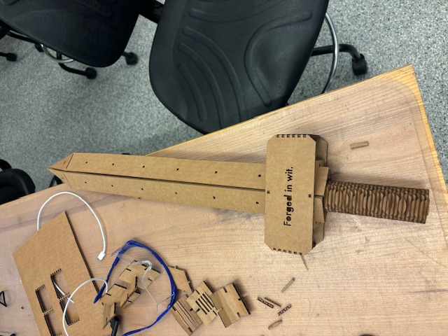
This week, I sought to make a cardboard sword with a sharp(ish) side and a flatter side, translating to a blade cross-section with angles of 60 and 120 degrees. I started by developing the blade in Fusion 360. A challenging aspect was figuring out how to get the cardboard blade faces to meet at an angle and stay there.
To address this, I decided to create cross-sectional supports in the shape of diamonds with teeth on each face (as shown in the first image). These diamonds had lengths of 40mm on the shorter axis and 80mm on the longer axis. Next, I designed four identical blade faces, each 40mm wide and 50cm long, with holes for seven diamond fittings. You can see the final design with the diamond fittings in the following photos:


I then modified the blade design to have a pointy tip. This was achieved by creating an asymmetrical triangle at the top with angles of 71.2 degrees and 83 degrees at the base. This choice allowed the blade faces to meet at a comfortable angle. Additionally, I added a small rectangular cut at the top for easier bending, as shown in the 6th photo. The completed blade can be seen in the 7th photo.


One problem I encountered was that the cardboard wasn't entirely flat, causing difficulties with keeping the blade faces attached to the diamond cross-sections. Perhaps the teeth could have been wider, but my solution was to add two supports at the bottom of the blade (the non-pointy end). These supports were rectangular with diamond shapes inside and also had teeth to fit into the handle faces inscribed with "Forged in wit." in Futura font.


For the pointy end, I added holes that allowed me to feed small cardboard filaments through, tightening and trimming them to hold the blade faces together. This enabled the blade to stay in place without using rubber bands.


With the blade secure, I moved on to the handle. I started by making two plates with "Forged in wit." cut out from the middle. These plates measured 15cm across and approximately 6.5cm tall. Teeth were added along the shorter edges to fit into the connecting pieces holding the two handle faces together. However, getting all four pieces to fit was more challenging than expected, requiring experimentation with uneven teeth and hole sizes. The longer plates used symmetrical 3.4mm wide teeth and holes, but the holding pieces had 4.2mm wide teeth and 2.8mm wide holes to ensure a snug fit.


As for the handle design itself, I wanted something visually distinct from the blade. Initially, I considered a tsuka handle pattern, but I ultimately opted for a design inspired by a KA-BAR knife handle, involving multiple layers of pressed-together circles. I cut 45 cardboard circles with a 4cm diameter and a 2cm x 3.4mm slit. 30 of these were stacked around a rectangular pole to create the handle.


The final result was a super sturdy weapon with the blade and handle held together securely.


One design inefficiency is currently that the pole fed through the handle is not the same pole as the one holding the diamond cross-sections together. This results in the handle coming loose from the blade quite easily. If there was a support piece or just one long pole throughout the whole sword, this would probably not be the case...
Vinyl Cutter Assignment
For the vinyl cutter portion of this assignment, I decided to keep it simple by printing a large Hot Wheels flame on white vinyl. I used transfer paper to apply the flame design onto a piece of cardboard.

Group Assignment
As part of the group assignment, we focused on characterizing the lasercutter settings in the EDS lab to determine the optimal power, speed, kerf, and joint clearance for cutting cardboard. Here’s a summary of our findings:
- Laser Cutter Settings: We found that using 100% power with a 23% speed setting was ideal for clean cuts. This allowed most pieces to fall out of the larger cardboard sheet without requiring manual pushing.
- Kerf Measurement: Our group determined that the kerf (the width of material removed by the laser cut) was approximately 0.01 inches. This was verified through several test cuts.
- Joint Clearance: Through a series of tests, we found that a 3.4mm clearance was optimal for snugly fitting cardboard pieces together. We tested various sizes and confirmed this was the best fit for creating sturdy joints without too much resistance.
Overall, this group assignment provided valuable insights into optimizing the laser cutting process and how minor adjustments can significantly impact the quality of cuts and fittings.
Reflection
This week, I learned about the complexities of designing angled structures with supports and the challenges of working with non-flat materials. I also gained experience in using laser cutters for both structural and decorative purposes. Overall, this project was a great introduction to making tangible, functional objects using digital fabrication tools.
Next Week: Embedded Programming →