Week 5
PCB Design
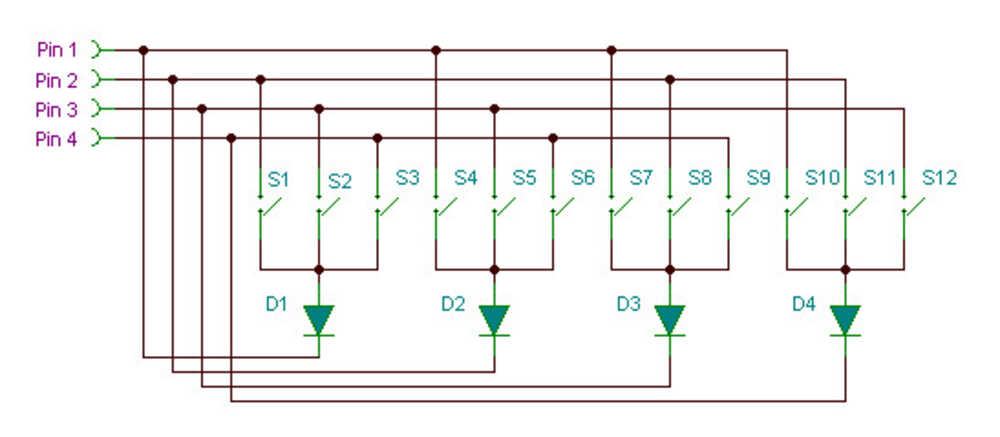
I decided I'm gonna try to make a pcb that can function as a handheld calculator. Calculators need a lot of buttons-- more than the number of input pins on a xiao-esp32-c3 -- so I looked into charlieplexing. Charlieplexing is a way of arranging inputs or outputs(in my case buttons) so you with N pins you can control N(N-1) buttons. Basically you arrange everything such that each button goes from one pin to another with direction enforced by diodes. To check which button is pressed, we loop through trying each pin as an output one by one and seeing where we get an input signal. Then we know, the button from that output to that input is pressed.


(left) charlieplexing with 3 pins,(right) charlieplexingwith 4 pins
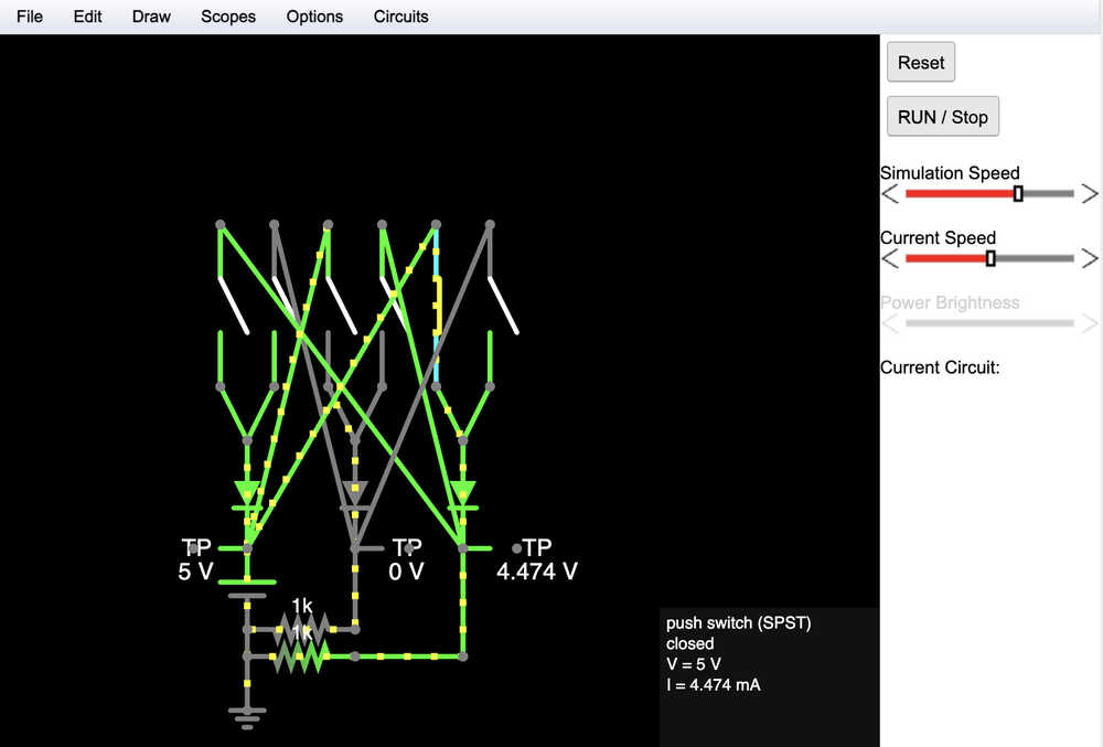
I played around a bit in falstad to see how charliplexing worked. my falstad simulation looks a little confusing but basically I just hardcoded one pin as a high input and left the other two as output.

The xiao esp32-c3 has 11 GPIO pins. I decided using 5 pins which would allow for 20 buttons seemed like enough. This also leaves 6 pins for output devices or other stuff. So I started making a schematic. I used Autodesk Eagle for PCB design because I have already been using Fusion360 in this course, so it meant one less thing to download. Some example charlieplexing schematics showed a diode along with every button and some showed less, I decided to go for less, but I'll check with course staff to make sure there's not a glaring issue with that before producing this board. Also worth noting that the esp32-c3 has internal input pull up resistors so external resistors are not needed to limit current.

In terms of arranging my pcb, I probably could've looked into diagonal charliplexing arrangements a little more, but I kinda just went for it and I managed to make something with no need for jumps so that's good. my rows and columns are roughly arranged by input and output pins. I also added a four pin header to attach an OLED display to be the screen of the calculator
