Week 6
PCB Production
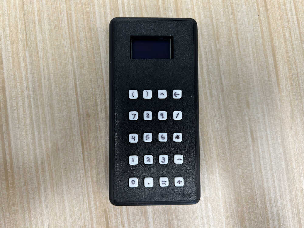
I promise there is a pcb inside, scroll down to see the innerworkings
This week was my favorite so far! I tweaked my board a little here and there. I increased the design rule distance between pads and traces so I had to do a bit of tweaking but overall it stayed pretty much the same. I was really scared that I had misunderstood charliplexing and that I was gonna go through all the work to make it and it wouldn't work, so I made a wokwi simulation to try writing some code and make sure I understood what needed to be inputs and outputs. This was moderately successful, and I came up with functioning code. I did run into an issue where Wokwi doesn't have a schottky diode so I tried using an led instead. Unfortunately the led dropped the voltage enough that a pulled down input would read low if an led was between it and ground. I verified that this wouldn't be a problem by looking at the datasheet and confirming 3.3V - 0.3V (shottky diode forward voltage) > ~2V (the HIGH threshold on an RP2040). All this is to say, I had done some double checking and it seemed like it would work.
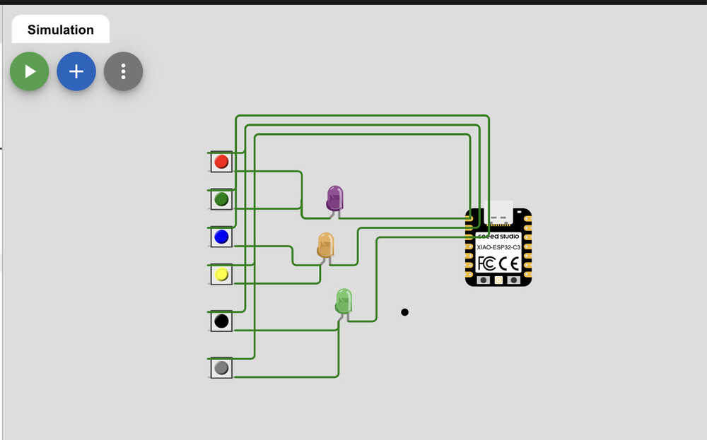
my attempt at using wokwi to simulate charlieplexing
Next, I milled my board using the openmill machine in EDS. This was a surprisingly simple process, and it came out right the first time.
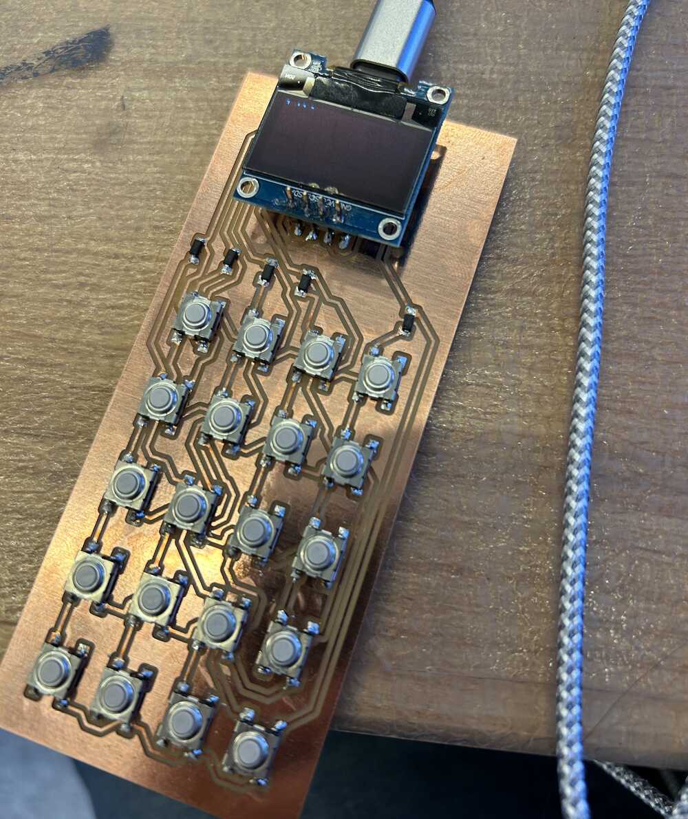
Then came soldering. I've soldered before this class so this wasn't too bad. It was really cool to solder onto a board I made myself! I soldered header pins for an OLED but wanted to get it working in the serial monitor before trying to incorporate that.
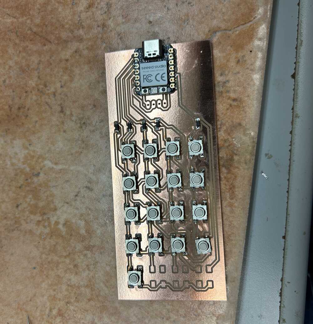
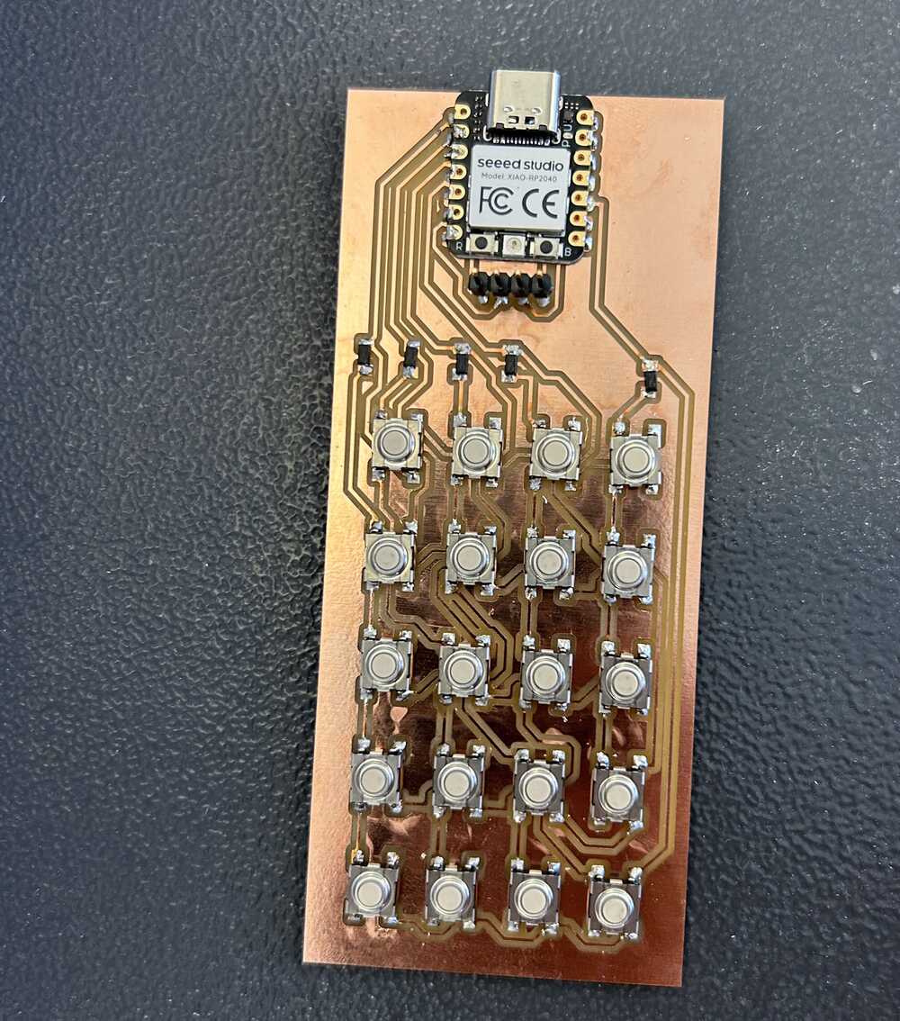
I forgot to take a picture pre-soldering so the left picture is part way through and the right is fully soldered
I started by seeing if my charlieplexing was indeed correct. I modified my wokwi code and gave it a go. This required a little tweaking and I had to add in a delay before reading input so it wasn't affected by previous outputs. But very soon it was working and you can see that code here. I miraculously got it working first try!
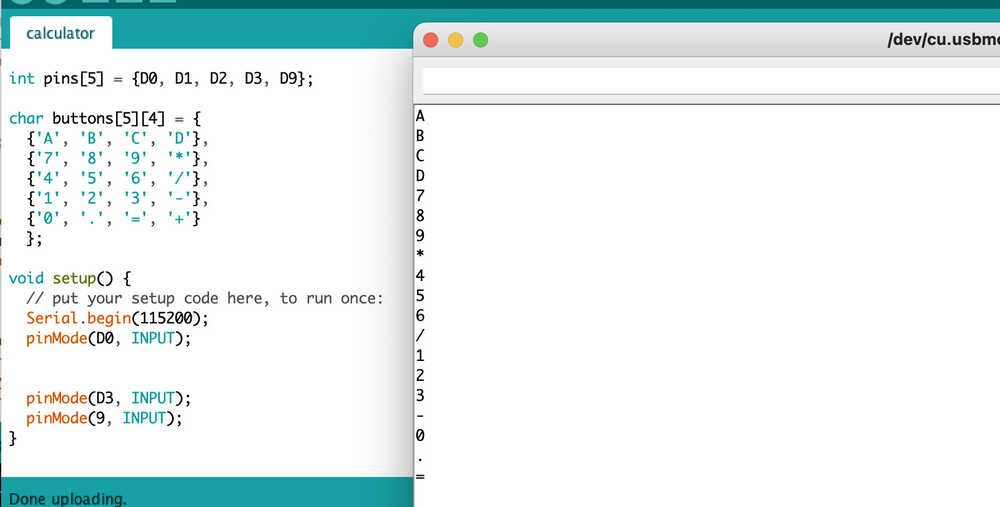
I corresponded each button to a symbol and pressed each one once to create this serial output
At this point, I was pretty sure I had already accomplished the task for the week, but I still had a lot more I wanted to do. I added onto my code to translate each button to a math symbol and then put those symbols together into a string. I used an open source library called tinyexpr to take math expression string and calculate the answer. Then I printed this answer in the serial monitor!
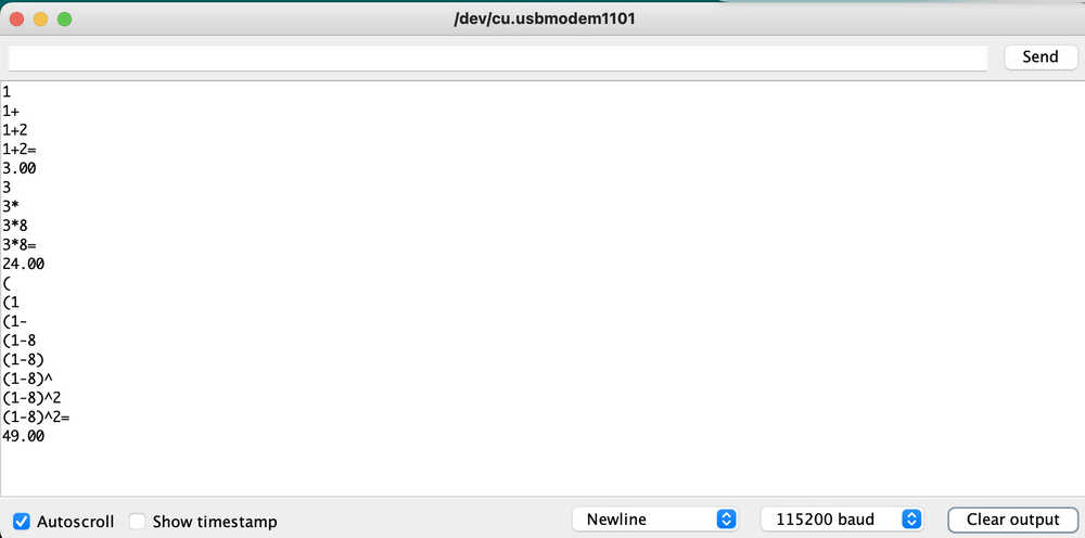
the results in the serial monitor based on button presses
Next came the OLED. I soldered it on the header pins on my board. Luckily I had ordered the pins correctly so I could just slide it in. It took me a bit to figure out how to program it. I decided to use the U8x8 library to communicate with the board. Once I figured out how to write to the screen I used my calculator code to print to the oled and I had a working calculator. Final code here
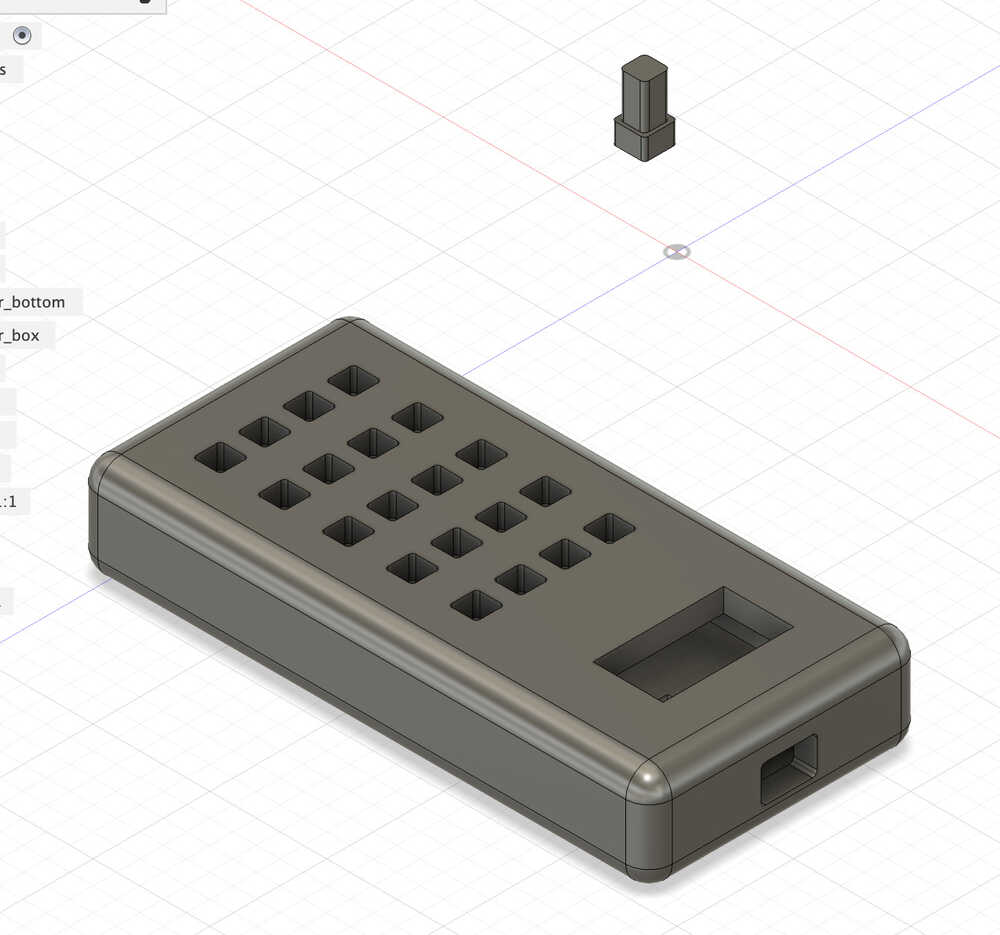
I thought it would be cool if my calculator had a case, so I CADed one and tried to 3D print it. My first attempt was close but not fully successful. For one the 3D printer ran out of material a couple minutes before finishing and was being weird about loading in new filament. I also realized a few holes were just slightly off so I made adjustments and reprinted.
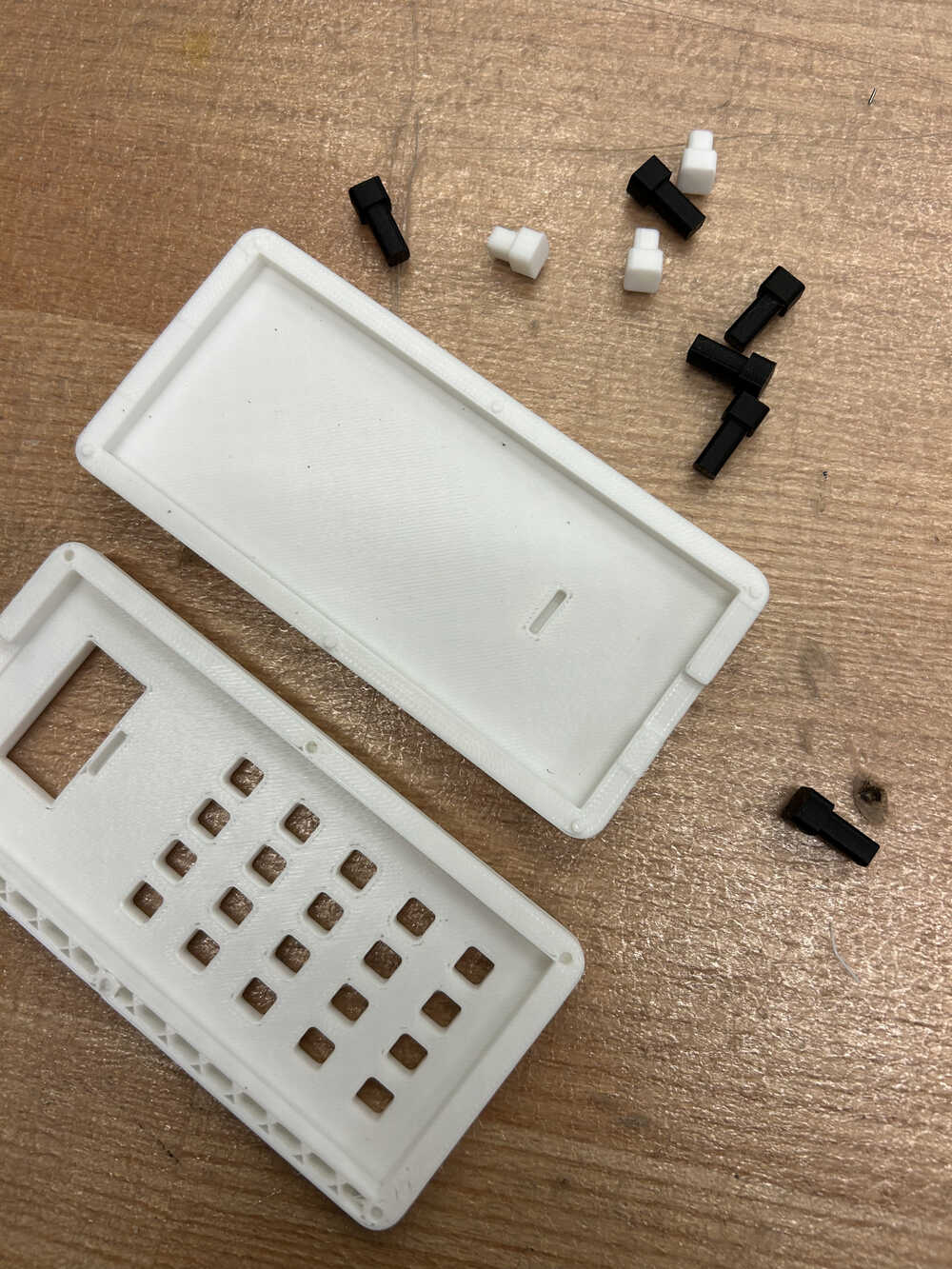
pieces that did not quite fit my pcb. you can see where the infill where the 3D printed stopped
my reprint worked! Now I have a lovely calculator!
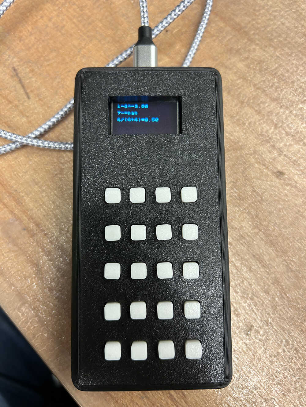
Finished calculator