Group Assignment
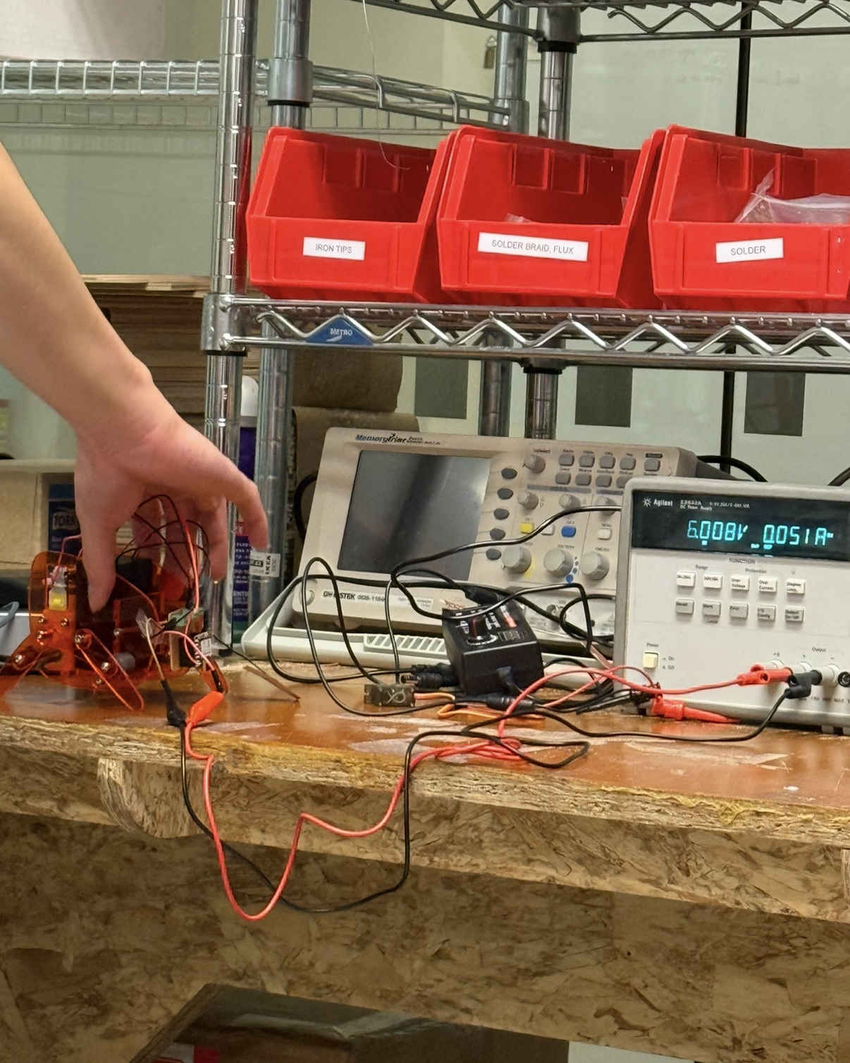
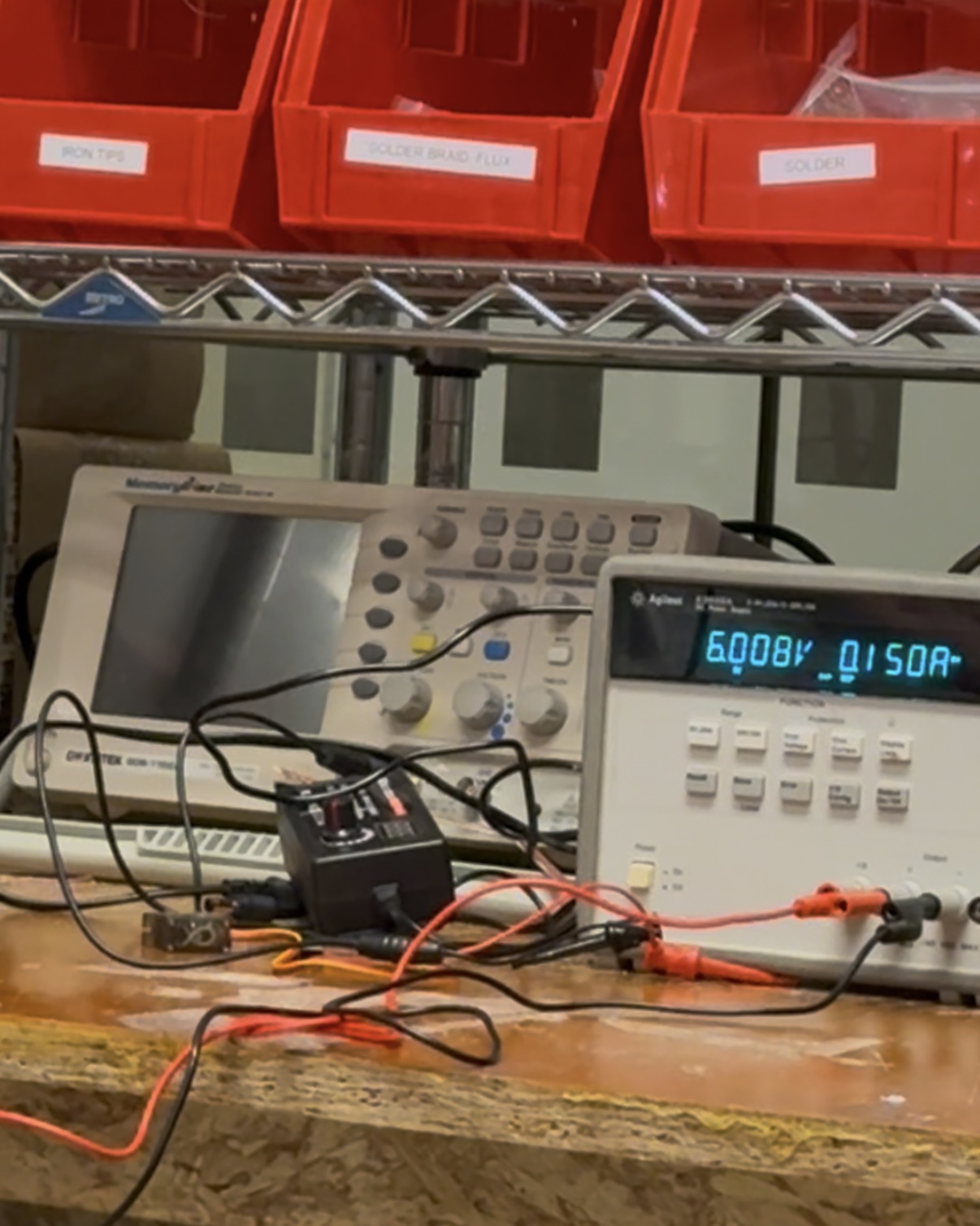
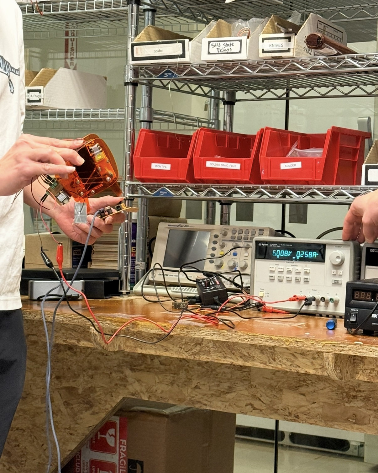
The DC power supply shows a voltage of 6V and a current of 0.258A. Using these values, we can calculate the power consumption for moving both legs of the robot as P = IV = 6 V * 0.258 A= 1.5 W. We also compared this to when only one leg was moving, which drew 0.15A, and when no legs were moving, which resulted in a current of 0.047A. This makes sense, as 0.15A - 0.047A is approximately 0.1A to move one leg, and it took about 0.258A - 0.15A = 0.108A to move the other leg. So for moving one leg, it takes about P = IV = 6 V* 0.15 A= 0.9 W, and need 0.6A more to move the other leg.
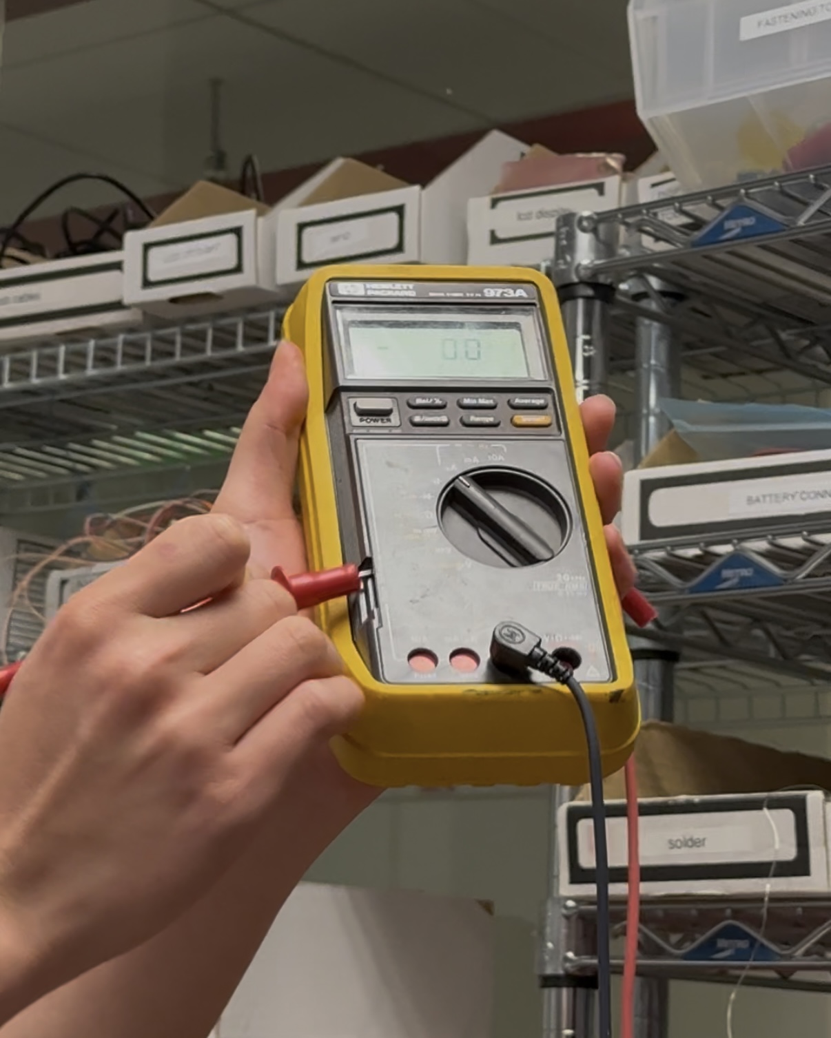
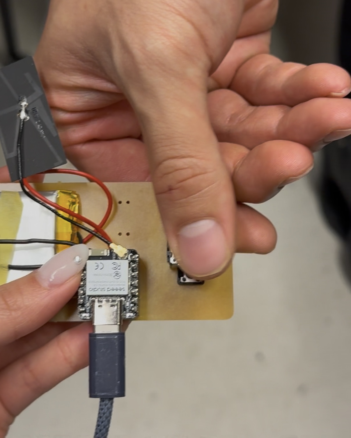
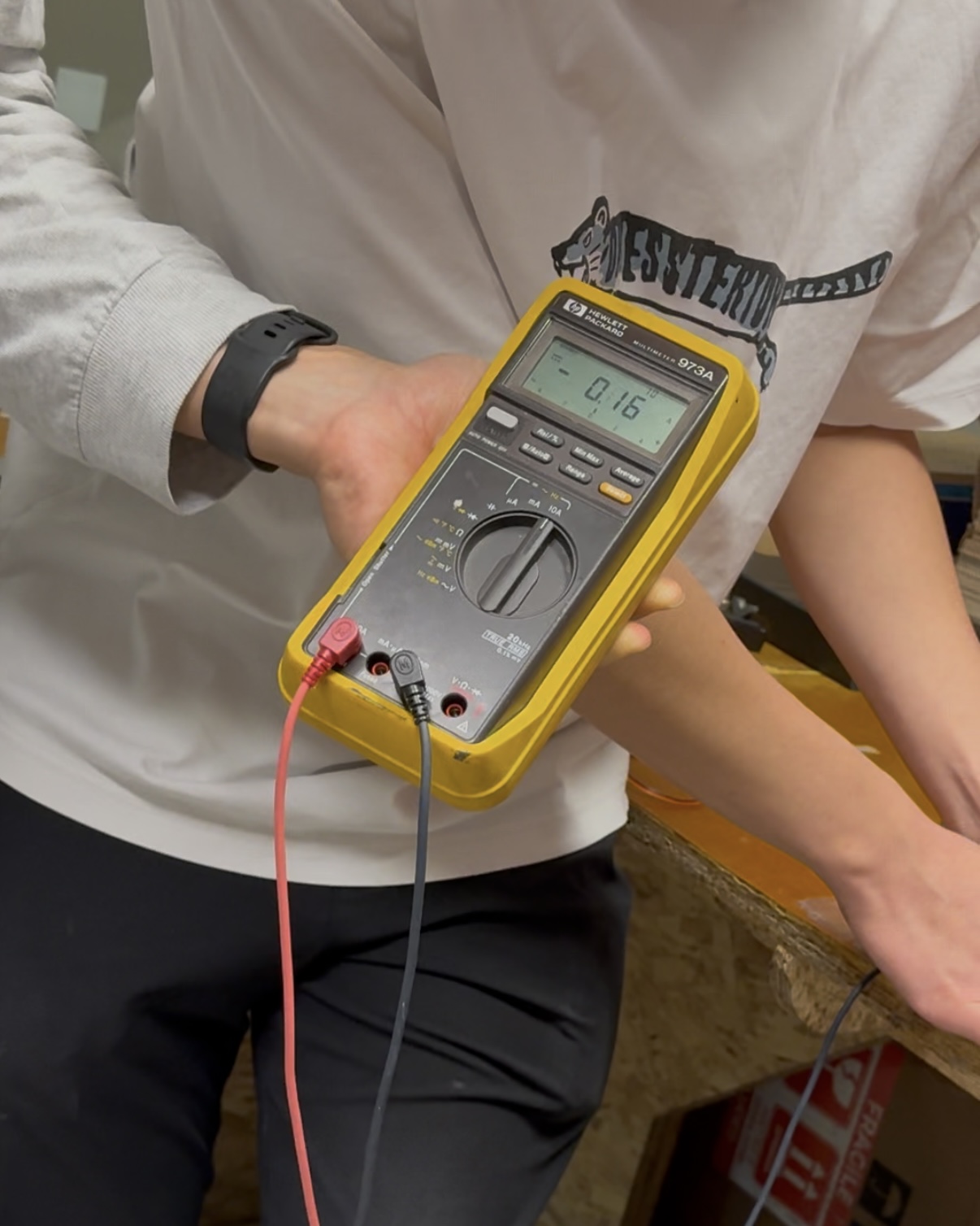
We also tried measuring current using multimeter. There was a safety pin to measure current. When moving one leg, we got 0.16A, which matches with our previous reading from the power supply!
Individual Assignment
For this week's assignment, I aimed to create an output device that will speak human voice (as a prep for my final project), but since the components were not yet shipped, I decided to do something a bit more simple: writing my name on the OLED display.
I've been working with the ESP32C3 and ESP32S3 for my past assignments, as I plan to use these microcontrollers for my final project. For this week, I wanted to try different microcontroller, so I connected my display with RP2040.
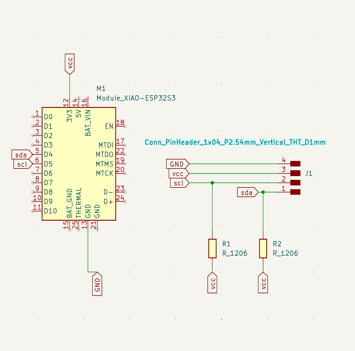
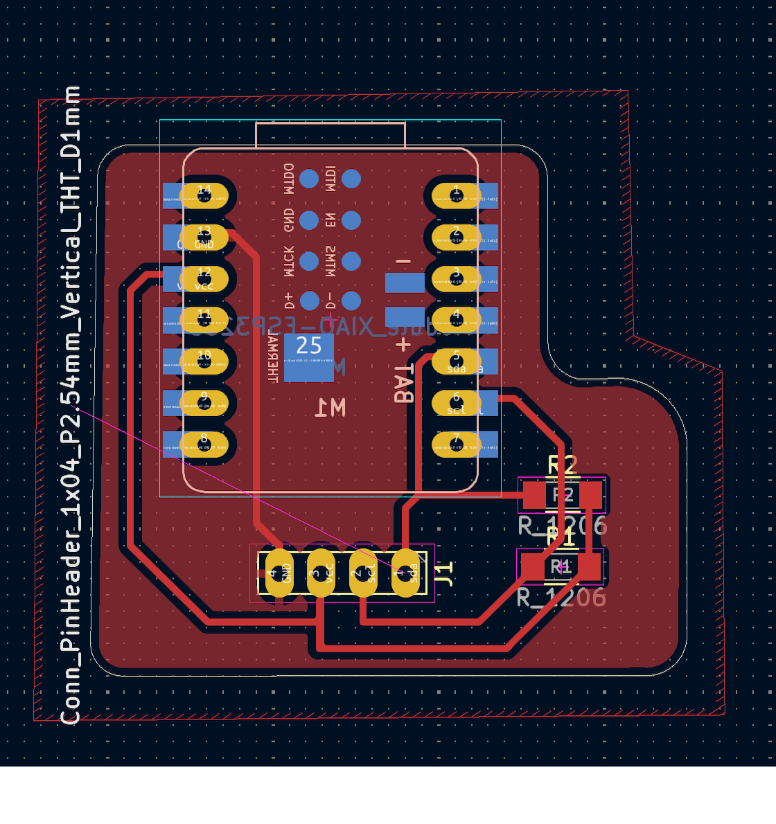
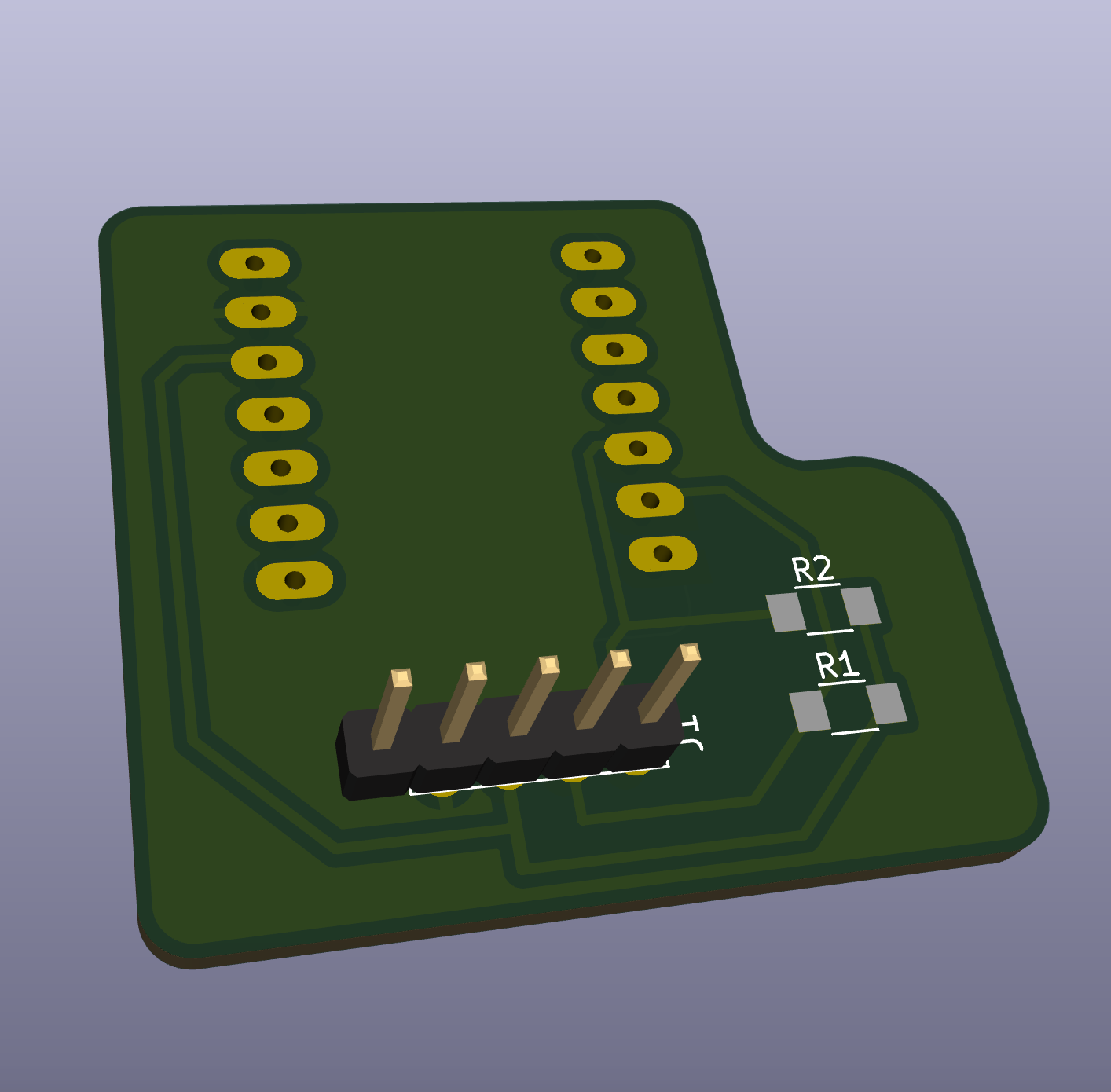
Something I newly learned this week was how to use connect header pins.
This was very useful not only for creating a more modular setup, allowing different components to be easily replaced and making the microcontroller boards reusable, but also for simplifying soldering.
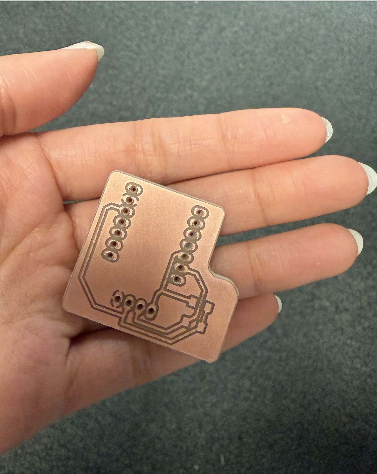
However, one important detail to remember is to flip the component in the PCB design.
This ensures that the connection logic is maintained when plugging in real components on the opposite side.
I made sure to do this for my microcontroller, but unfortunately, I forgot to flip the display connector header pin. (I should have checked this by looking at the 3D viewer!)
This oversight made soldering particularly challenging; if the display is pushed too far into the header, the solder joints do not make good contact with the display pins.


Regardless, I was able to output my name on the display.
DOWNLOAD ARDUINO CODE HERE
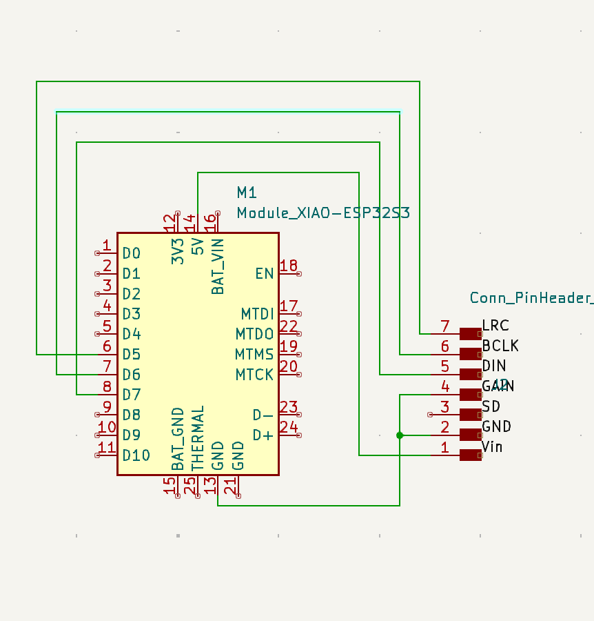
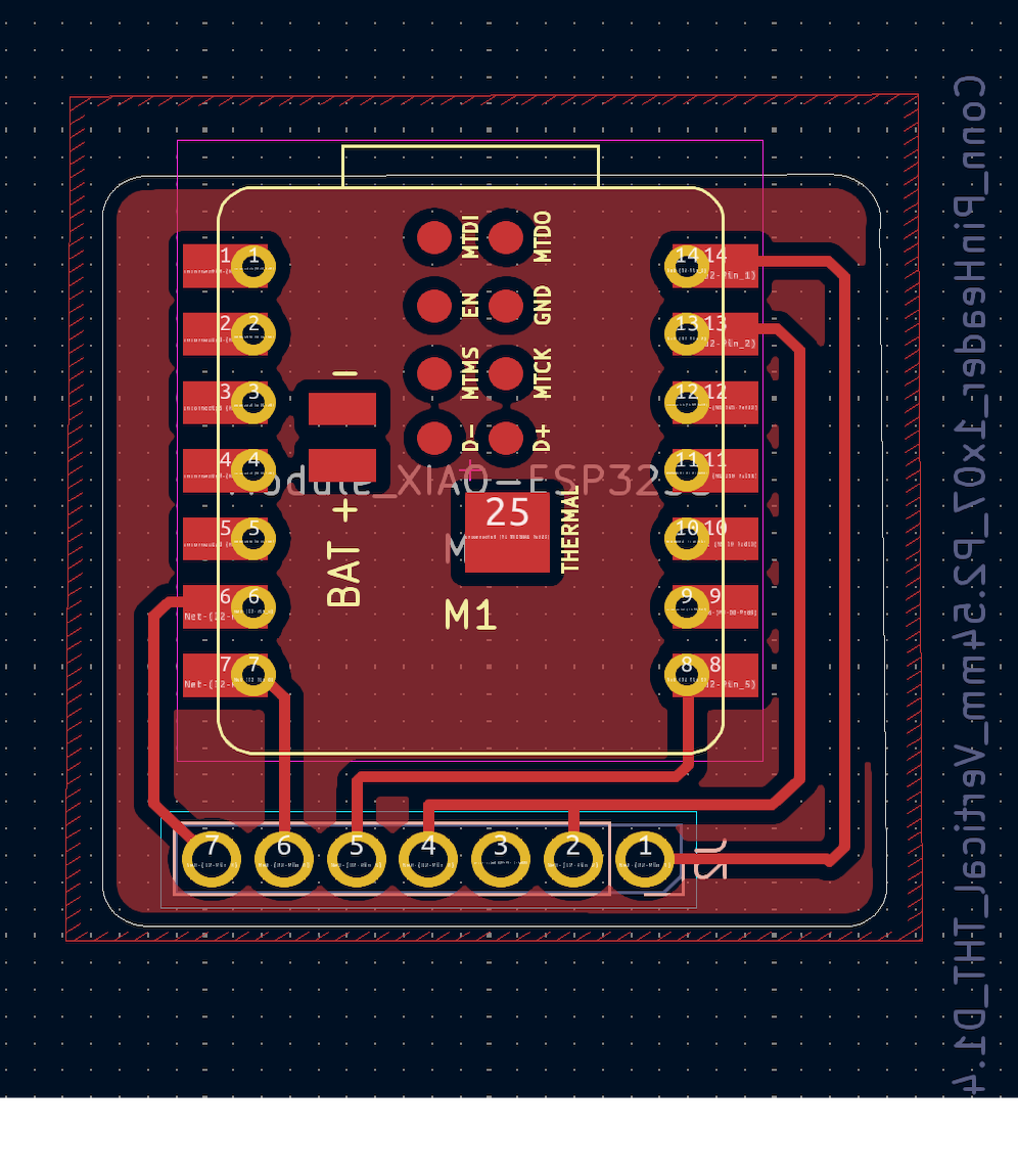
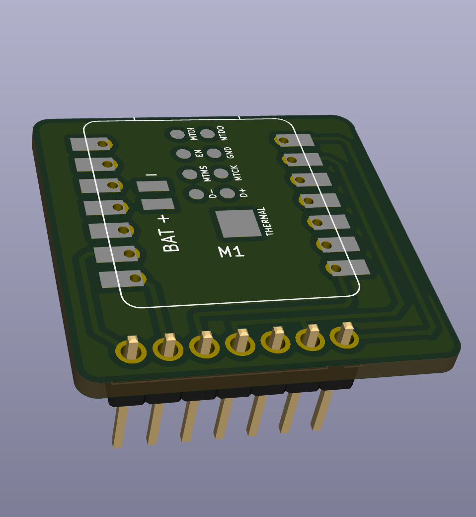
Below is the design for the human-speaking sound output that I originally intended to complete this week. Since all the components I need have arrived, I will be finishing this soon and, hopefully, connecting with the GPT API!
Also, this time, I made sure the connector header pins are facing the right direction. :)
