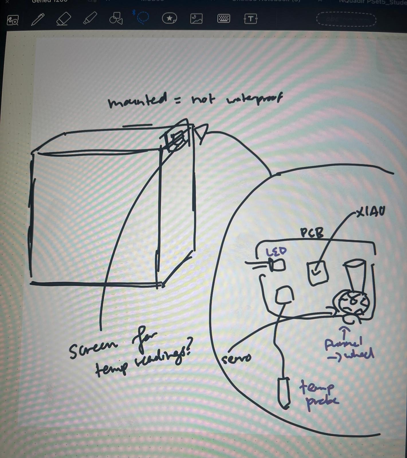
Initial design sketches and planning
I'm a fish breeder, and one of the most important parts of the hobby is measuring water parameters. For my final project, I want to measure and monitor pH, nitrites, and/or temperature. It could also be cool to make an automatic feeder because I never trust the super complex ones you can buy online.
I've updated this throughout the semester, but wanted to have a system that could "sit" on an aquarium (visible) and measure different parameters.
Initial design sketches and planning
Measured the tank dimensions to figure out how the setup would sit on the frame.

Tank Dimensions
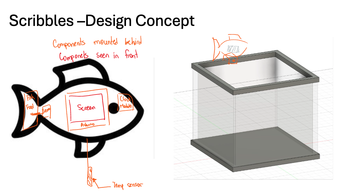
Figured out the approximate look of my design + form factor (a fish!).
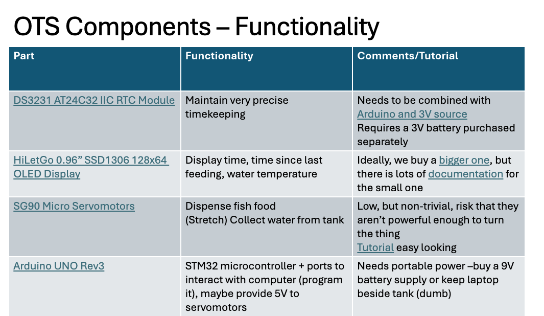
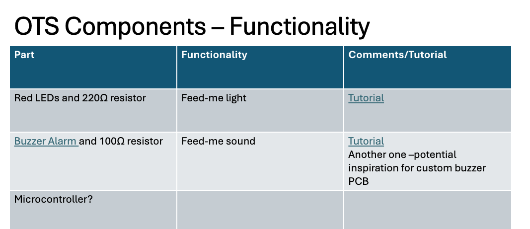
Here are my notes on what I planned on using for components (edits: I ended up not using the RTC and just coding that in; the Uno was a backup in case the PCB didn't work; I ended up using a 5V battery instead of 9; and also forgot the put my temp sensor in this table).
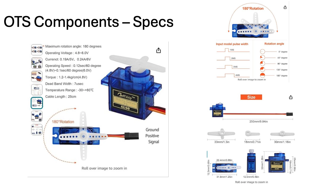
I had no idea how a Servo motor really worked and this was key to visualize for the waterwheel I would be making to dispense food..
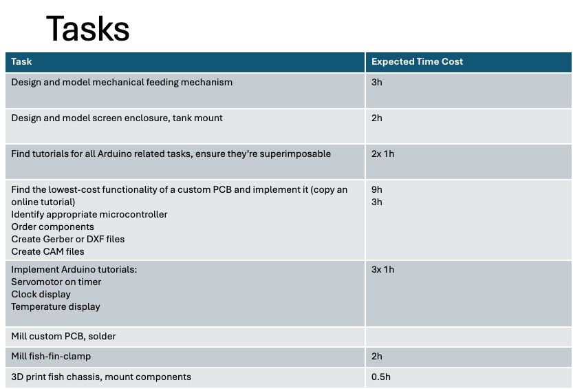
Thinking back to my PM exposure in machine week, created this task list to approximate how I'd be spending my time (this was ultimately pretty inaccurate, but a good start).
I started my prints for the two sides of the fish (see CAD above), and realized they'd be taking 6-7 hours each, so I didn't have much time for iteration.
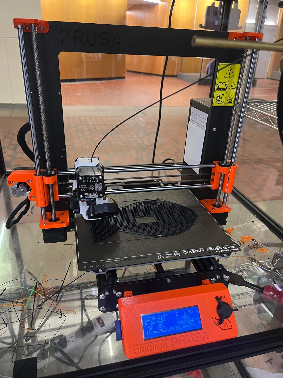
Shoutout Bobby for access to the science center printers!
At the same time, I was redoing my schematic (which, as mentioned in an earlier assignment, took me 5 hours...)

I wanted to make this out of aluminum for the subtraction part of the assignment, but couldn't find the right kind of block or the tools to mill it, so I 3D printed instead.
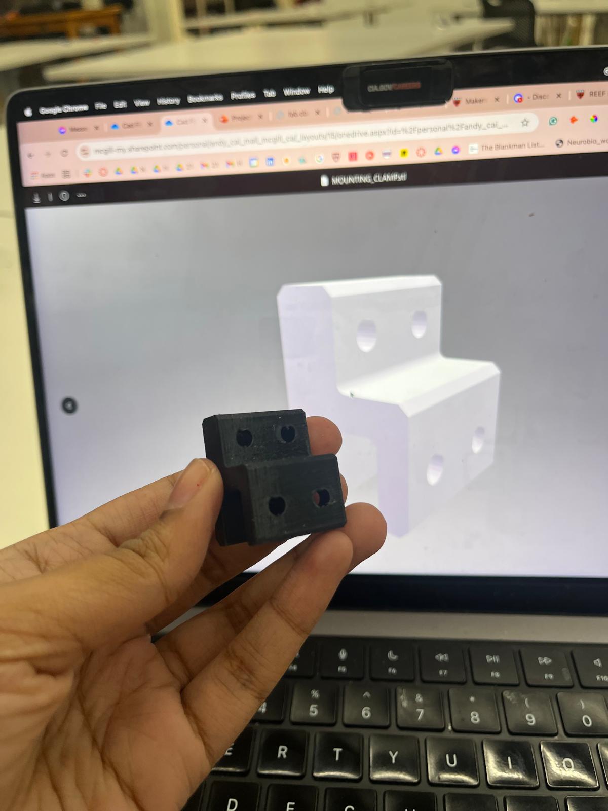
Mounting clamp design for alumninum milling
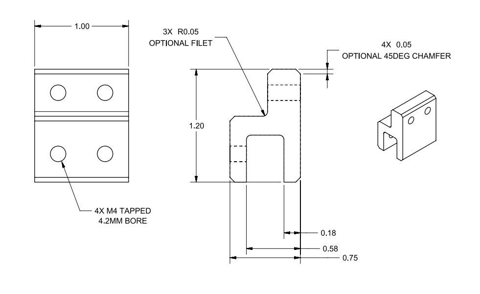
3D printed mounting clamp
Realized the two fish sides needed some way to stick together, so 3D printed these pins. Also not shown - laser cut an acrylic screen for the OLED.

Woohoo! I already had my PCB done so it was time to wire. This was HARD and SO time consuming but luckily I did not fry anything and had lots of help from Anthony + Nick + Quentin with soldering + wiring the PCB. It looked great in the end.
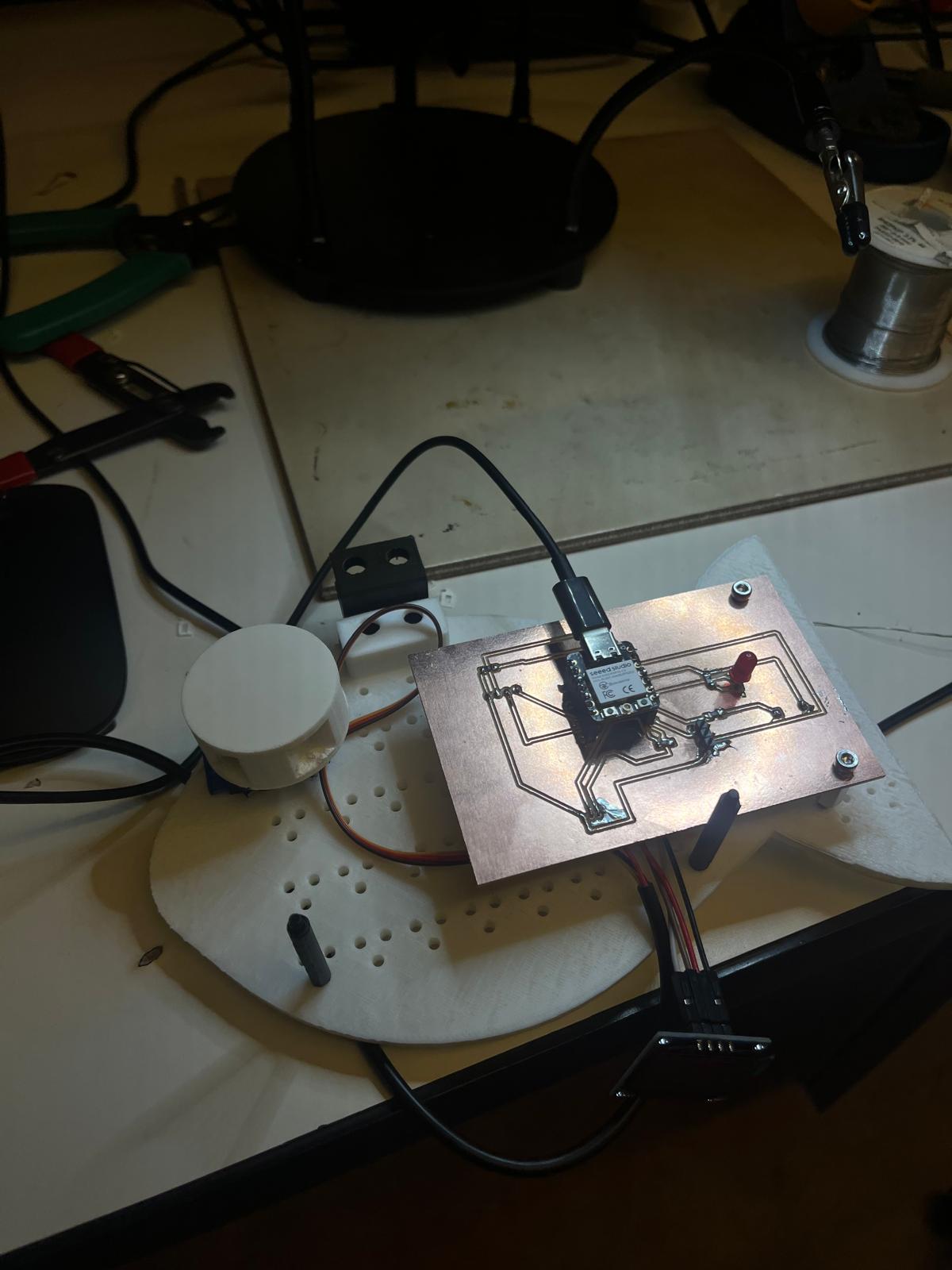
I had 3D printing the wrong dimensions for the mounting clamp, so Sam graciously help me make some adjustments (we melted + drill-sanded off the plastic of the tank to make it fit).
Here's the final PCB with the components and wiring! I ended up hot gluing the waterwheel to the Servo fan, which was not optimal, but at this point it was 5AM so I really needed something functional.

Here's what it all looked like in the end at Demo Day..
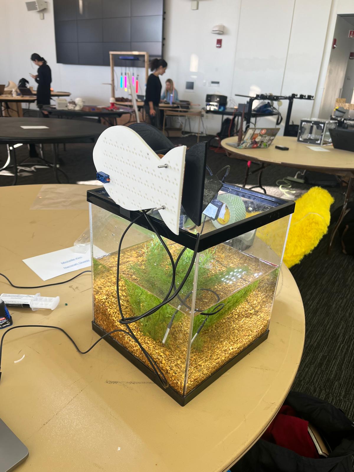
The completed smart aquarium
A photo with Prof. Gershenfeld at Demo Day, who skipped me during demos because he didn't think I'd finish in time (admittedly, neither did I!).

I'm quite proud of how this turned out despite all my challenges, and getting super sick. I have a 3D printed shell, which includes a funnel that the food goes into before it enters the servo-controlled water wheel. A temperature probe pulls temperature (input) and the buzzer + light indicate whether it's too low or too high (output) with the code I wrote. The temperature is read out on an OLED that is protected from the water by a laser-cut piece of green acrylic. I mounted my custom PCB with nuts, bolts and spacers, and added pins for additional support with the mounting clamp. I used the XIAO ESP32C3 and it worked perfectly for this. I did a ton of testing and tuning to realize some of my soldering was off so I strengthened connects / carved them out with an X-Acto knife. I also added a bit of wiring for the OLED so that it fit into the space I made on the front of the fish form-factor. I'm really happy about my final project, and extremely grateful to Leo, Gail, Joe/Jeff from the REEF, Quentin, Nick, and especially Anthony for all their help throughout this entire process. I learned so much!