The journey:
I have decided to make a (mini) vending machine for my final project. I'm not really sure why this came to mind, but it was actually my first idea, and it honestly just stuck. I like that it incorportates both mechanical and electronic components. In reality, vending machines get on my nerve every time I use them. I'm sure this one will also bring me a fair share of frustration, but I imagine it will be much more rewarding.
Planning and Brainstorming
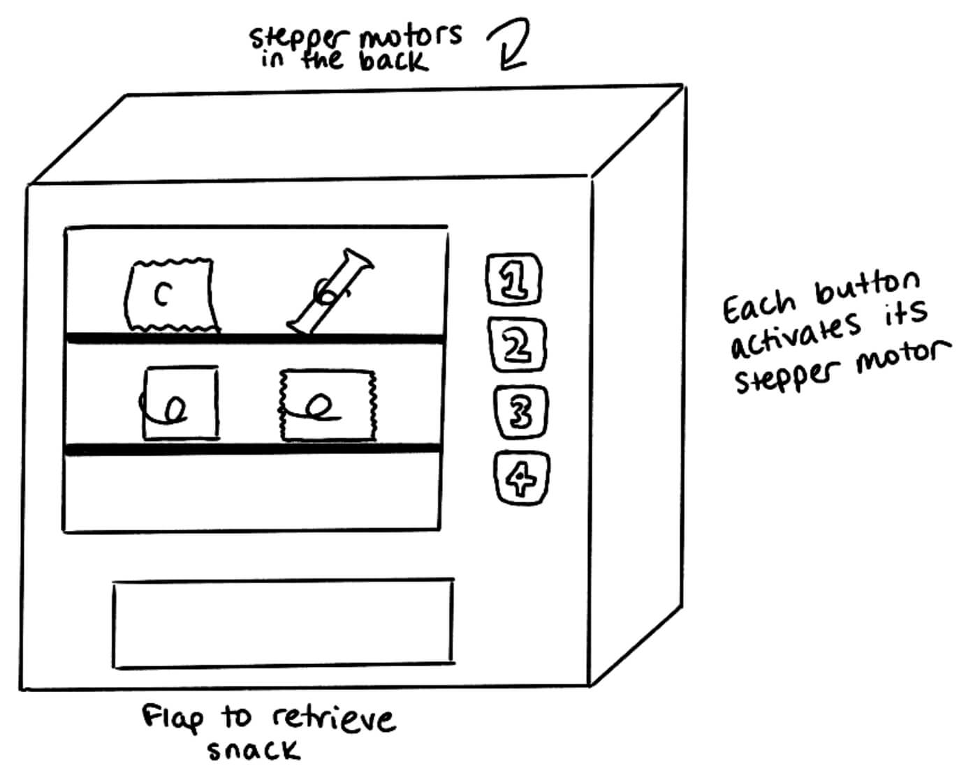
My design will be different than your average vending machine. First of all, it will be much smaller. It has to be light enough that I can physically carry it. It will therefore have 2-4 snack options only. I also want the design to be as simple as possible.
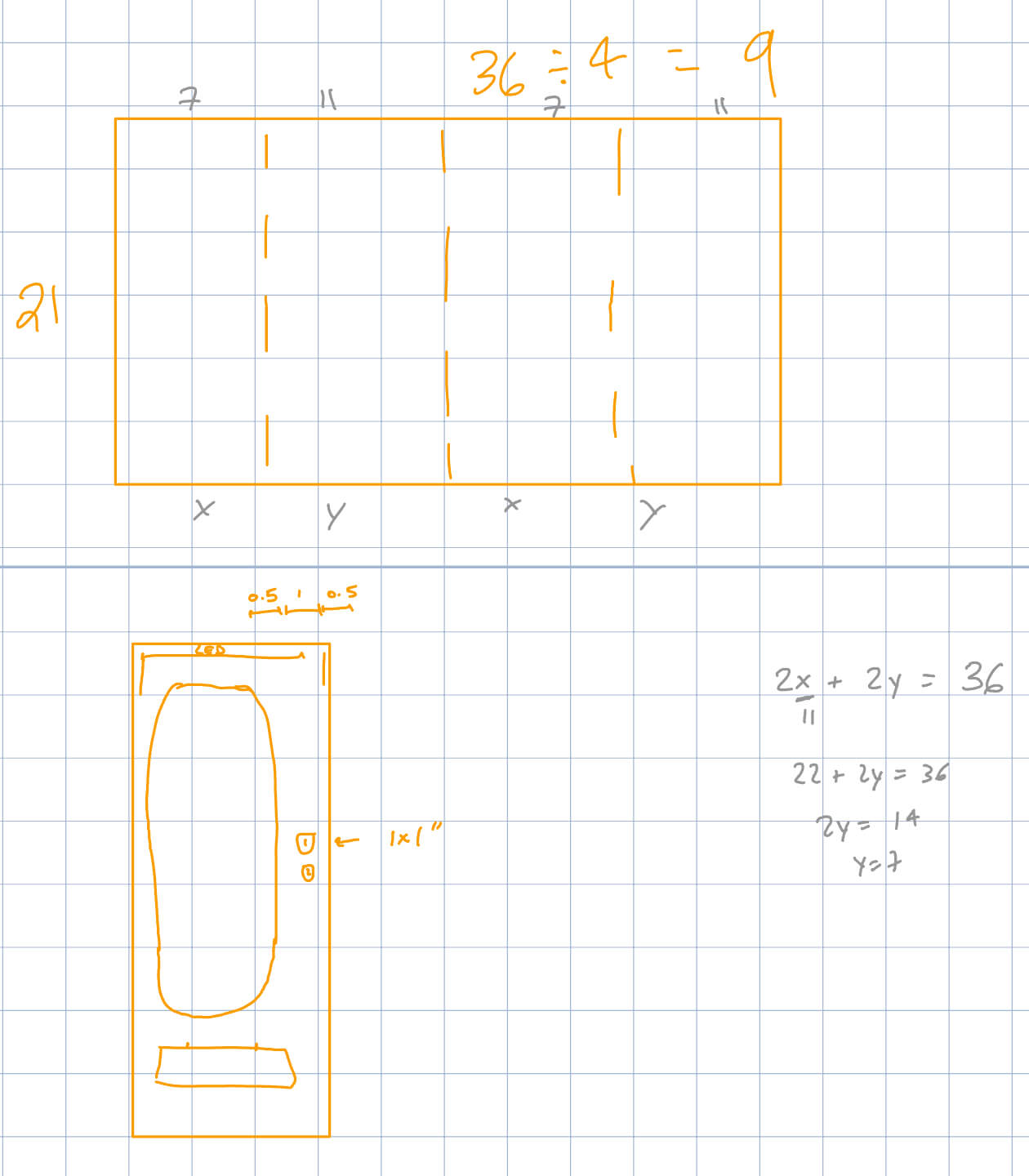
Here is my initial sketch:
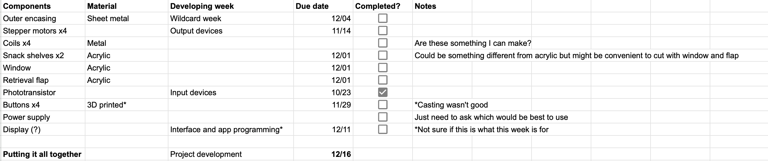
And here is a schedule for finishing everything on time:
Everything but the Electronics:
As the project deadline approached, the idea of 4 buttons seemed a bit too ambitious. I preferred to have a neat looking vending machine, so two buttons was more realistic.
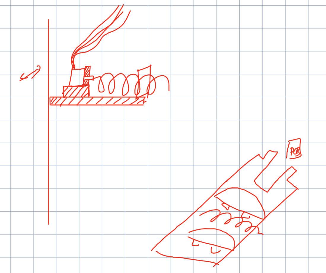
I also made a very rough CAD with no real measurements just to see what details I needed. I used it to plan how my integration and wires were going to go.

This showed me that I need to have:
- Hole for power supply
- Side holes in both platforms for the wires to pass through
- Holes for buttons
- Crawl space for the wires
At this point, I still was not sure how I wanted the back door to be. I couldn't fold all 4 sides because we need to still be able to access it from the back to restock snacks, fix electronics, etc. Perhaps keep that face separate and add it via hinges later? In that case, I needed to look into how to put hinges on metal, and how to drill into metal in the first place.
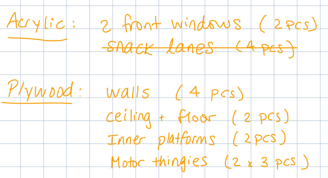
I had ordered (what I thought was) a 1/8" sheet of aluminum, and even had it sitting pretty in my living room for about a week. When it was finally time to cut it, I realized that I had actually bought a sheet of aluminum composite. Apparently, there is a massive difference, and aluminum composite cannot go in the laser cutter. Cue my panic. This was on Sunday (2 days until final presentation). I called Blick and a bunch of other stores, to no avail. I also asked Bill and Chris from N52 if they had any, and they only had scraps that were too small. I had been wanting to make it metal primarily so I could also use it for Wildcard week and hit two birds with one stone. But at this point, it was not worth it anymore. I had to shift away from metal for this project. My next material of choice was plywood. Here came a new list of sheet materials:
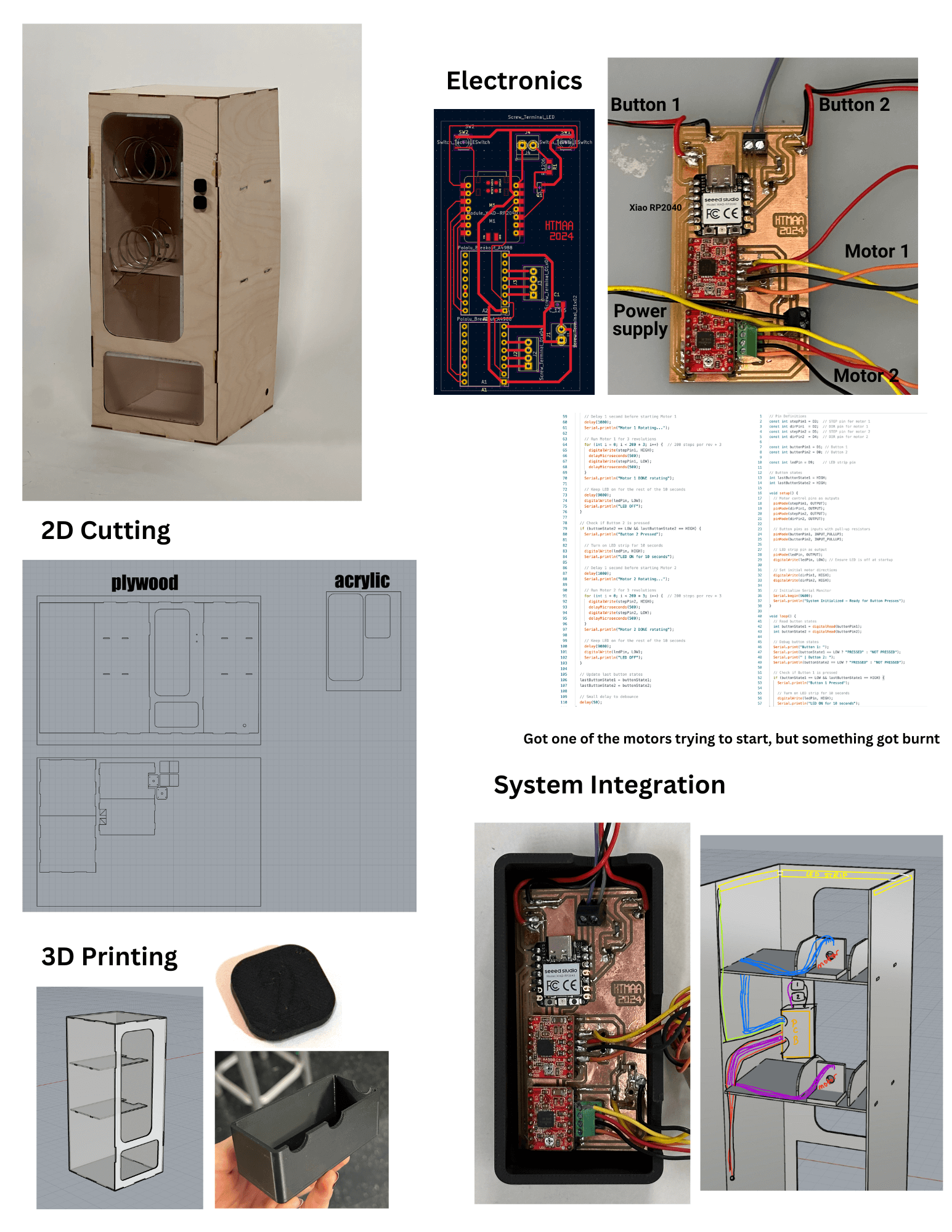
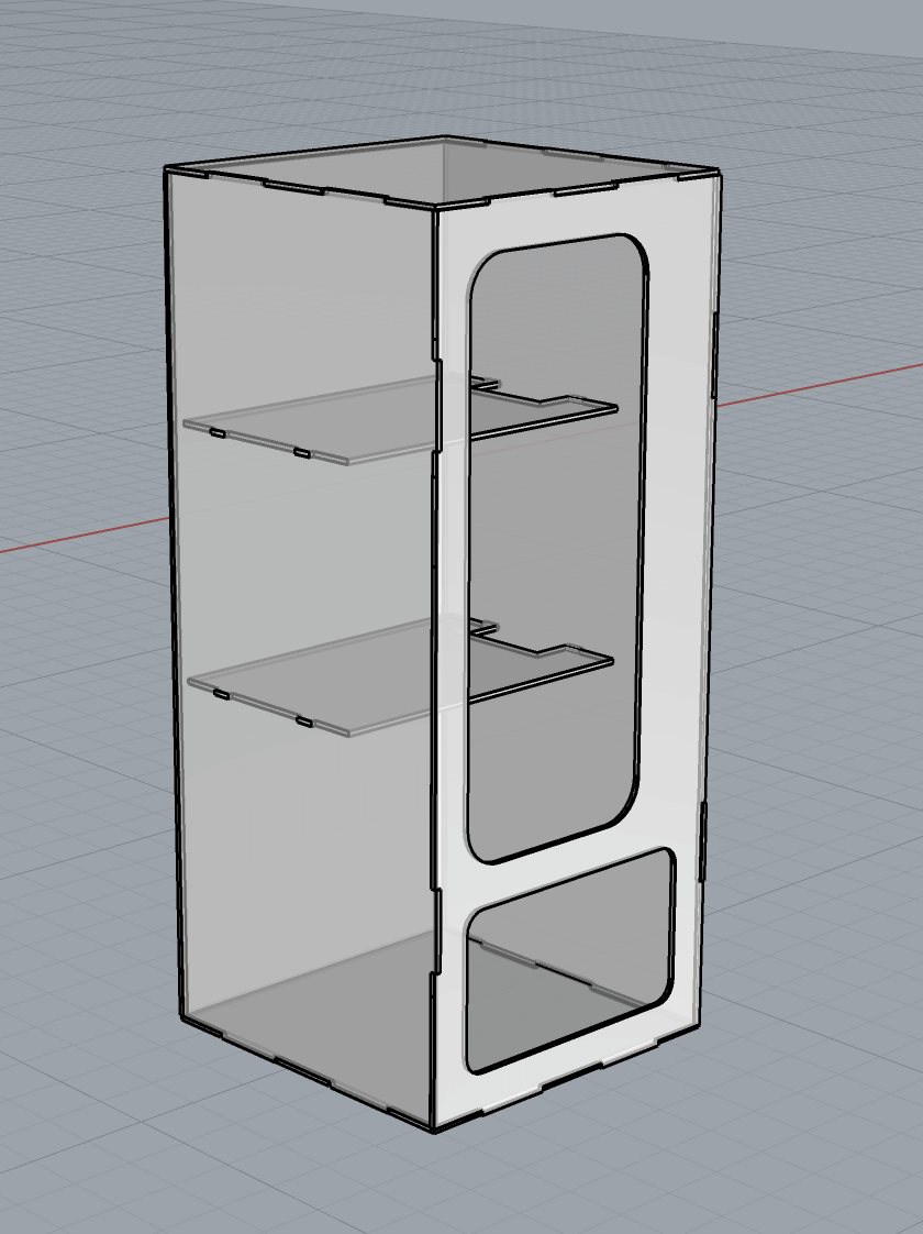
I re-CADed it with more detailed dimensions and made my cut file out of that:
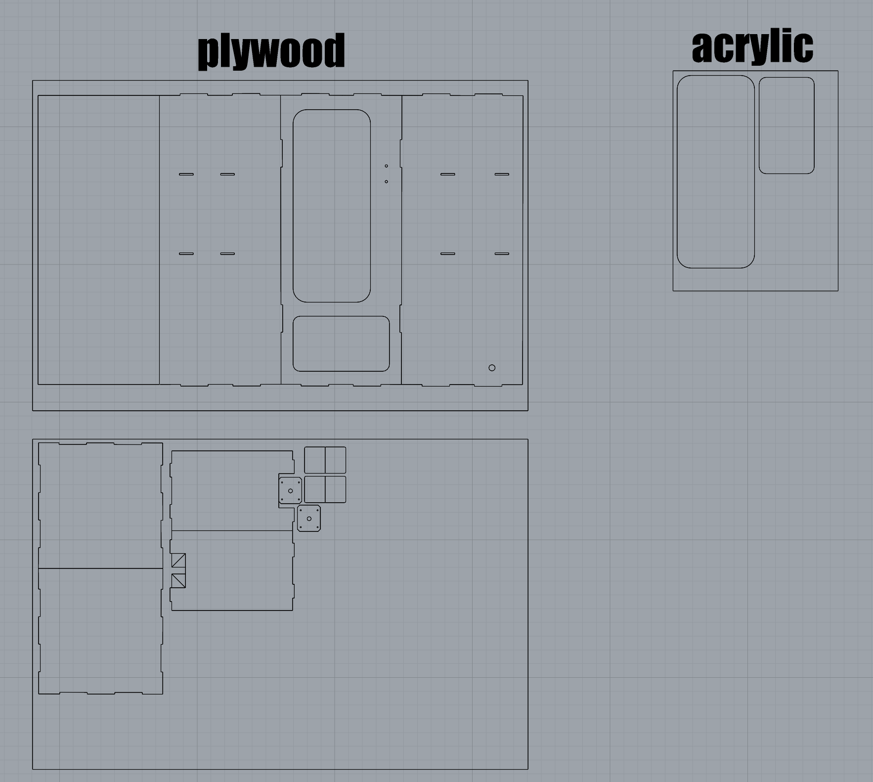
The acrylic sheet I bought online was great. Thank God I got something right. But my next big sidequest was finding plywood. I needed about a 24x36" sheet and a half. I went to the Architecture Woodshop, and Chris was happy to sell me one large sheet for $25. He also cut it up for me into 2x 36"x24". Unfortunately, it was so non-flat that Chris even remarked "I'm sorry you have to pay for THIS sheet." Just last minute things, I guess. You use what you have available. Just so we're clear, this is how much bend I'm talking about:
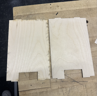
After laser cutting, I sanded the pieces to get rid of the burn marks. Here is a before and after:
For some reason (maybe the power was too high, even though I used the presets for the material and thickness?), white appeared near my acrylic cuts.
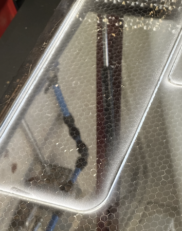
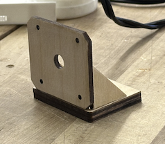
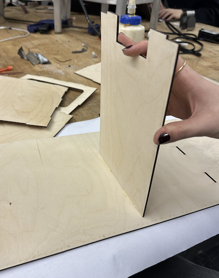
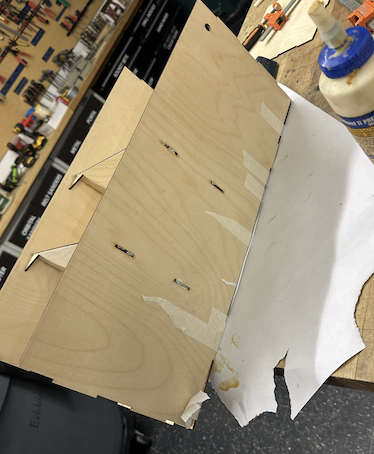
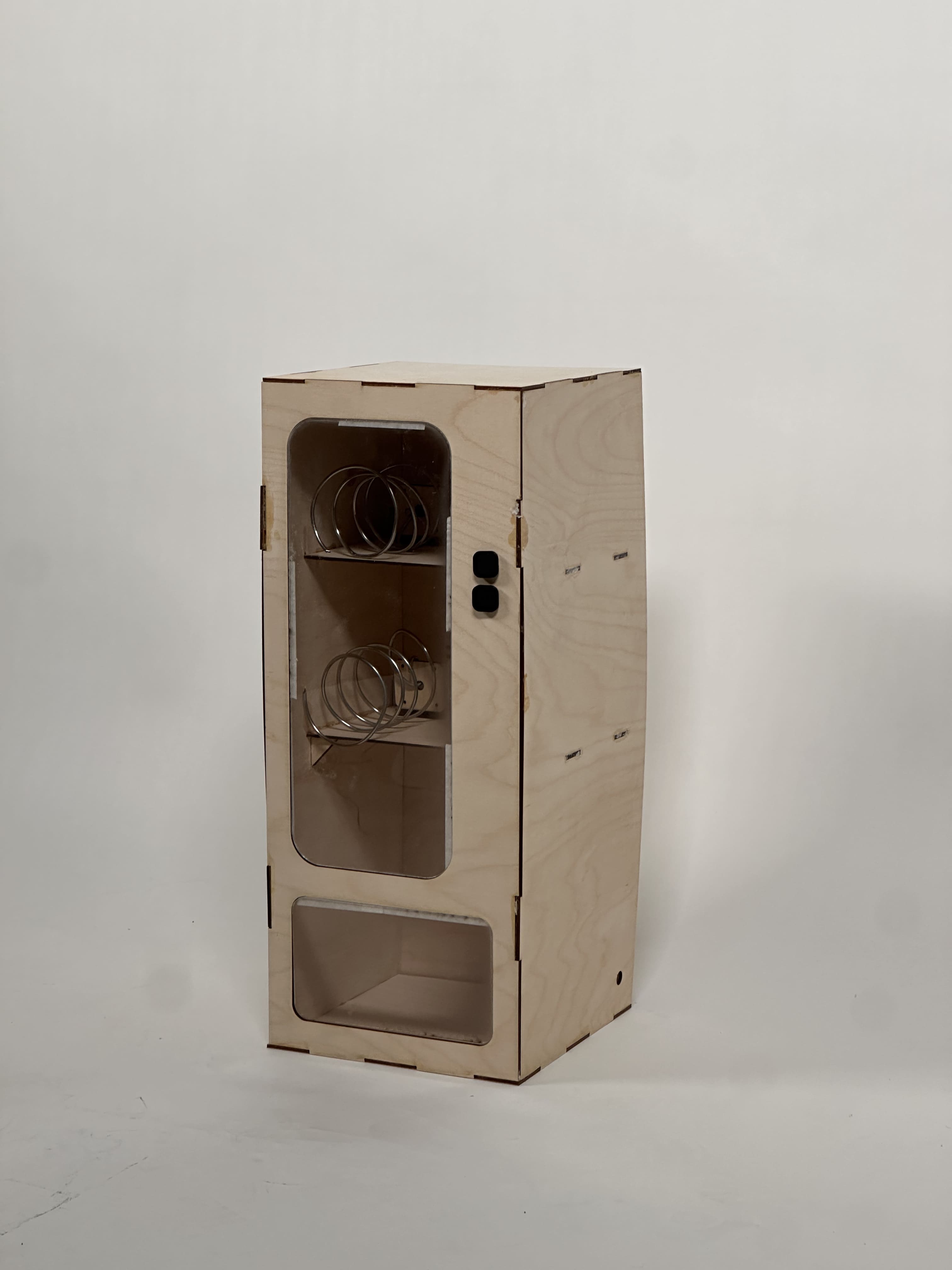
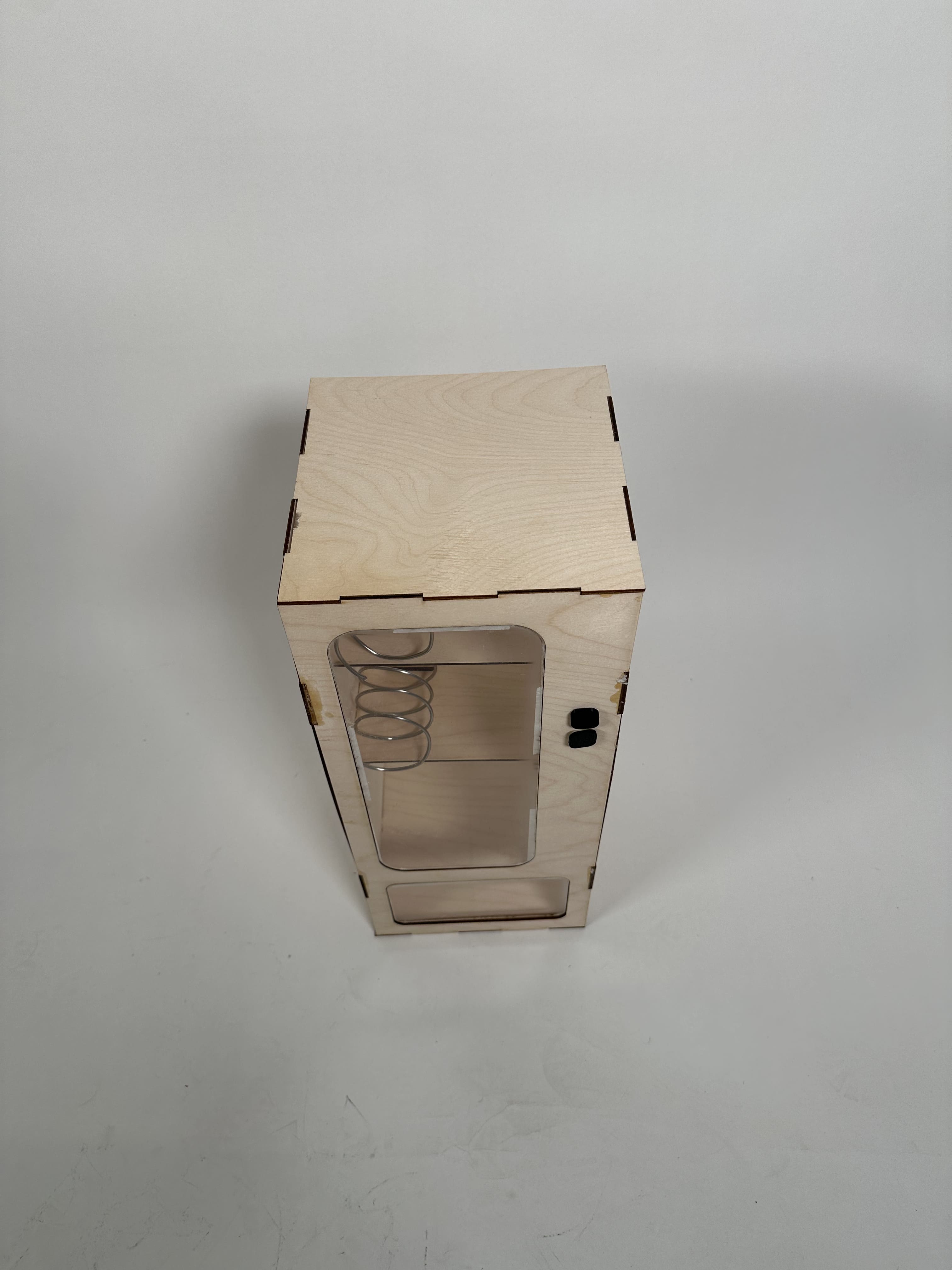
I washed it off with water and a paper towel, and most of it came out. Next came assembly.This was so much more time consuming than I thought it would be. I forgot how long wood glue takes to dry, and I used too much of it in the beginning, making it actually take ages to dry. Pieces kept falling out of place because I did not glue them properly. Only this first mini assemble was easy XD:
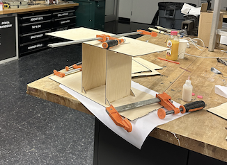
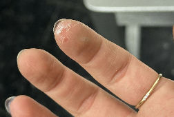
At some point here, I got impatient and started using superglue. It worked pretty well for the smaller joints but not the big ones like the ones between the walls. I also thought I could get away with not wearing gloves but I got superglue on multiple fingers and it was just so not worth it.
The reason I did not clamp the pieces was that it felt like the pieces were literally going to snap under the pressure. So I relied a lot on right triangles to join together different pieces.
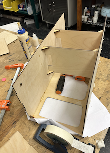
Then, I finally thought of using tape. This was a gamechanger. Highly recommend tape to hold pieces together while gluing. Do not recommend superglue for plywood.
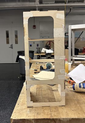
I also added a piece of tape here to make the bottom acrylic hinge inwards.
The Electronics:
This whole journey started on my iPad when I was sketching out the pin connections for my project. I knew I wanted to control two motors and have two buttons trigger them, with a little twist: when I pressed a button, the LED strip would light up for 10 seconds, and after a 1-second delay, the corresponding motor would spin 3 full revolutions. I had a plan, but I also knew things wouldn’t be as smooth as I hoped. I was right.
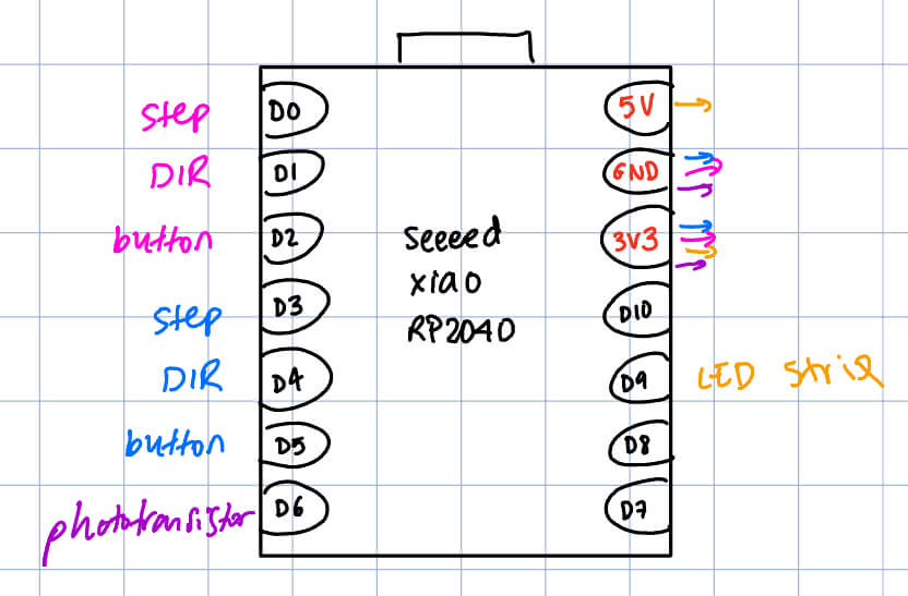
I ended up changing the pin assignments so that they work better for the tracing, but this was stil helpful to see how many pins I still had free and what potential things I could or couldn't do.
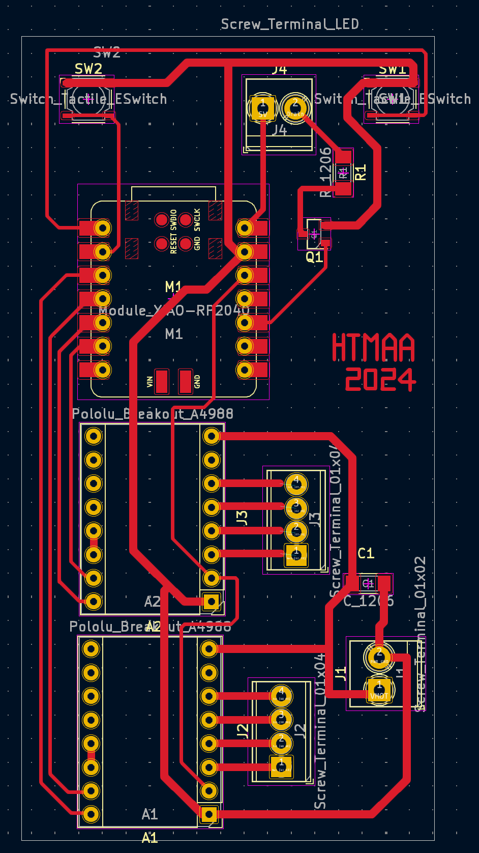
I moved to KiCad to design the PCB schematic. I connected the motor drivers (A4988), buttons, and LED strip.
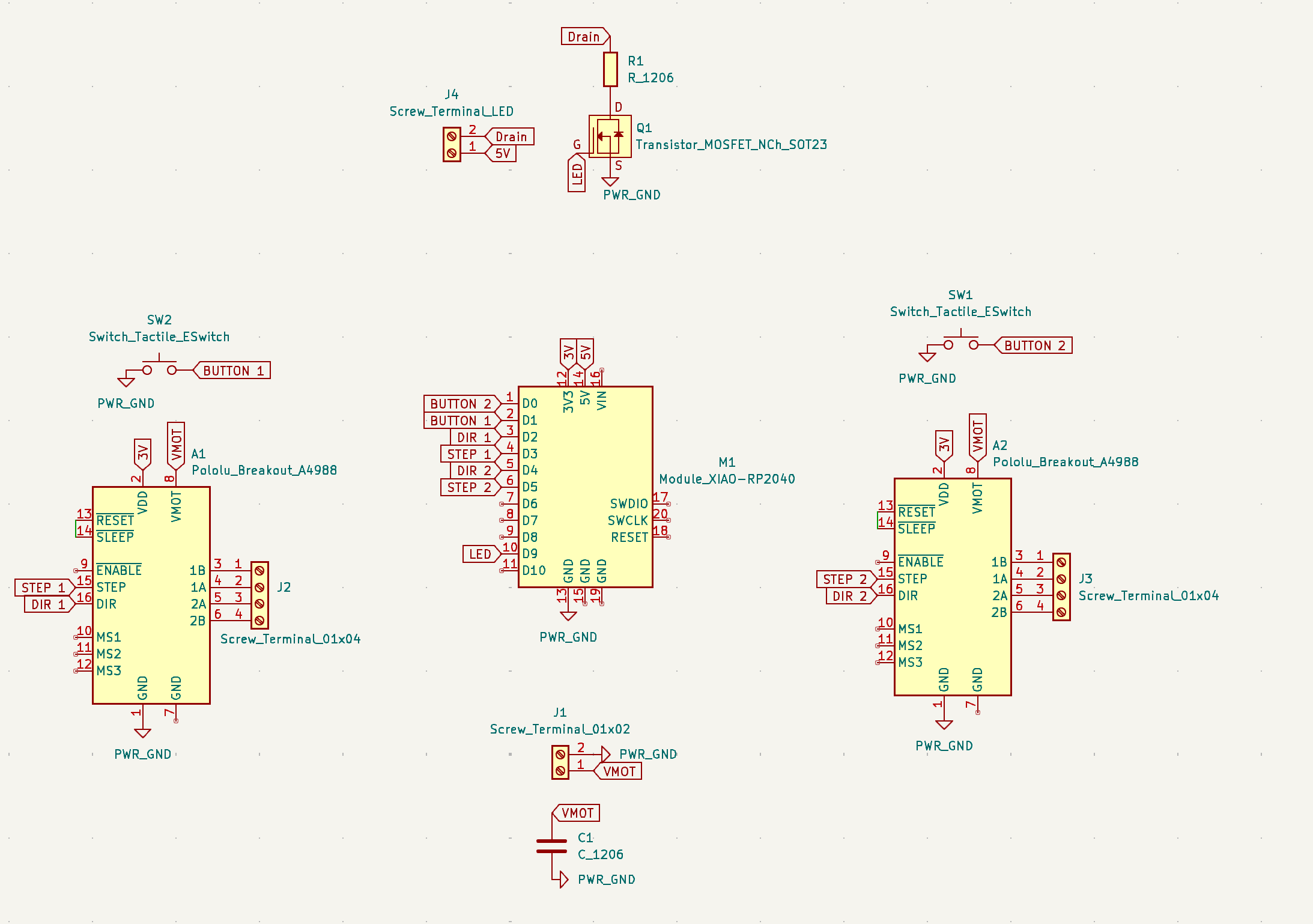
At first, I placed the traces for the motor driver outputs to a terminal block. I remember zooming in and triple-checking the labels: A1-1A, A1-1B for the first motor, and A1-2A, A1-2B for the second motor. They should come up with clearer names for these!!
DRC errors started popping up during tracing. “The routing start point violates DRC,” even though the starting point is literally my pin on the Xiao. I had to tweak the trace clearances, which took a bit longer than I expected.
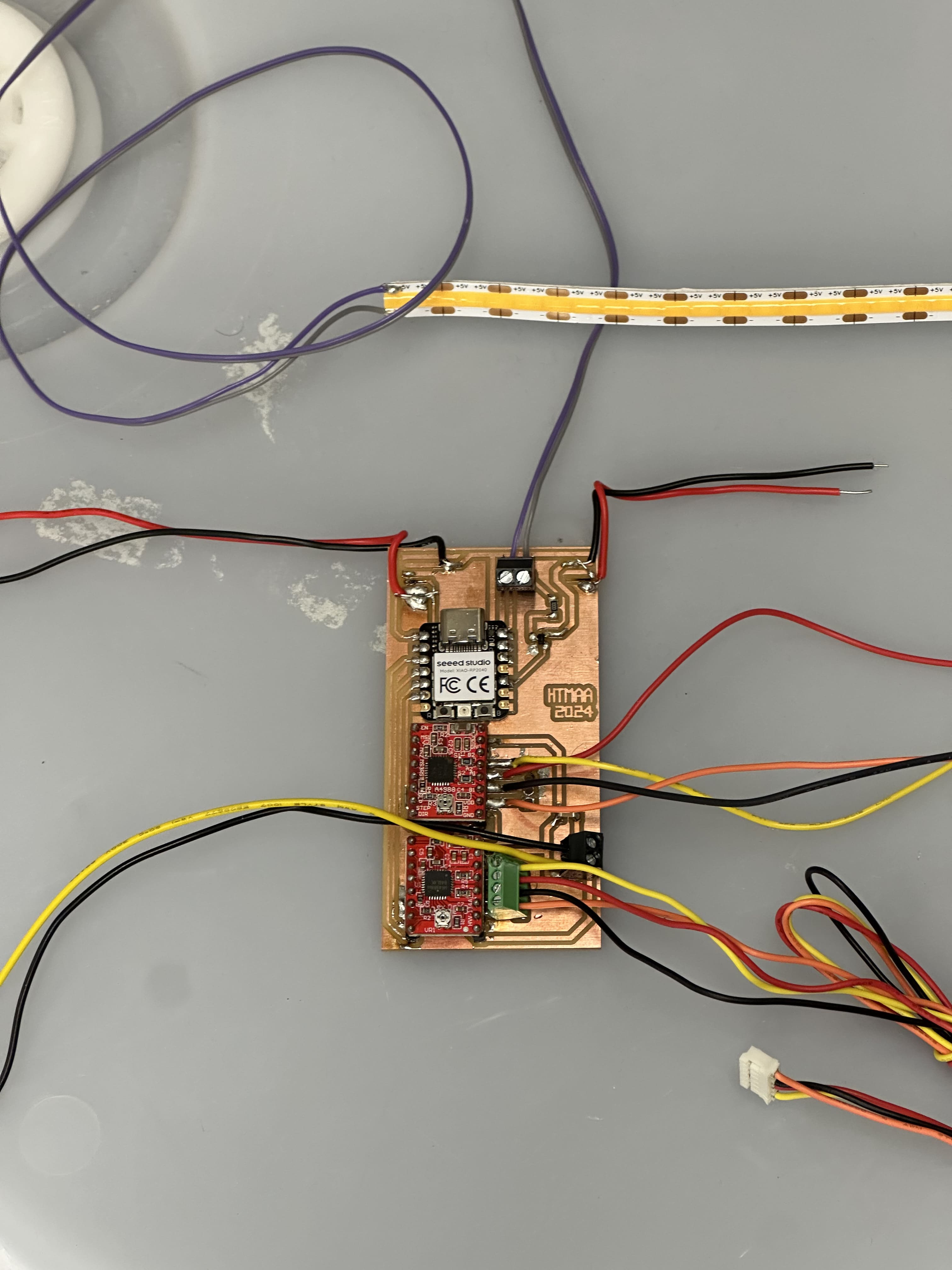
I exported the Gerbers and went to mill the PCB. Everything seemed fine—until I checked the milled board and realized that a bunch of traces were connected where they shouldn’t be. The separation wasn’t milled for some reason. I manually cut the copper with a sharp knife. I held my breath while doing it because I didn’t want to ruin the board. When I checked with a multimeter and saw no continuity, I was relieved.

Now came what was the hardest part for me. The bane of my existence for the past couple of weeks: soldering. Soldering things that were not wires onto the PCB was fine. It used to be really difficult for me to solder the motor drivers, but they were (almost) easy breezy this time. What I struggled with was the terminal screws and their corresponding wires. Soldering the terminal screws was challenging, but the problem was that they kept ripping off my copper.
It was also challenging for me to solder the buttons. First of all, the metal pieces on the button were tiny, and I kept accidentally melting the plastic around them. I imagine this would have been better if I was soldering them onto the PCB, but I did not have the space to put them where they needed to be with respect to the vending machine all on one single PCB. So I tried soldering wires onto said tiny metal parts. I ended up switching to bigger, easier-to-solder buttons when I realized I probably was not going to be have time to even put my buttons and PCB in the right place.
The coding part was more familiar thanks to Output Devices week. I wrote the logic: When Button 1 is pressed, LED turns ON for 10 seconds. 1 second after press, Motor 1 spins 3 revolutions. (Same for Button 2 and Motor 2.) I added Serial Monitor messages to help me debug. “System Initialized - Ready for Button Presses” would let me know the code was running, and the button presses, motor starts, and LED statuses would all print to the serial monitor.
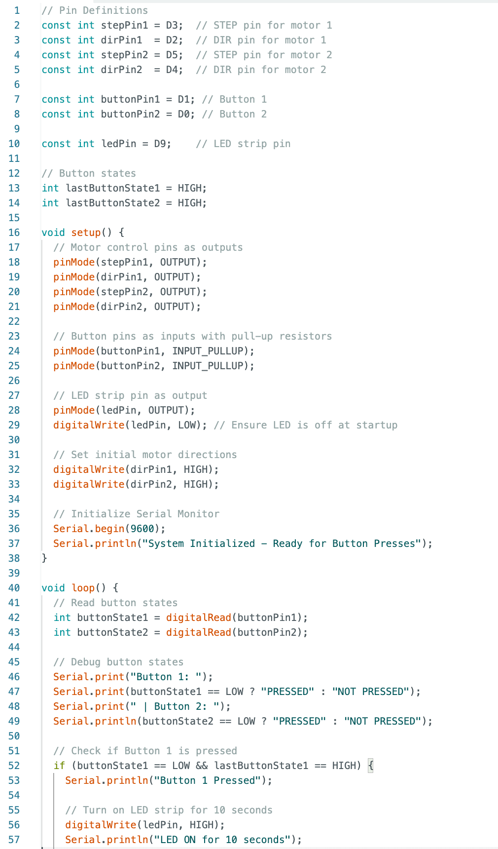
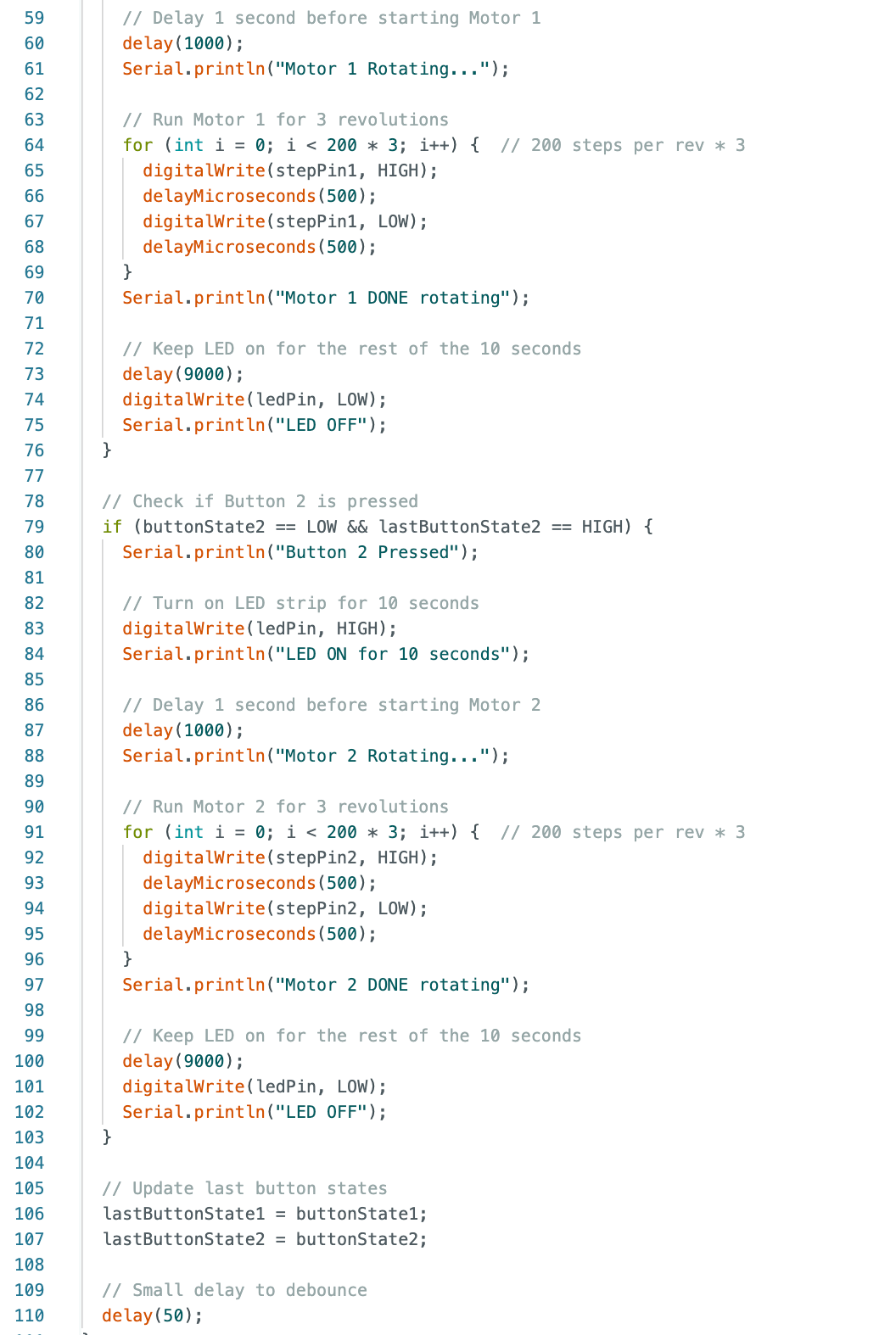
Here’s where things got… interesting. At first, nothing worked. The LED turned on immediately, even though I hadn’t pressed any buttons. I added even more Serial Monitor debugging to print out the button states. That’s when I realized the buttons were being read as LOW (pressed) all the time. I double-checked the wiring. Once I reconnected everything firmly, it started working. Pressing the buttons lit the LED and wrote in the serial monitor "Motor 1 rotating..." and "Motor 1 done rotating," but the motor was not actually spinning.
When setting up in the Media Lab, I tried again, with the help of someone from CBA section I think (?) whose name I actually don't know. But thanks to this person, I was able to figure out what was wrong. Thank you!!! I already knew one button was broken. I am sure it was soldered well and everything, it just was not working. I did just get it from a table in the shop, so it had already been used for sure. The other button was working. This person started yanking all my motor wires until one of them came loose from a screw terminal. "Aha!" she said. Also, by this point, we had gotten the motor to at least sound like it was trying to spin, but it's motor driver was heating up like crazy and we smelled something burning..
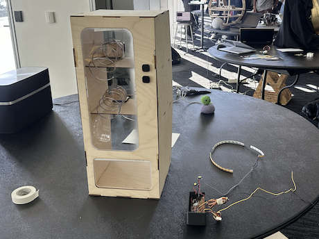
I connected the spiral, which I made by bending a metal spool on a jar, onto the motor with tape.
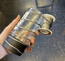
I originally tried soldering it on, but that did not work. The motor spinny thing is resistant to solder! Then, even though I did not have time to put the wires and everything into the machine properly, I still took some cute photos of it in the photo booth.
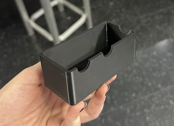
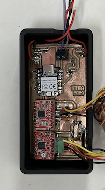
Also, I just remembered to mention, but I also had a couple of 3D printed parts! I printed a casing for my PCB that was meant to go on the front inner wall. It features holes for the wires to go out of.
My buttons were also 3D printed exactly to fit into specific holes in the front wall and press the actual button waiting inside (supposed to be flush against the wall from the inside). I used the design from Casting and Molding week.
In the end, I was very disappointed that my project did not work for the demo during final presentations. But I do know that I was so close! And in the end, I was debugging in ways that I did not walk into class on the first day thinking I will be able to do in a few months time. I improved tremendously, especially with my electronics skills, and I'm proud nonetheless!