For this week, I decided to wirelessly control an LED using the ESP32-C3 Xiao, an LED, and a resistor. The idea was to toggle the LED on and off via a web interface served directly by the ESP32-C3. Sounds simple, right? (Spoiler: It was not that simple.) It could be cool to someday turn my lights on and off from my phone. I needed an LED, a resistor to go with it, and a Xiao ESP32-C3. The PCB design was quite simple:
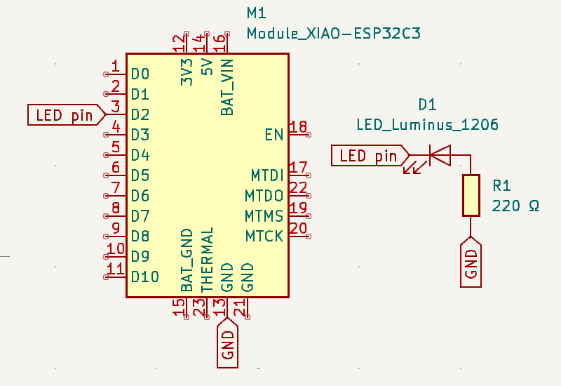
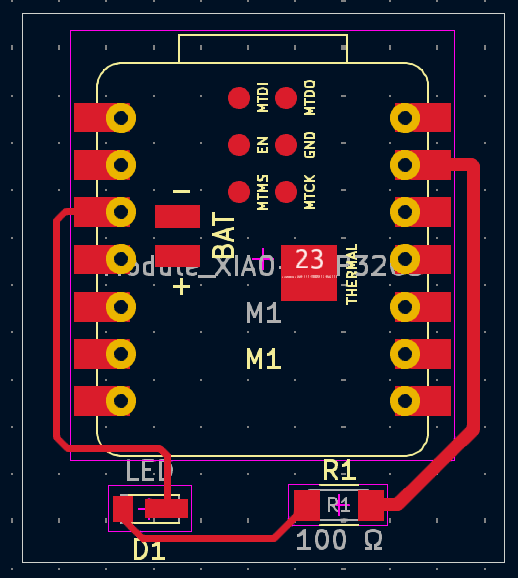
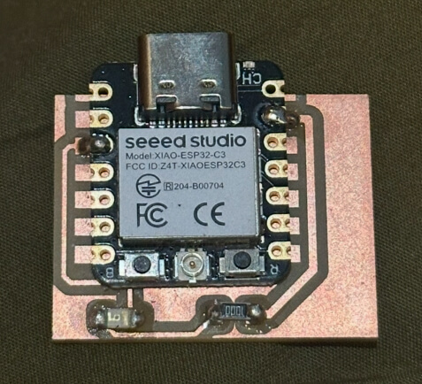
Next, I milled and soldered all the parts. A small challenge was figuring out the LED's polarity, but looking at the datasheet made it clear that the green side was the cathode.
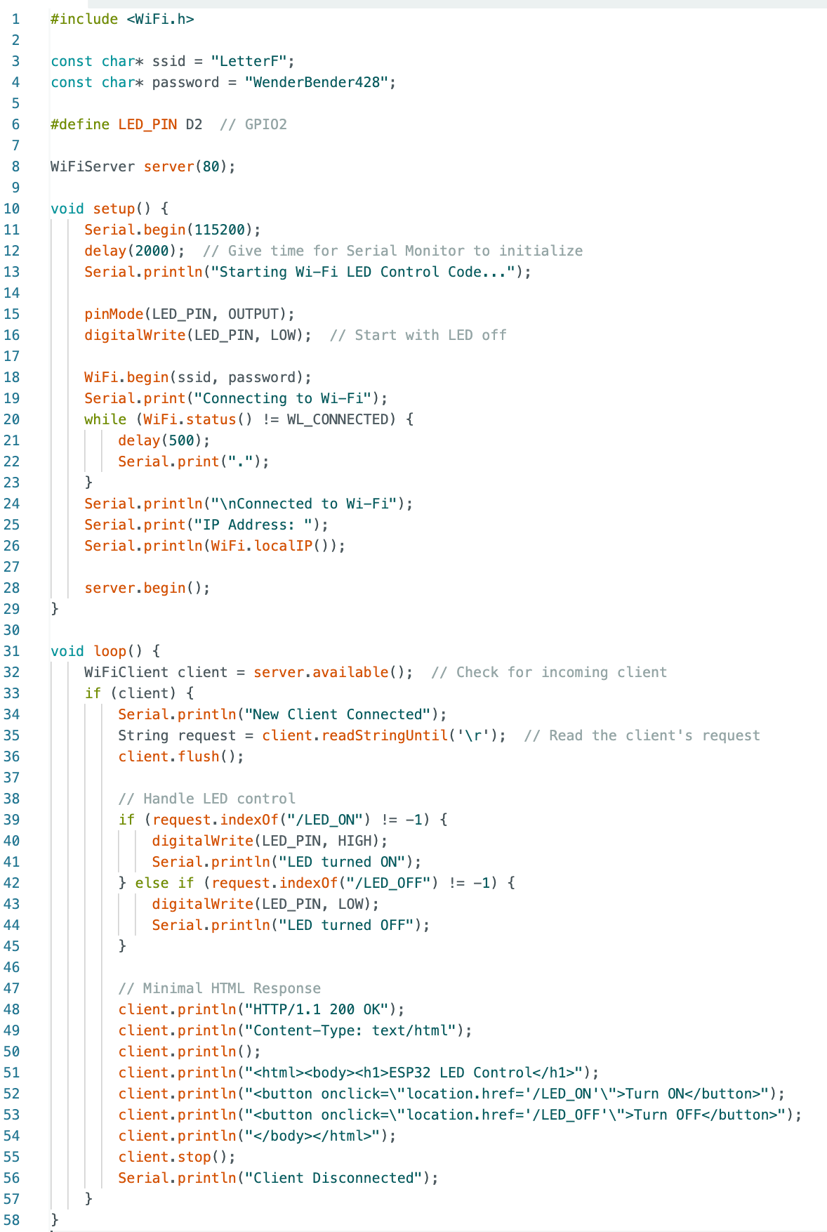
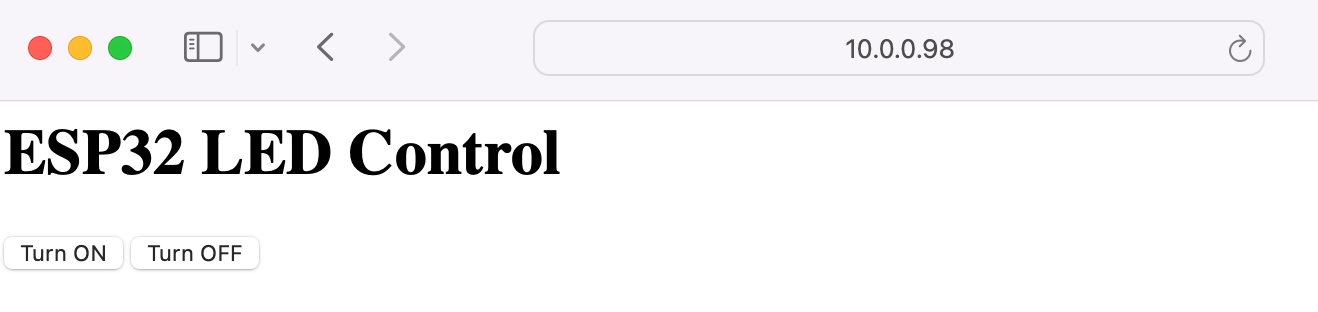
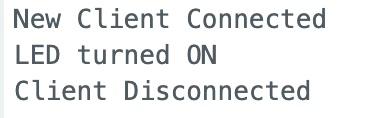
With the Wi-Fi working, I set up a basic web server using the ESP32-C3. It served a simple page with two buttons—one to turn the LED on and the other to turn it off. Clicking the buttons sent HTTP requests like /LED_ON or /LED_OFF to the ESP32-C3, and it would toggle the LED accordingly. I added debug messages to the Serial Monitor to make sure the requests were being received. Here is what the serial monitor says when I press "Turn ON".
Here’s where things got bumpy. The LED didn’t light up as expected, even though the Serial Monitor said the commands were received. I used a multimeter to discover that the GPIO pin wasn’t delivering the right voltage. Cue a series of tests:
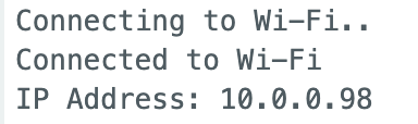
At this point, I started getting frustrated and had no clue what was going on. Everything seemed to be going wrong. I stopped being able to even connect my Xiao to the WiFi. It felt like I was making negative progress! I kept trying to unplug and replug the pcb back in, but nothing was happening. I later learned that you're supposed to keep it unplugged for 5-10s for it to actually reset. Like most things in life, that did the trick. Finally! It feels kind of stupid, to be honest, but I'm happy it works!