I’d already done the simple “LED on/off buttons” thing with a single-color LED last week, but now I needed to step it up. The plan was to get the RGB LED on the internet (again), create sliders to control the red, green, and blue values individually, and spice up the interface so it’s not just functional but looks good—like something you’d actually want to use.
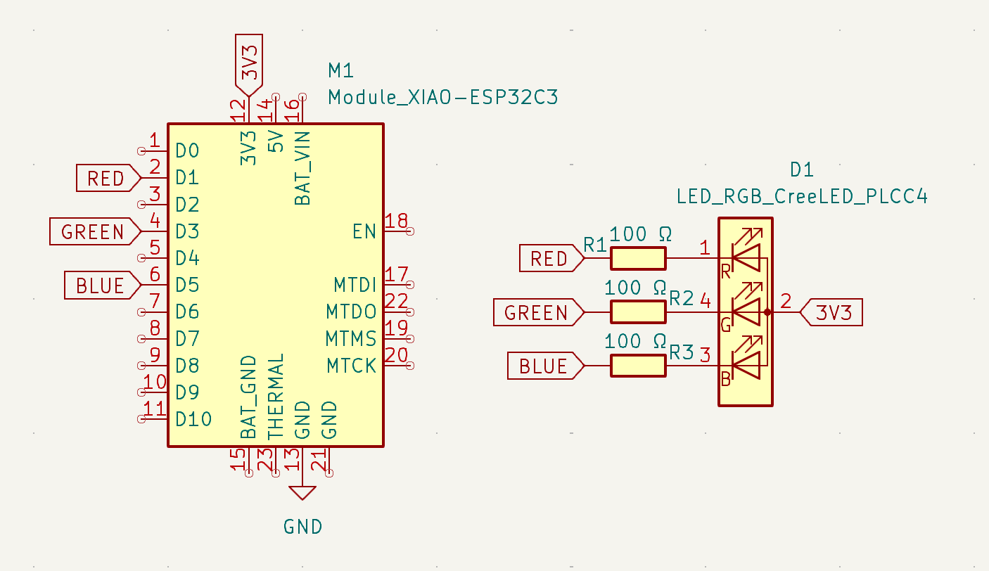
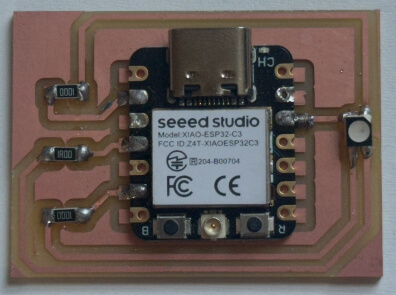
I set out to making a new PCB. My RGB LED is common anode, which means the common pin goes to 3.3V (not GND like last time), and I control the colors by sinking current through the red, green, and blue pins. Here’s how I wired it up:

Milling it felt like a breeze compared to the much bigger one for my final project. Soldering this was also a breeze compared to my final project!! I loved being able to just place things on the PCB and solder them on, without any holes or pins.
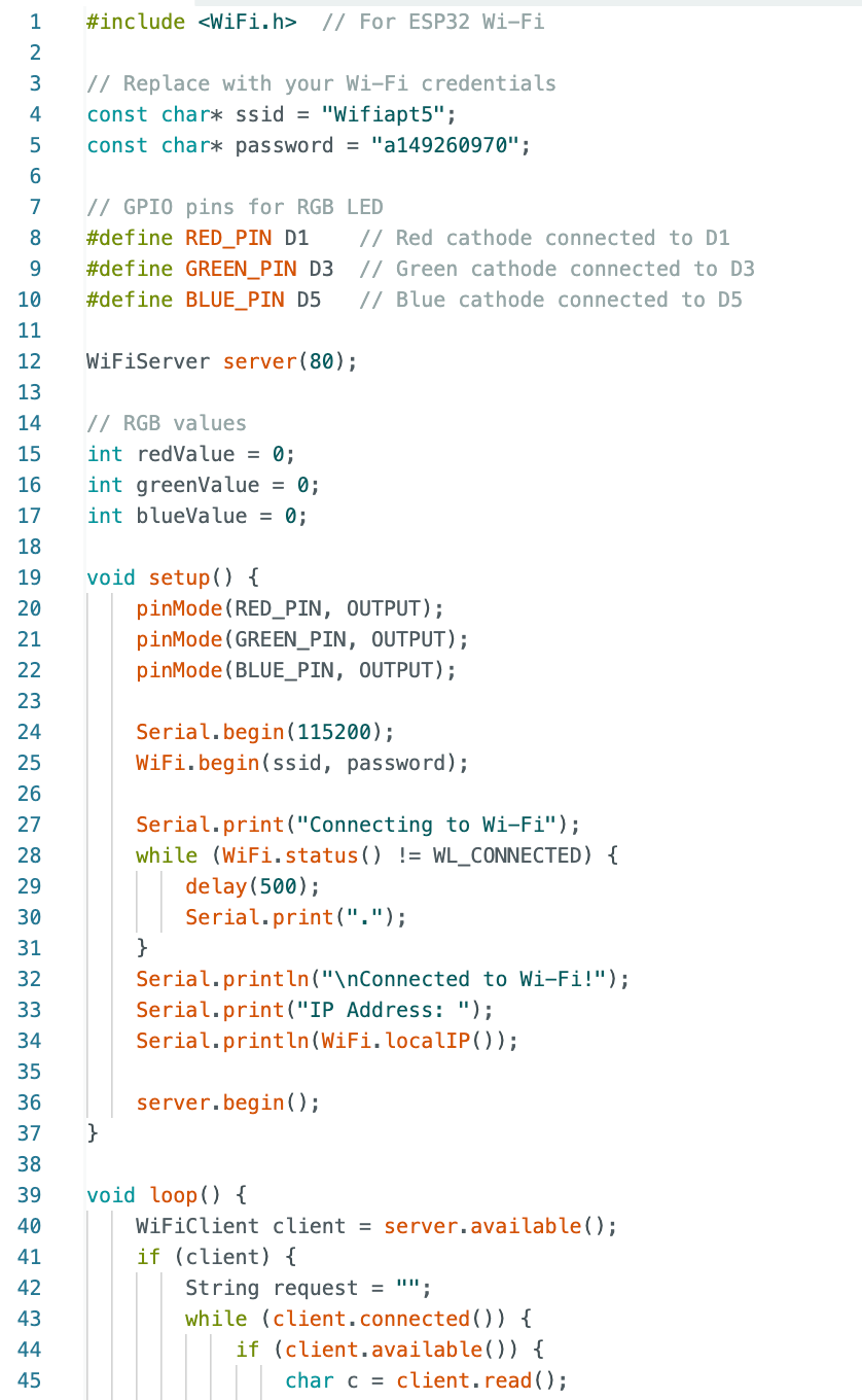
The next step was to bring it online. I started with the ESP32-C3 because it’s my go-to board for Wi-Fi projects. I used the same flow as last time: Connect to Wi-Fi, and serve a basic HTML interface through a web server. When you move sliders, the ESP32-C3 gets the new RGB values and adjusts the LED color with PWM (analogWrite).
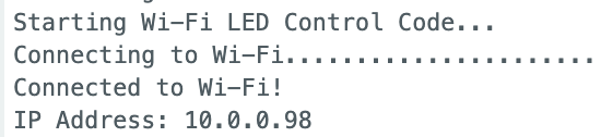
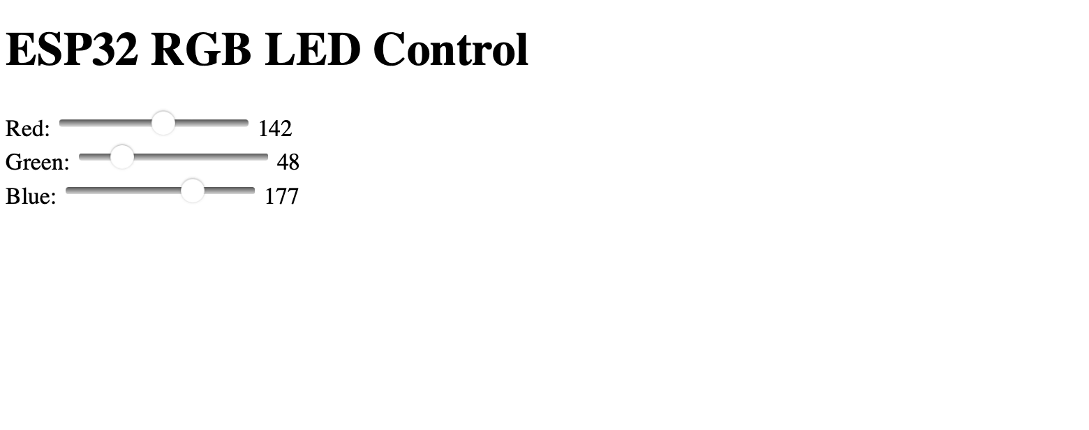
I put this IP address in my web browser. At first, I kept it simple—sliders for Red, Green, and Blue that sent the values to the board. The LED changed colors as I moved the sliders, and honestly, seeing it light up in yellow, cyan, purple (and full white) for the first time was so cool!
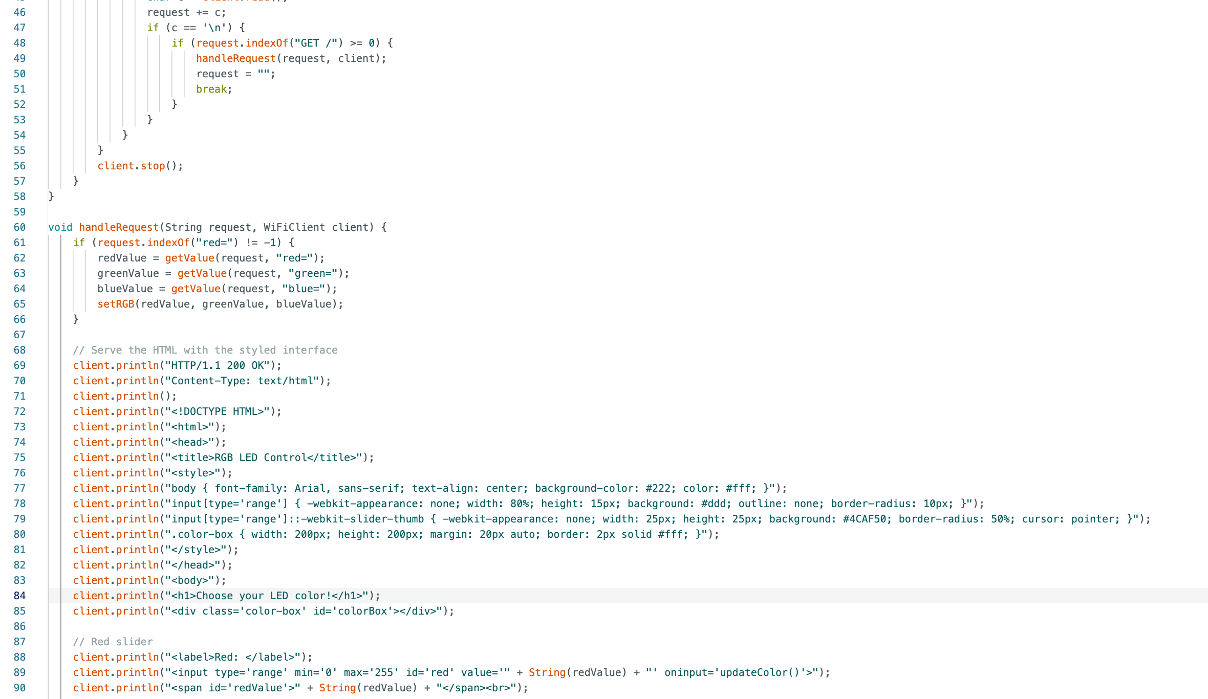
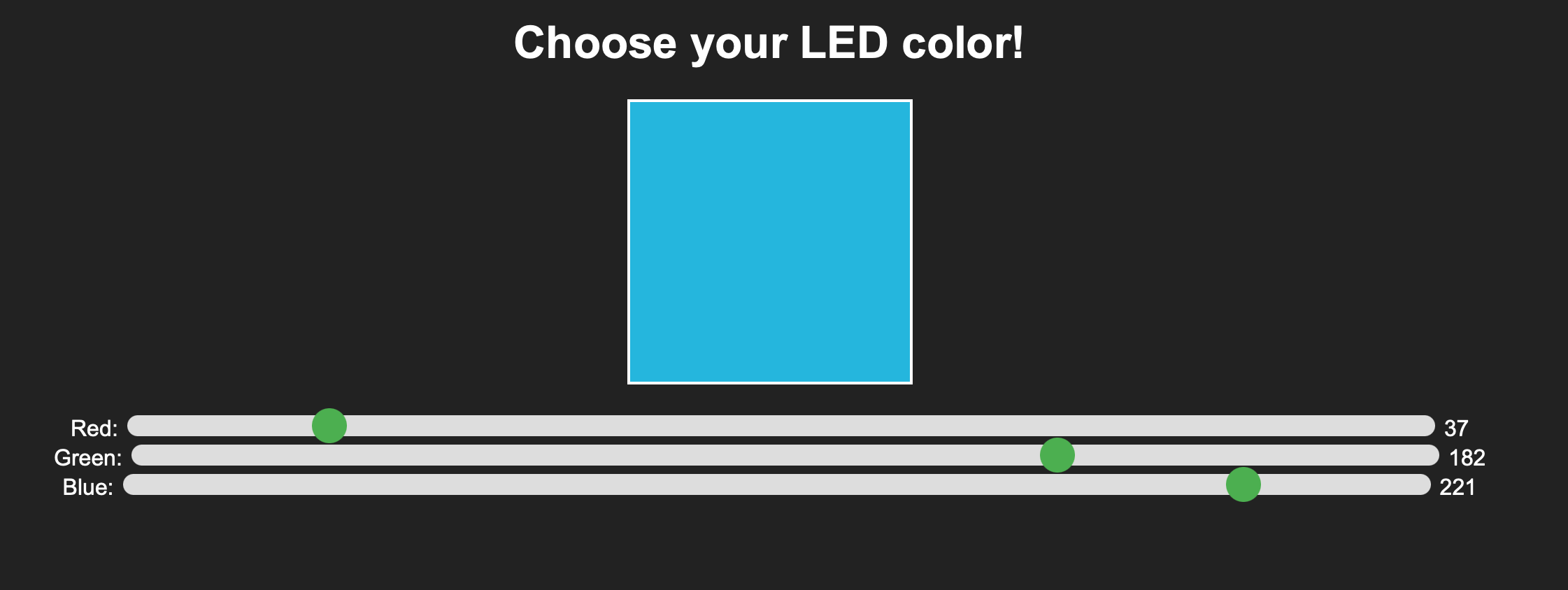
I couldn’t just leave the interface looking like some developer demo. This week is about interfaces, so I made it a bit prettier. I added a color preview box that updates in real time as you move the sliders. I styled the sliders with CSS—rounded edges, smooth animations, and a nice dark theme (it’s always dark mode in my world).
To reflect this on the LED, I had to do some debugging. I mixed up which GPIO pins were D1, D3, and D5 a couple of times. (Lesson learned: always double-check your pin labels.) My LED also wouldn’t turn on at first because I forgot how common anode LEDs work—LOW turns them ON, not HIGH. Smh. A lot of the debugging happened in the Serial Monitor, where I printed out the RGB values to make sure everything matched up. Here it is working!
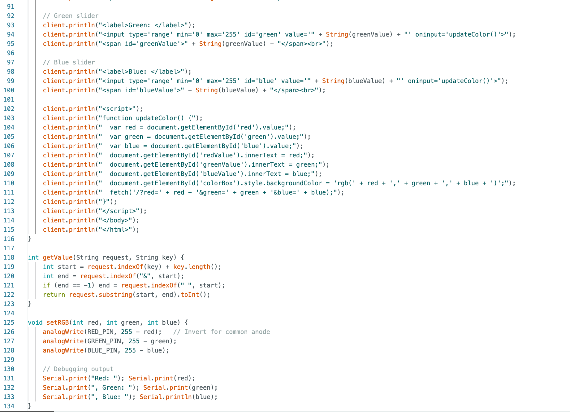
And this is the corresponding code: