As someone who has had extremely minimal experience in programming, I didn't know where to begin this week. I knew I wanted my weekly assignments to build up to my final assignment, but I didnt even know how a vending machine does what it does. I reached out to Niklas in the architecture section, and we talked a little about a few possible ways forward. We decided that an RP2040 mircoprocessor and keypad would be good to get started with.
Looking at the many, many pages of its data sheet, I learned that The RP2040 datasheet is long because it packs a ton of features into a tiny, affordable chip. Even the tiny pins can do so much and have so many components.
Our group assignment was also eye-opening. We were shown where to find the different electronics in the architecture shop, and we went over a few components and when to use what. We all downloaded Arduino IDE and learned the very basics.

After that, I compiled a list of the components I would need to make this happen.
After that, I was almost to start the simulation. My vending machine will probably have four snack options, and therefore four metal spirals that rotate. I decided to run the simulation with just one, for simplicity purposes. I don't imagine it will be too complicated to go from one working motor to four.
Here are the steps I followed:
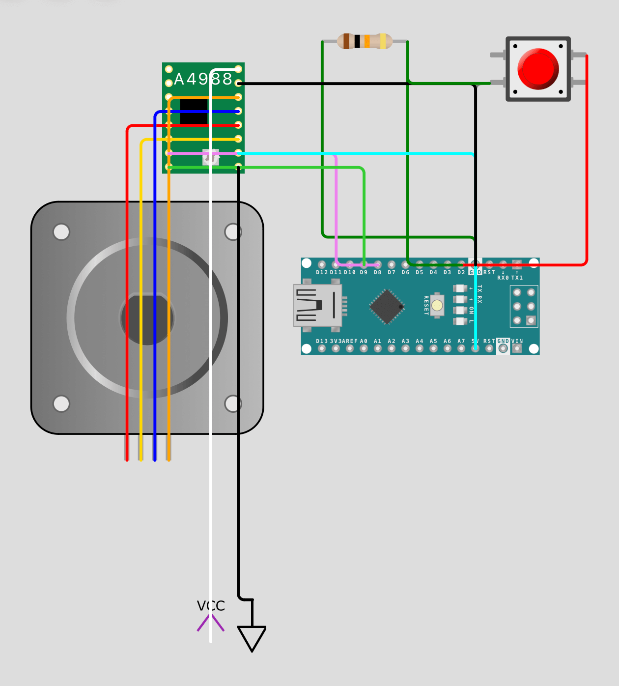
Next, I worked on the code, which ChatGPT helped me with. It did have an obvious error to me, but this is what I ended up with after fixing it:
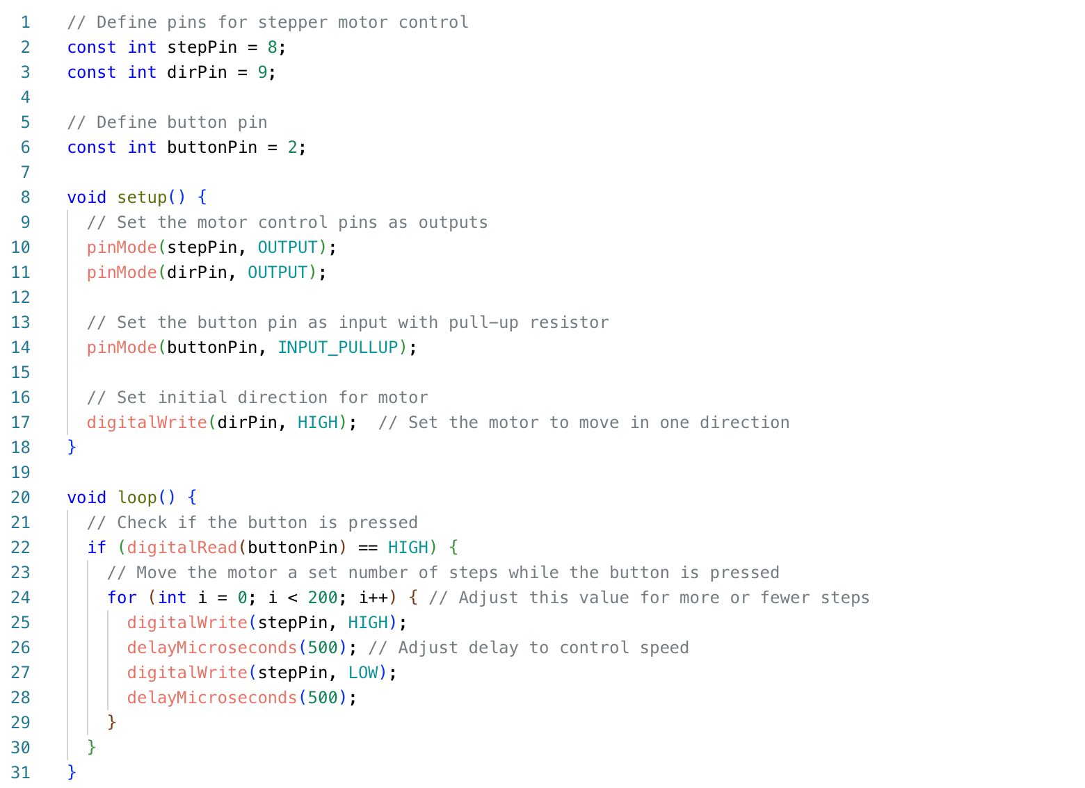
Unfortunately, nothing happened when I ran the simulation. I'm not too sure of my hardware connections, and I imagine that that's where the error lies.
I went to office hours, and Alfonso helped me compare my simulation to an already-existing Wokwi example. This helped me get it to work! I re-wired my circuit like this:
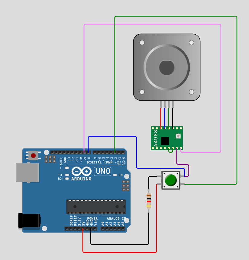
I also changed my code to the following:

Right now, the motor is stepping continuously while the button is held down. So the longer I hold the button, the more steps it takes. But I want it to move a fixed number of steps each time I press the button, regardless of how long it's pressed. To achieve that, I tried changing the code so that it only registers the button press once per click, and moves a fixed number of steps every time the button is pressed and released (i.e., on a button "click" rather than holding it down). I did this by tracking the state of the button and only moving the motor when the button transitions from "not pressed" to "pressed."
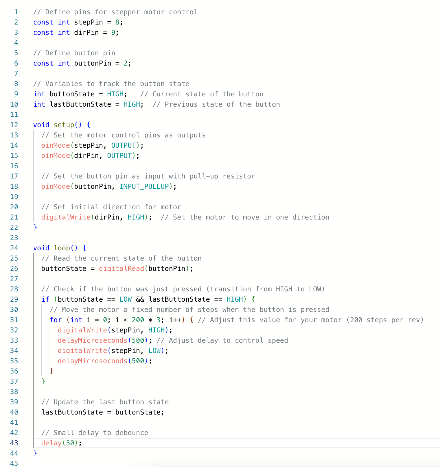
It's still acting a little funny, but I think this is a good spot to transfer to physical items to check out the situation clearer. It's almost perfect, but I still need each button press to turn the stepper motor the same number of rotations.
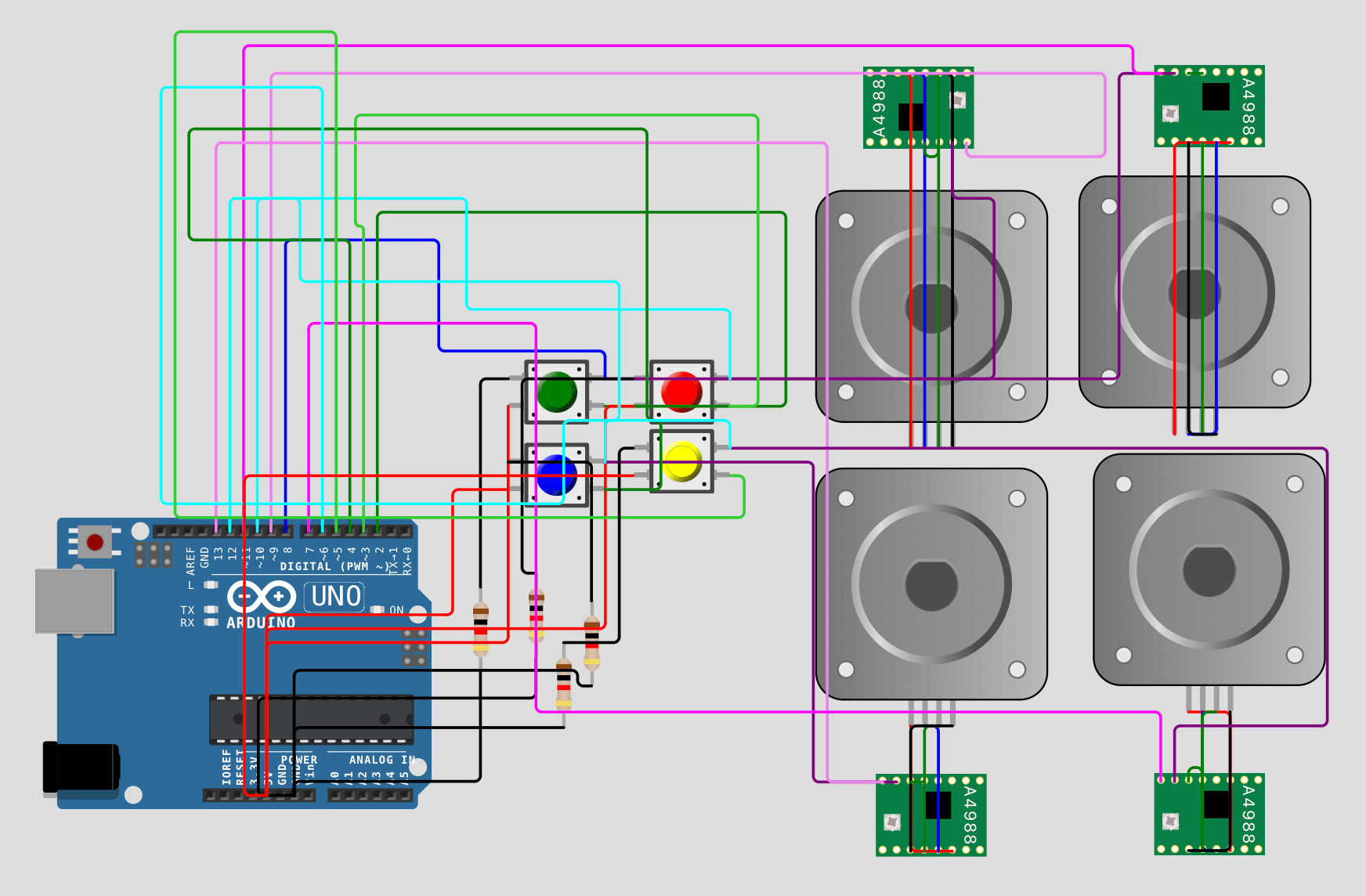
This is what it looks like with four buttons and four stepper motors:
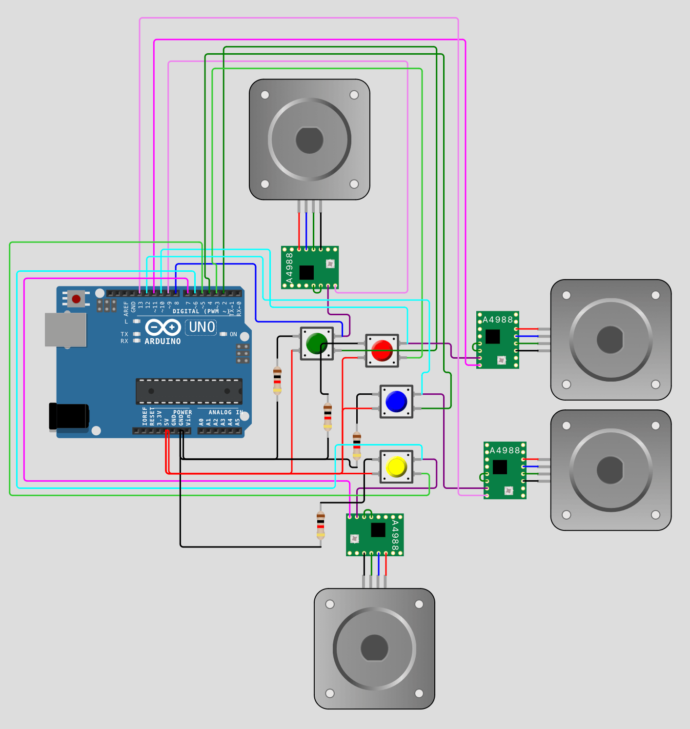
I tried to have the wires overlap as least as possible, but this is how it will look like with a more realistic setup (the buttons together and motors together):
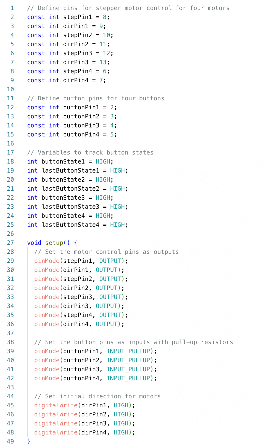
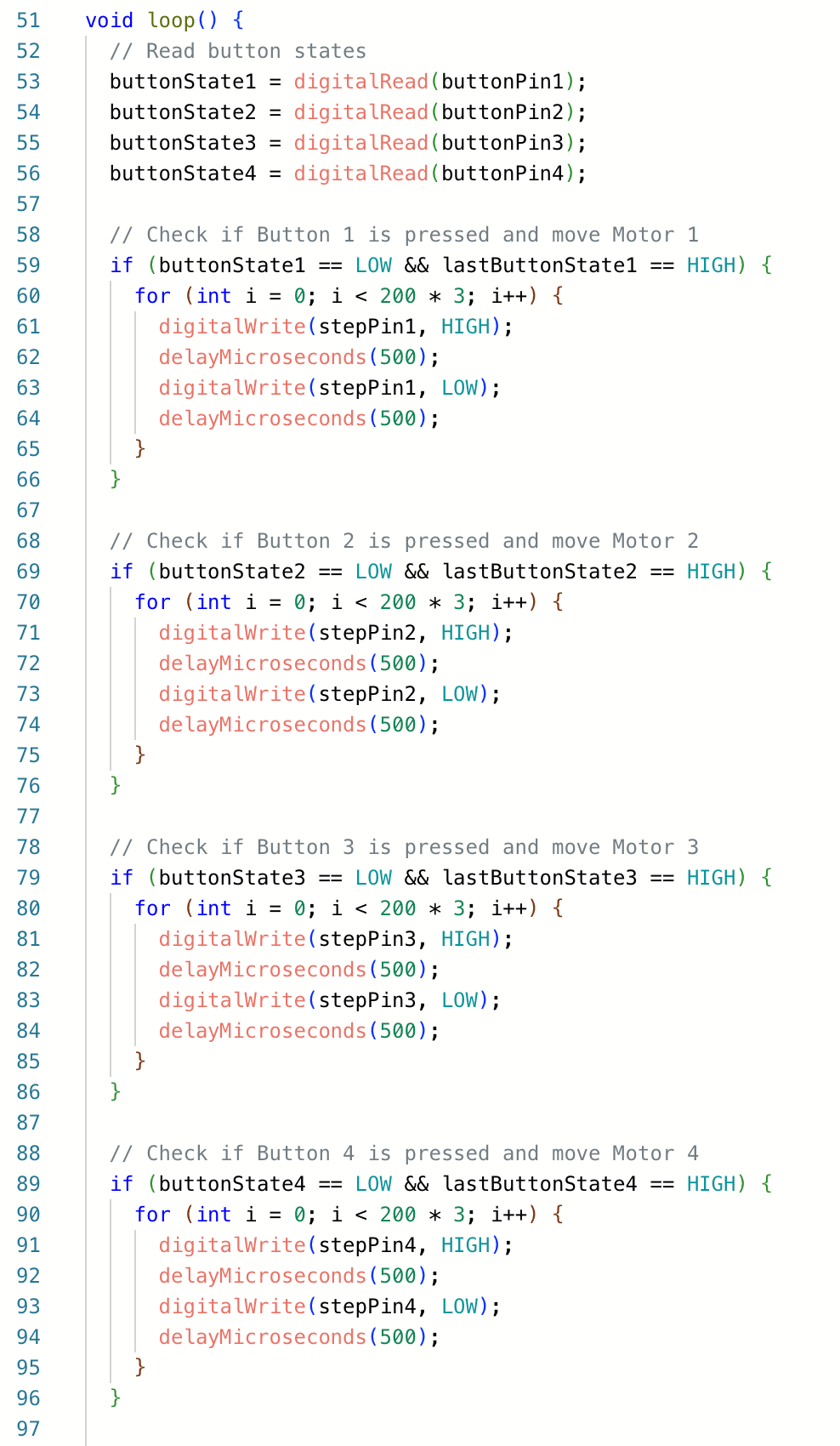
This is the code expanded to 4 buttons:

And this is a video of the simulation being run: