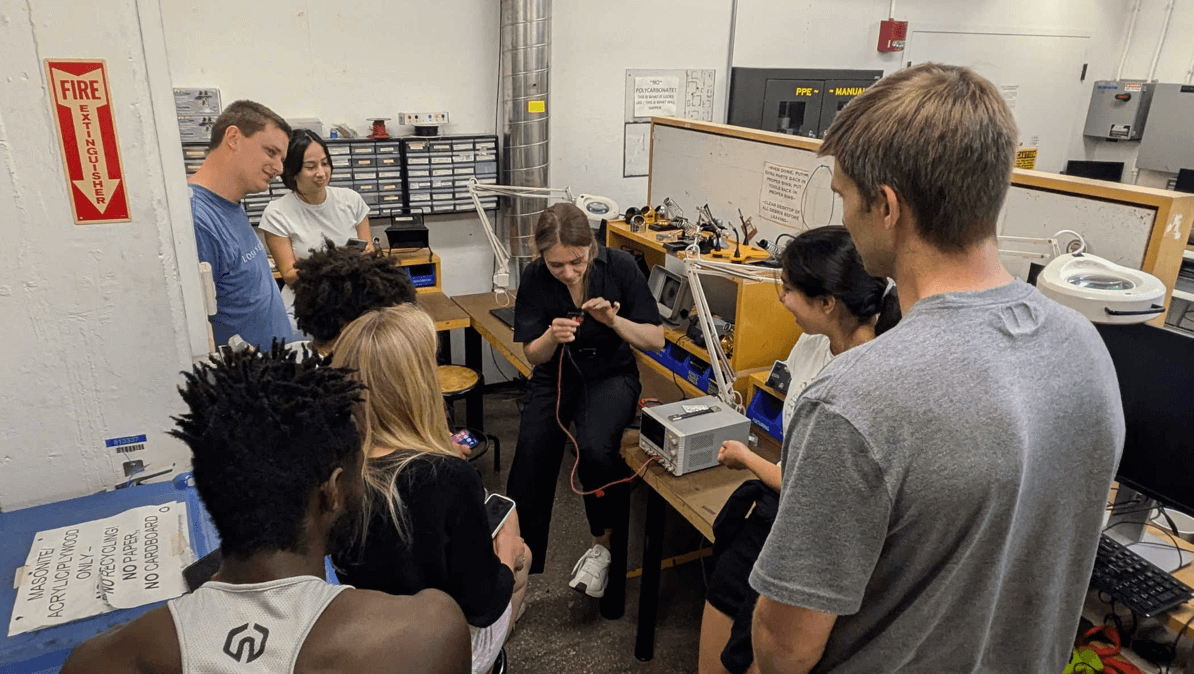
It's time to design my PCB! I am both excited and nervous because this is completely new to me. To start, I started thinking about which components of my circuit go on the PCB directly, and which i should just connect via normal wires.
As a reminder, I have four buttons, each controlling a different stepper motor. I figured that the buttons, stepper drivers, resistors, capacitors, and connectors (screw terminals or headers) for wiring the motors should go on the PCB. The buttons can be mounted on the PCB for a clean user interface, and the stepper drivers should be on the PCB to provide stable control signals and power to the motors. The stepper motors themselves, power supply, and any sensors should not be mounted on the PCB; they should be connected via wires using screw terminals. This is because stepper motors are large, require flexible mounting, and draw significant current, which makes them better suited to being connected off-board. The power supply will likely also be external and connected through terminals.
I have also decided to use KiCad, honestly mostly because Diana used it, and she described it in a way that appealed to me. Putting everything together was overwhelming in the beginning. I didn’t know where to put all my components relative to each other, so I decided to start with the buttons, the visible part of my circuit. I decided to have them be placed above each other in a vertical line.
This is my current layout:
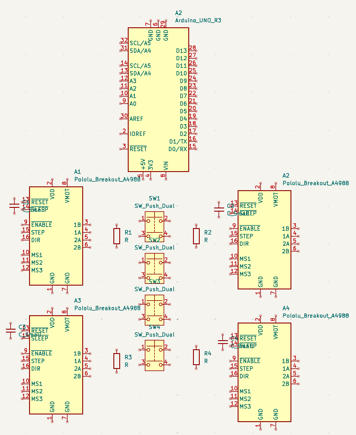
When connecting the points, I found it much cleaner and easier to use labels, but in hindsight, that masked the difficulty I would later have when I transfered it to PCB design mode.
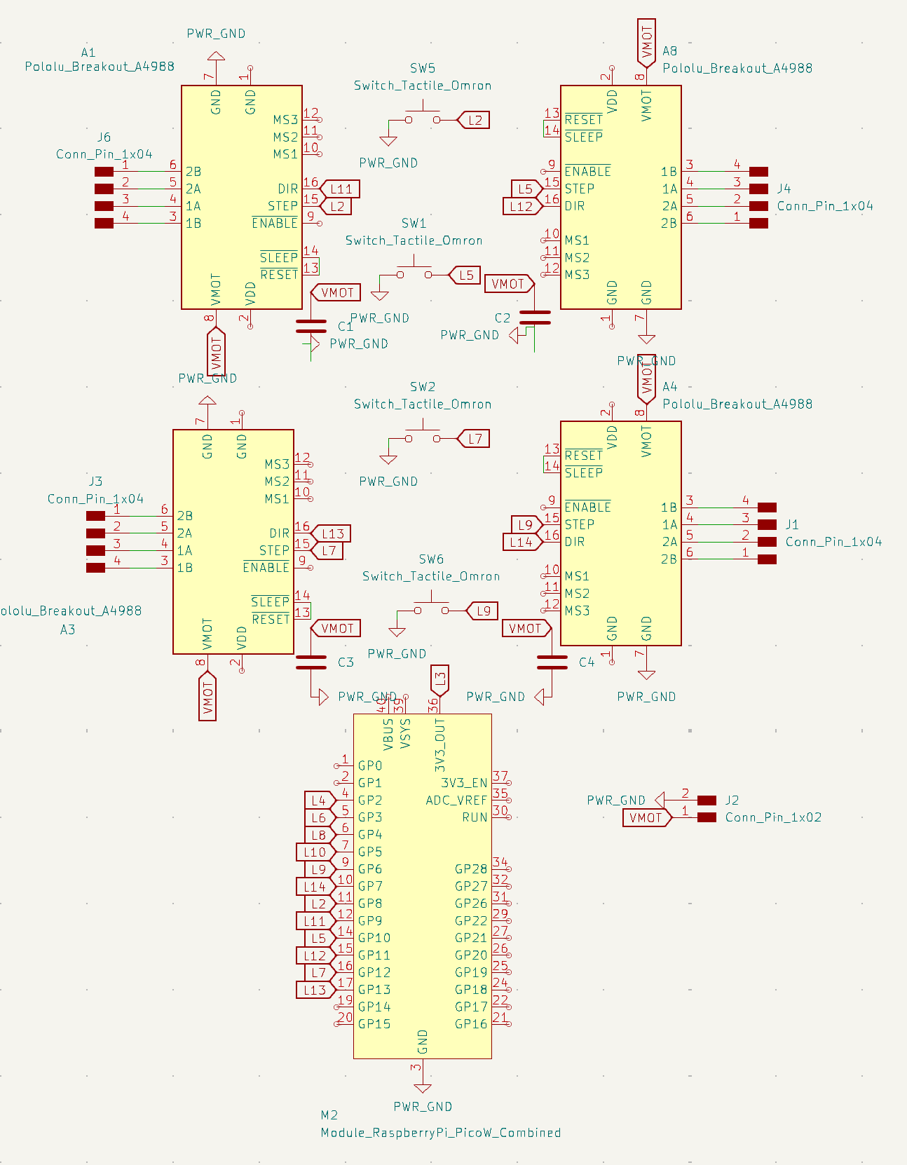
After this, I transferred everything to the PCB editor on KiCad, and started drawing the traces. This was the most tedious step. I had to repeat it many times because there would always be that one trace that could not make it to its destination. I tried multiple configurations and layouts, all to no avail. I considered adding a second layer to my PCB, but Anthony advised me against that, saying it would be much more complicated. He taught me how to instead have a resistor "jump" over a trace. He also recommended that I change what pins on my microprocessor my components were connected to in such a way that they would be less tangled up together. Here are some of my attempts:
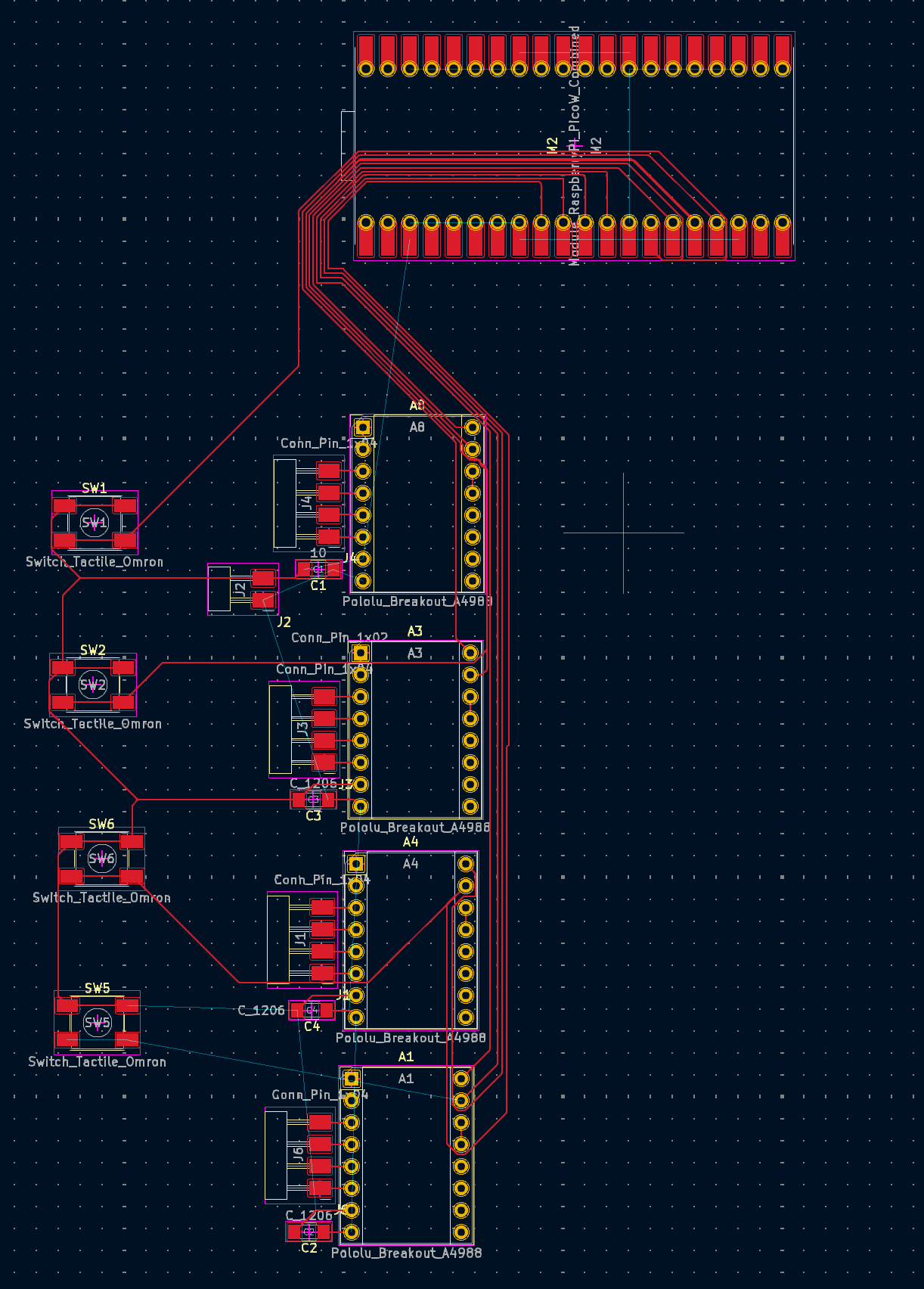
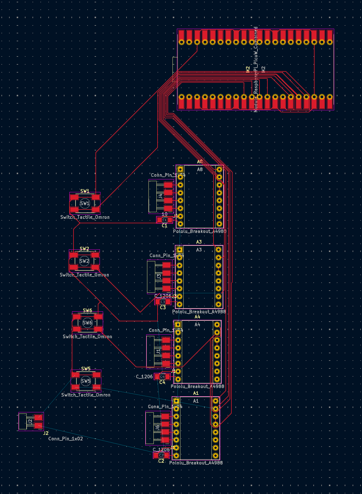
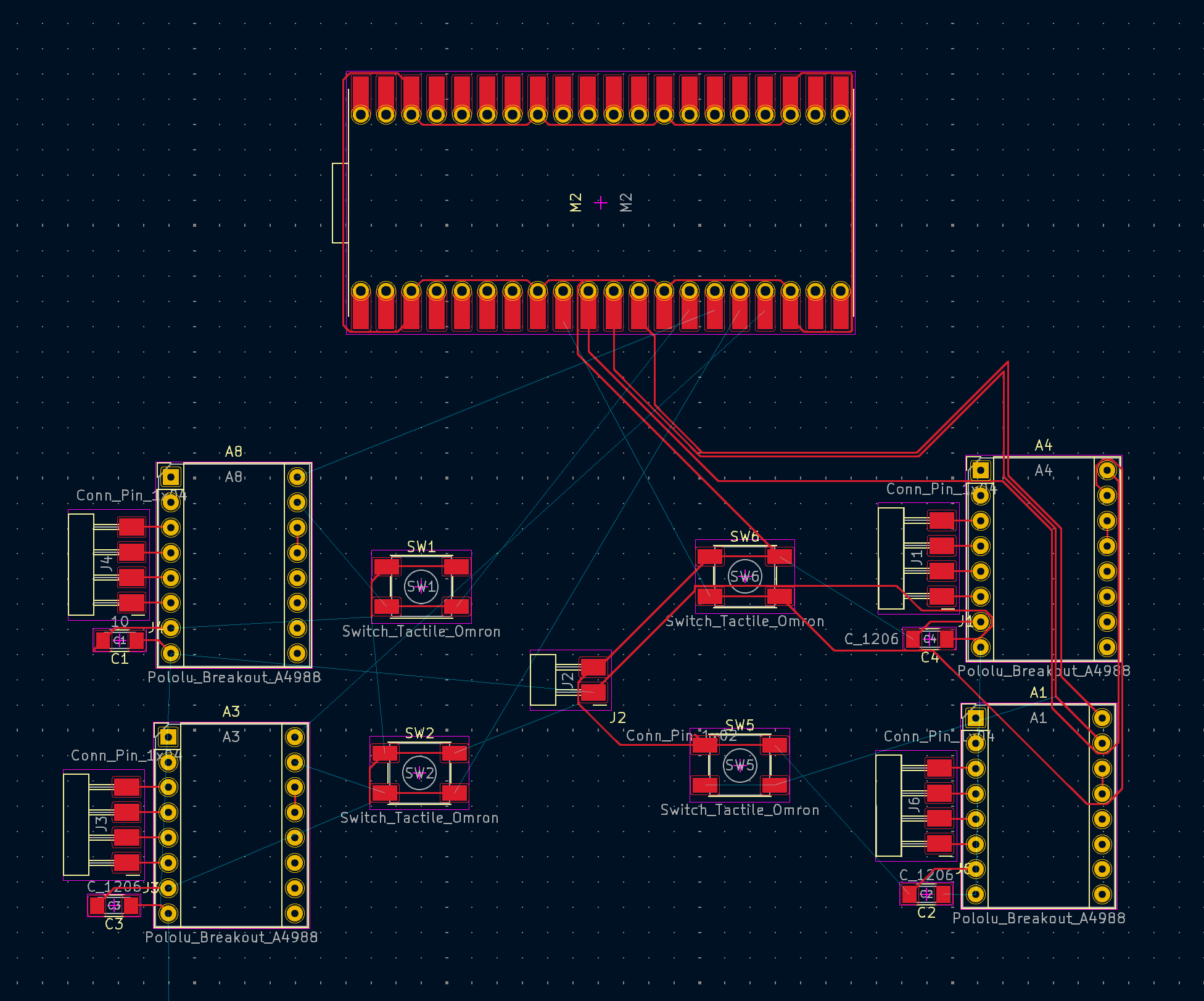
At this point, especially after seeing my teammates' reactions to how big the PCB I was planning to make was, I started getting concerned about starting off with such a complicated design with so many components. What if during soldering, I ruined my board and had to restart several times? I shared this concern with Anthony, who agreed that it may be better to leave this design for later, for my final project, while I familiarized myself with everything a little bit more with a simpler board first.
So, I pivoted this week's project to a PCB that will help me during Input Devices week. For my vending machine (final project), it would be nice to have a way of telling whether or not a coin has been inserted. This can be done by shining a light at a particular sensor and checking when the light stream is interrupted. To do this, I need a phototransistor. Here is the KiCad schematic of the new PCB:
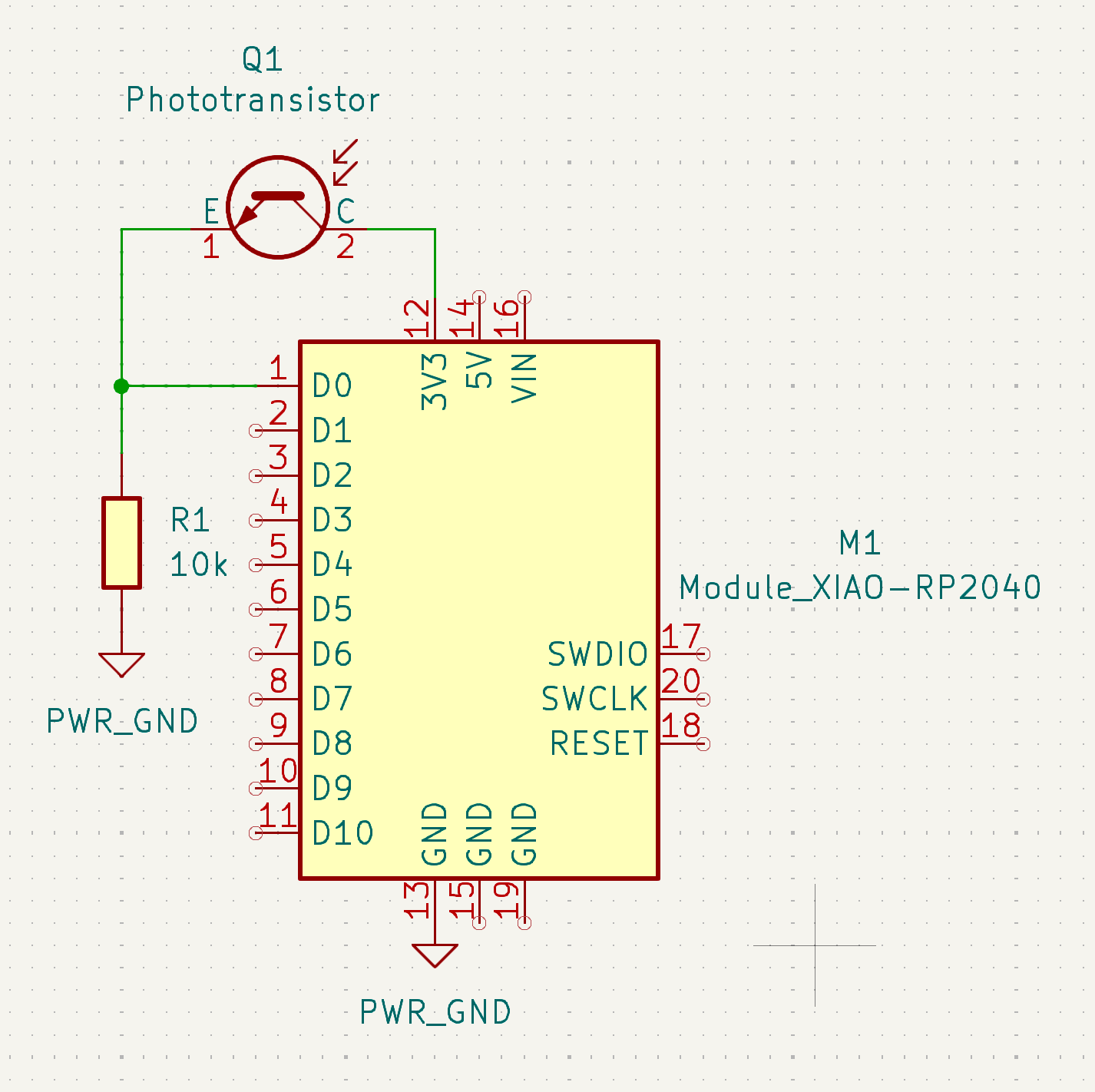
It features a phototransistor, a resistor, and a Xiao RP2040 microprocessor. Routing this in the PCB editor was much, much easier this time.
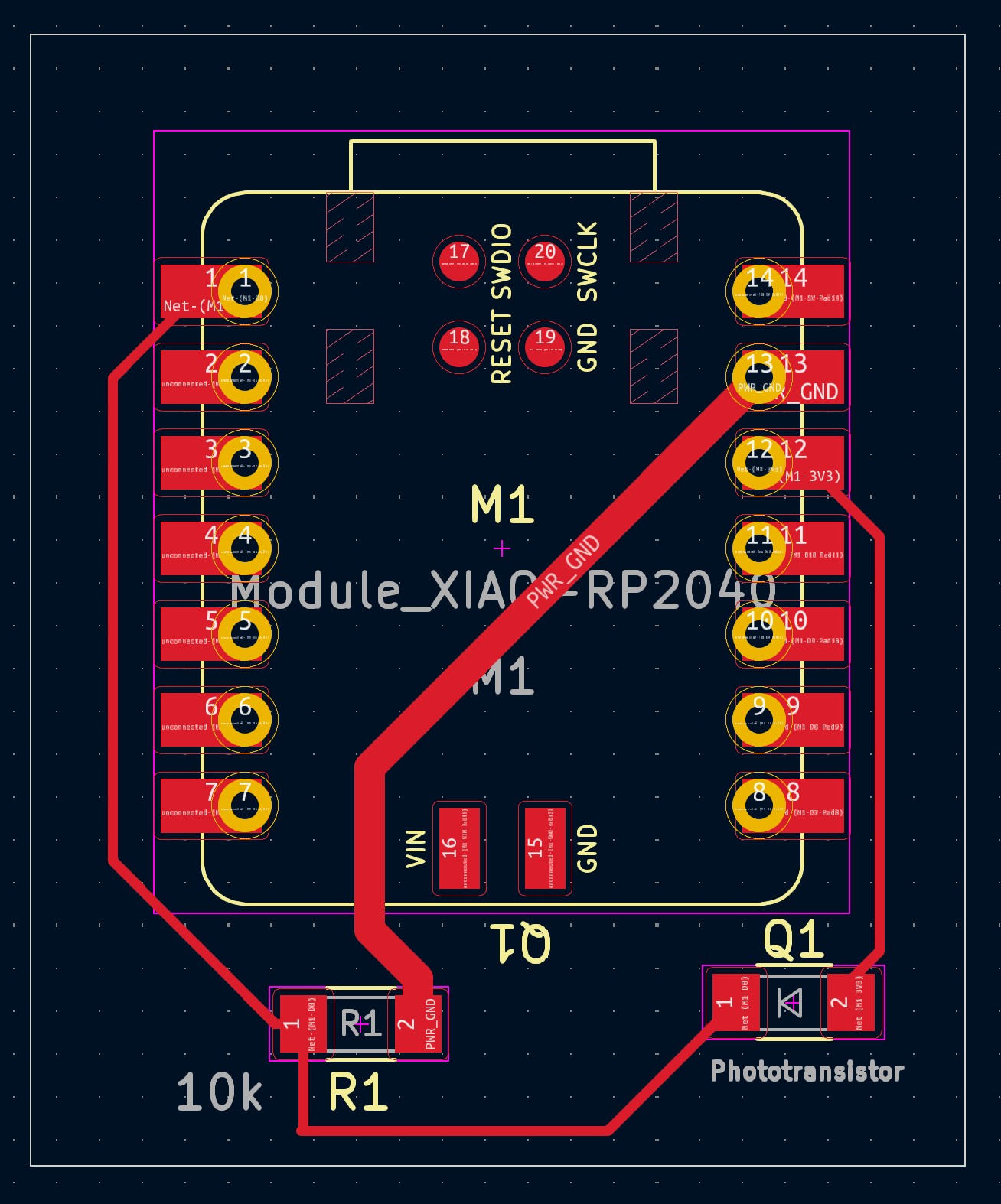
The traces carrying potentially large currents have to be thicker than the ones just sending signal. Therefore, I have two trace thicknesses: 0.9mm for the GND traces, and 0.3mm for the rest (I don't have a power cable here but it would have also been 0.9mm thick).
I'm excited to mill this PCB!
We started with a simple water wheel analogy: current was the amount of water, voltage was the height it falls from, and resistance was the wheel itself. Gradually, we got comfortable with the multimeter, measuring resistance, voltage, and current, and testing closed circuits. We then set up an ATTiny microcontroller with a rotor to observe in real-time. Diana showed us how to use the oscilloscope, like capturing a signal snapshot and adjusting the axes to see changes better. She even had us feel a resistor heating up from the power supply to show the effect of voltage—keeping it under 20V so it was safe. By the end, we’d worked with the multimeter, oscilloscope, and power supply, gaining some practical experience with microcontroller circuits.
