CAD / Parametric Design
Learnings:
Raster - think of images as pixels on grid
Vector - svgs, can send to laser cutter as lines/arcs, not dots
Parametric Design - set parameters, then define measurements using those variables. Allows for easy changing later.
Tools: (in FreeCAD)
Snaps: puts shapes into point in grid
Container (hierarchy) of related parts, can adjust their relation to each other.
Extrude: lift up 2D to 3D / Revolution
Loft: vary the different depths of shapes, create surface between them.
Sweep: sweep shape along line: circle to create faucet
Symmetry Operators: mirroring, create diff planes
Pads/Pockets: create shape, “drills through” like hole punch
Fillet - smooth out, 3d PRINTING can’t do corners
Offset - tolerances to fit together need to account for laser beam accuracy.
Cloning: maintains connections.
Constraints: draw lines that must be upheld via constraints
Projection: face onto 2D tool + Slicing!
Assemblies: constraints between two diff parts (make something coaxial)
Assignment: Model a possible final project.
I started out in FreeCAD, as that is the software demo’ed by Neil.
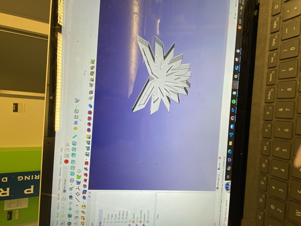
I want my possible final project to be a pair of wings that automatically move autonomously.
Unfortunately, while making this website, I compiled the website’s contents into the folder with my FreeCAD files, so I lost all my CAD. All I have is this one photo I took:
My process consisted of drawing the sketches and then extruding them. I used FreeCad’s symmetry operators (mirroring) to make sure the wings remained symmetrical.
Upon extruding, I drew onto the top face and cut into the extrusion to create the layered effect.
For parametric design, my variable was the length of the top arm. All other arms of the wing structure were fractions of the top.
Other work:
Designing website, writing application to enter HTMAA
Files:
As mentioned, due to the unfortunate loss of my FreeCAD files, I don’t have any files this week D:
