Week 5: Electronics Design
# Assignment
This week’s assignment was to use an EDA tool to design a development board to interact and communicate with an embedded microcontroller.
# Picking a microcontroller
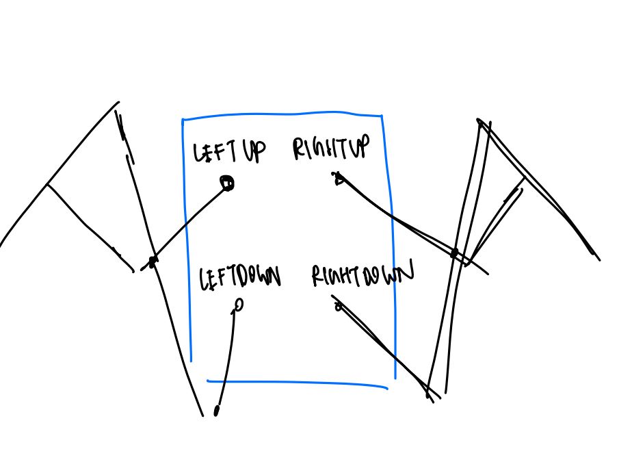
I wanted to design my board so that it could work with my final project, which would be a pair of motorized wings, with movement controlled by a joystick.
Given my initial sketch, I wanted to have 4 Sirvo motors and a joystick as peripherals for my board, so my microcontroller of choice needs to be able to have enough digital input/output pins.
I also wanted my board to be relatively small, since I want my wings to be wearable.
After some research, I was stuck in between the Xiao RP 2040 and the ATmega328P.
Both have PWM capabilities, which is essential for controlling my Sirvo motors. The ATmega328P was the microcontroller I looked into last week and was more familiar with. It is well documented and has many pins.
However, I chose to design with the RP 2040 in mind due to its built-in USB connection, small size, and pre-made schematic in the fab library.
# Designing Dev Board
Each Sirvo motor needs a PWM signal, 5V, and GND. The joystick needs 5V, GND, Horizontal Input, and Vertical Input.
I want a left upper, right upper, left lower, and right lower motor, so I used the 2x3 pinheads for the Sirvo motors, separated by upper and lower.
I used a 1x5 pinhead for the joystick. I also added an LED + Current limiting resistor, which I thought would help in terms of debugging.
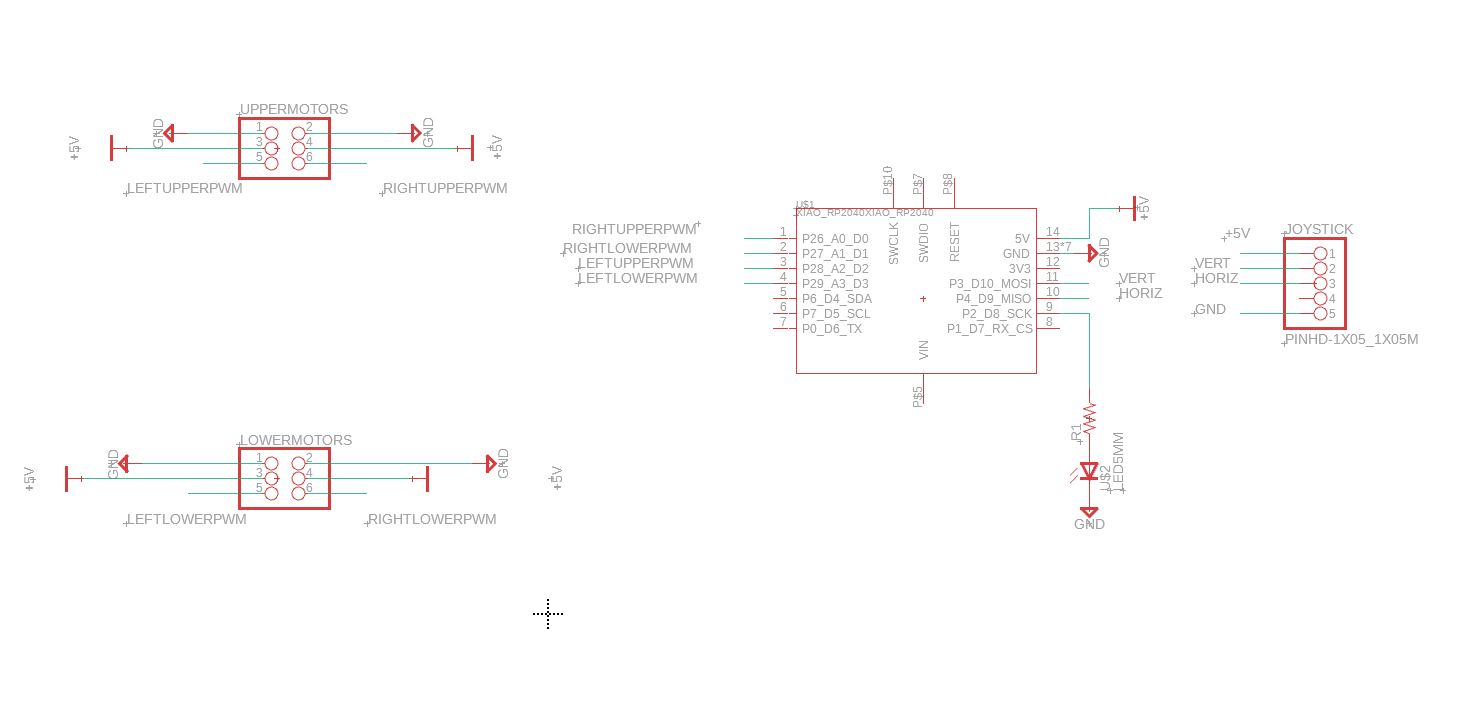
Initial Schematic
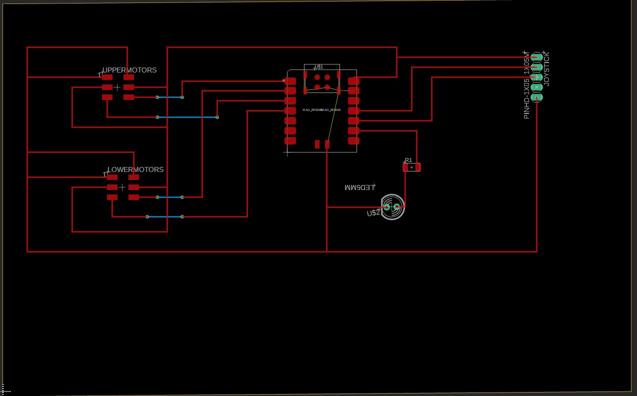
# Wiring Up
Wiring was … messy. Given that most of the digital outputs for the Xiao are all on one side, it was hard to wire my 2x3 pinheads without intersection.
Additionally, with all my peripherals needing ground and power, there was even more mess. Using the two layers of the board (using the routing tool, hitting the space bar to create a hole), I was able to get around intersections but I’m not happy with having to do that since it requires a double sided board.
Because my project seems to be very power intensive, I will probably also need an external power source outside of just the Xiao for powering the Sirvo.
# I fell ill at this point so stopped here, but came back to this board next week.
# Redesigning:
Anthony pointed out a couple issues that needed fixing:
- Use surface mount parts rather than through-hole parts. Since my board is single-layer, soldering a through-hole part would be difficult.
- Use external power supply for motors. This required creating four extra pinheads to connect to an external power supply.
- Xiao RP2040 digital high is 3.3V, not 5V.
- Pull-up/Pull-down resistors for switches are so common that they’re implemented in the microcontroller. We just need to set a pin as pull-up/pull-down rather than incorporate resistor in our design.
- Since we’re doing a single layer board, cannot use vias.
I also decided to use two switches for controlling the Sirvos rather than a joystick since buttons were easily accessible in lab.
What really helped was rotating pieces around to reduce the # of intersections, and using a polygon fill connected to GND for easy access to ground.
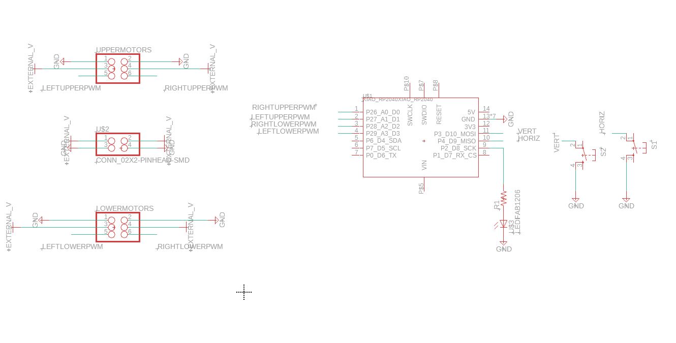
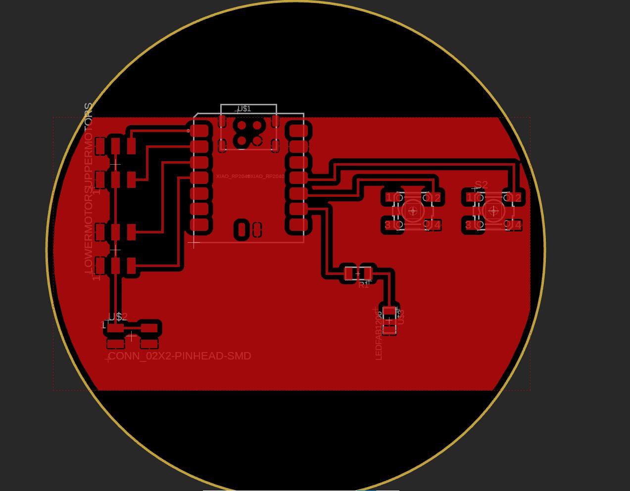
Updated schematics
# Learnings:
Things are in parallel if they share the same ground. We don’t need to link 5V port directly to the power source.
One helpful tip is to make an entire layer ground/power, and another layer the I/O ports for easy wiring. Will need to ask Anthony for more info because I don’t completely understand this.