Week 6: Electronics Production
Assignment
Make and test a microcontroller development board that you designed.
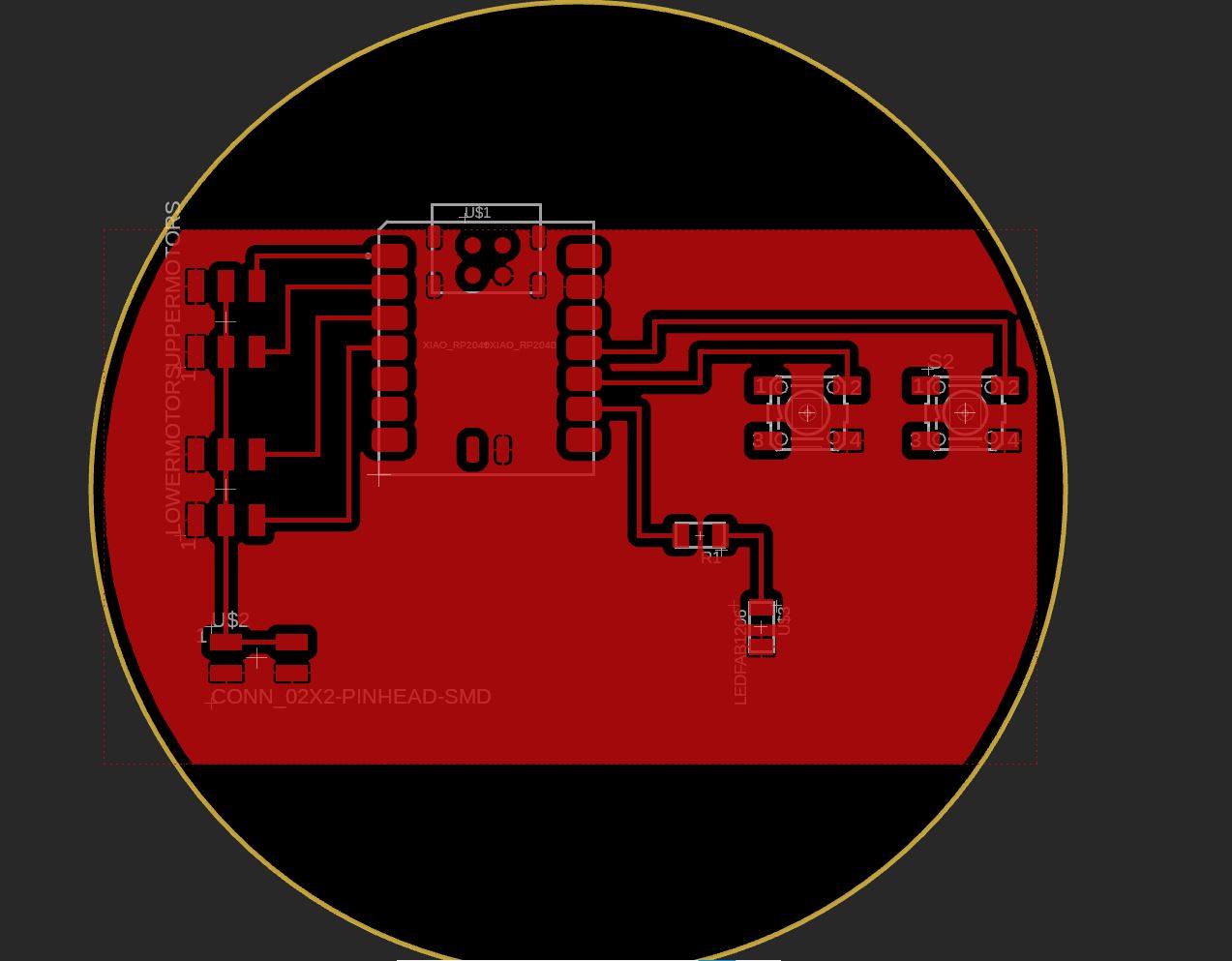
Redesigning board from previous week
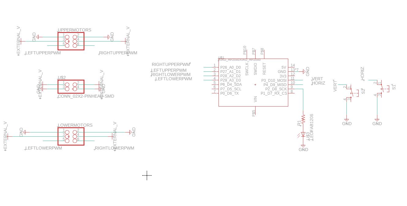
Last week, I designed a board that would use the Xiao RP2040 to control 4 Sirvo motors using buttons.
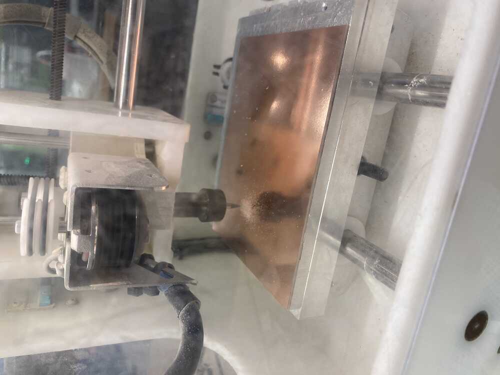
Milling
I wasn’t able to make group trainings for the milling machine so I was behind, but Anthony, Alex, and Sam helped me work through it.
Steps:
- Export PCB as GBR zip file.
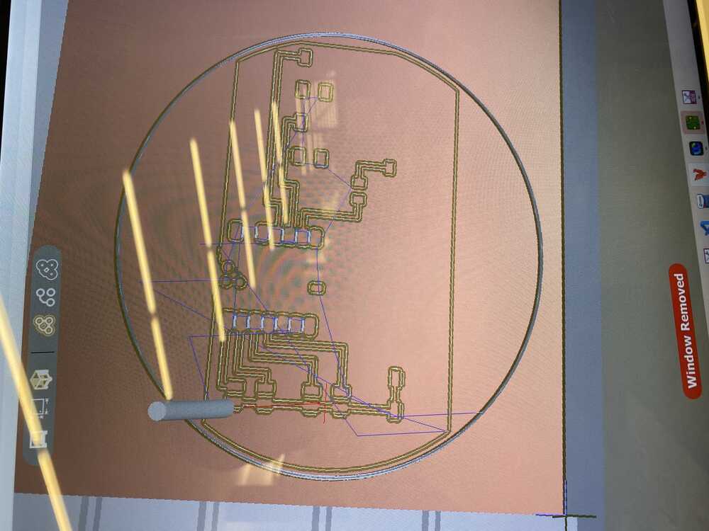
- Import into milling software with copper_top as top, and outline as profile.
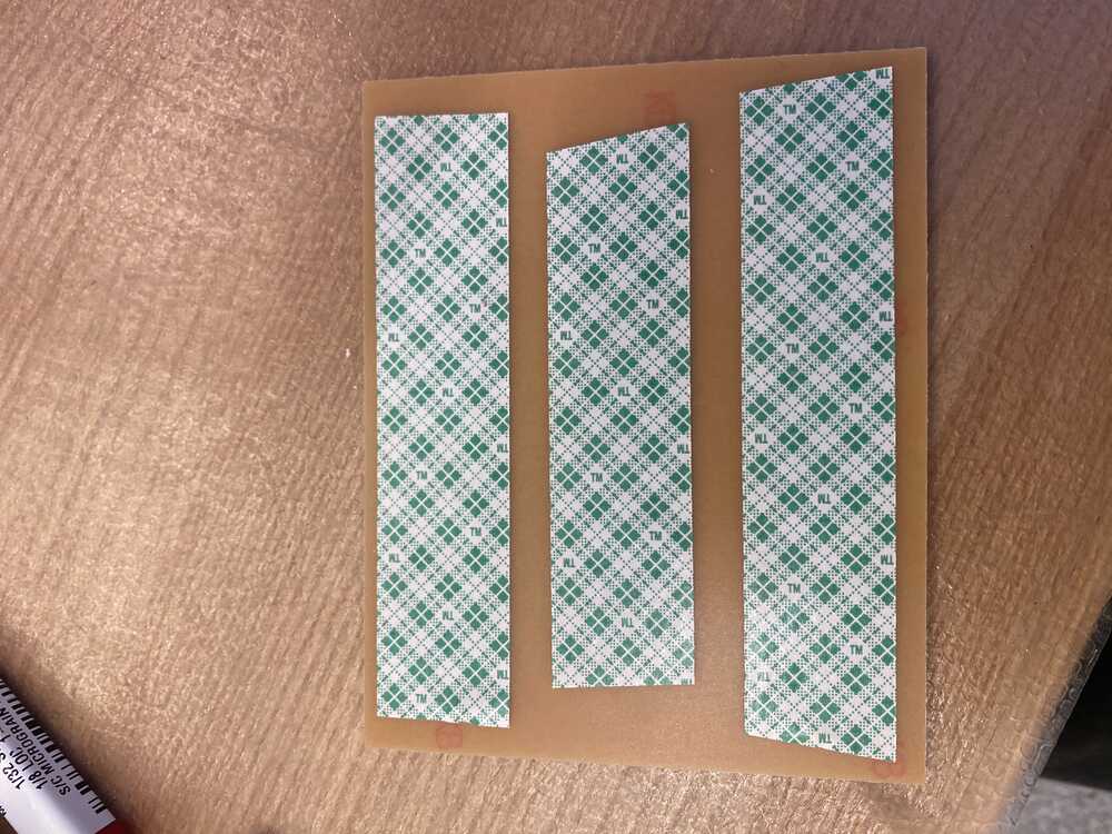
- Using double sided tape, secure the copper onto the milling platform.
- Adjust where the mill’s origin is, along with the outline’s placement on the board.
- Specify which tools to use: 1/32 PCB conservative, 1/64 flat end mill.
- Clicking start prompts you to change the tools. Put wrench on top, wrench on bottom. Turn clockwise to loosen. Be careful not to let the mill hit the base.
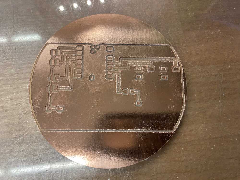
Fresh from mill:
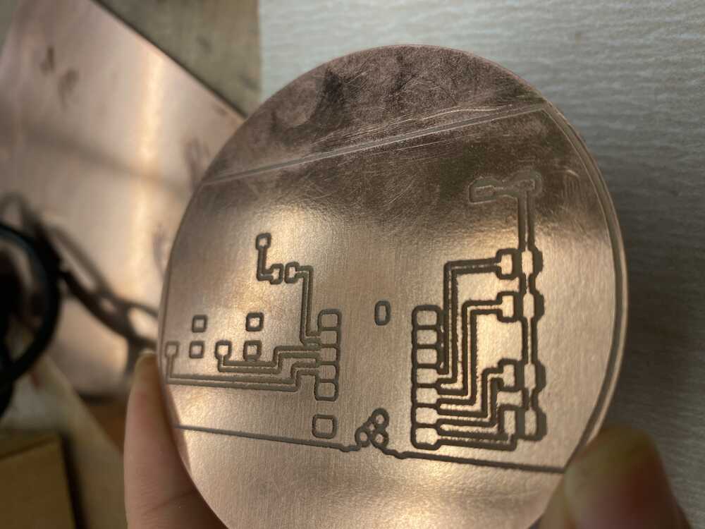
After using sandpaper to clean it up - much better!
Soldering + Testing:
Aah..soldering. My first time soldering was during the EECS FPOP, where they brought us to the lab and had us practice soldering. I sucked then.
My next runthrough with soldering was in 6.115, where we were allocated 30 minutes for a soldering training and I ended up taking 1.5 hours - only finishing thanks to a TA who took pity on me.
I have shaky hands!! So I was unconsciously trying to avoid this part of the assignment… and ended up putting it off for two weeks.
After practicing a ton on resistors, I decided to go for it. The issue is - the pieces for this PCB are much smaller than I was used to, which required a much more delicate hand.
On my first pass, I ended up yanking the trace off the board.
Alec helped me a lot through soldering the board - some tips he gave me were to hold down the edges with the solder for stability. For more difficult components, he showed me how to use the solder paste and hot air gun.
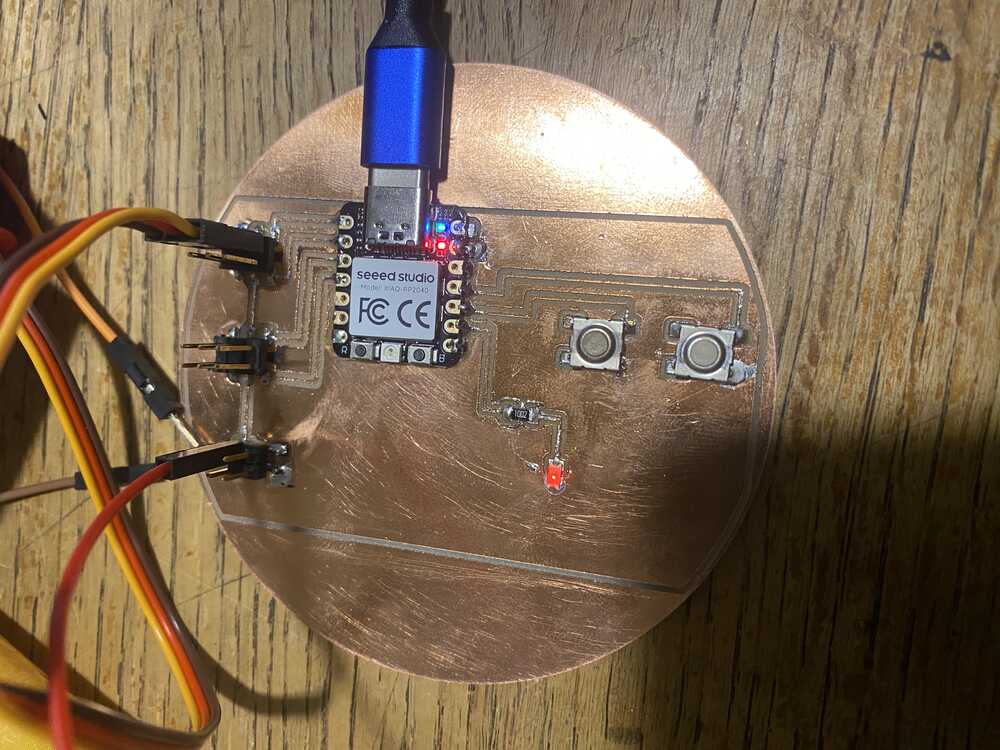
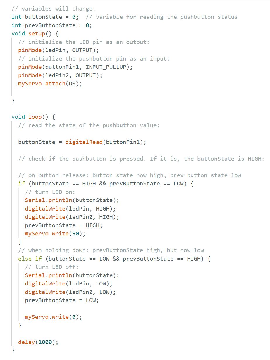
In the end, my finished board worked - I was able to control a motor with the button! Programming the Xiao RP2040 was easy thanks to the USB connection, which allowed me to upload code into the Xiao using the Arduino IDE.
The only issue was that my USB-C cord was only transmitting power, not data, so I had to use another one. ’
Getting my board to do what I wanted to do was more difficult. Sam helped me debug a lot of my issues, which was caused by my poor soldering not actually connecting traces.
The multimeter proved super handy! To check if traces were connected, switch the multimeter onto resistor mode and look for the ‘Wifi’ looking symbol. When there is a connection, there should be a beep.
When checking for voltage, place the black end on ground and the red end on what we want to measure. Switch the voltmeter to the voltage value that is greater than the voltage we are measuring.
Finished board! LED lights up :D
Notes:
When powered by the USB-C, GND pin of Xiao is an output of the USB-C’s ground.
The Arduino library, with the XIAO RP2040 package, acts an abstraction over the underlying microcontroller. pinMode sets a pin as input, output, input_pullup, etc.
Serial.println() is super helpful for debugging.
