# Week 3: Embedded Programming - Bird Pinball
This week’s assignment was to write a program for a microcontroller and simulate its operation.
I took 6.115, Microcontroller Laboratory last semester so I’m pretty comfortable with microcontrollers themselves.
However, I’ve never taken circuits so last semester was a lot of guessing and praying nothing blew up. This week was a lot of learning more about circuits and refreshing my microcontroller knowledge!
Assignment: Browse through datasheet for microcontroller, write a program for it and simulate its operation.
Slideshow with electronics basics
In this class, we won’t be using Arduinos. However, to get a good sense of embedded programming, I felt that Arduino had good documentation and the programming aspect was not too different, so I went with the Arduino Uno for simulation.
Simulation 1: Joystick/Motors
Pressing the left or right button controllers causes the corresponding Sirvo motor to move, like a pinball.
Pressing another button while a motor is moving interrupts that motor, allowing for fluid switching between motors.
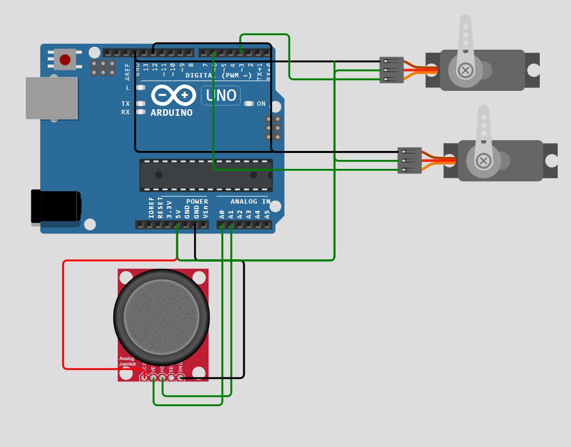
Analog Joystick:
VCC: 5V on Arduino
Vert: ANALOG PIN A0 (INPUT into Arduino)
Horz: ANALOG PIN A1 (INPUT into Arduino)
GND: Ground on Arduino
Joystick to Motor:
Analog Read: Maps input voltages between 0 and the operating voltage (5V or 3.3V) into integer values between 0 and 1023.
Write PWM out to servo (Pulse width modulation - motor position dependent on duty cycle)
Coding:
It was easy to get the Sirvo to move, but harder to get more complex behavior. Implemented interruption of motor movement by polling the joystick to see if a new signal was given. This raises an interrupt flag, which I process on the next loop cycle.
Project Link
Simulation 2: FT display displaying pinball movement.
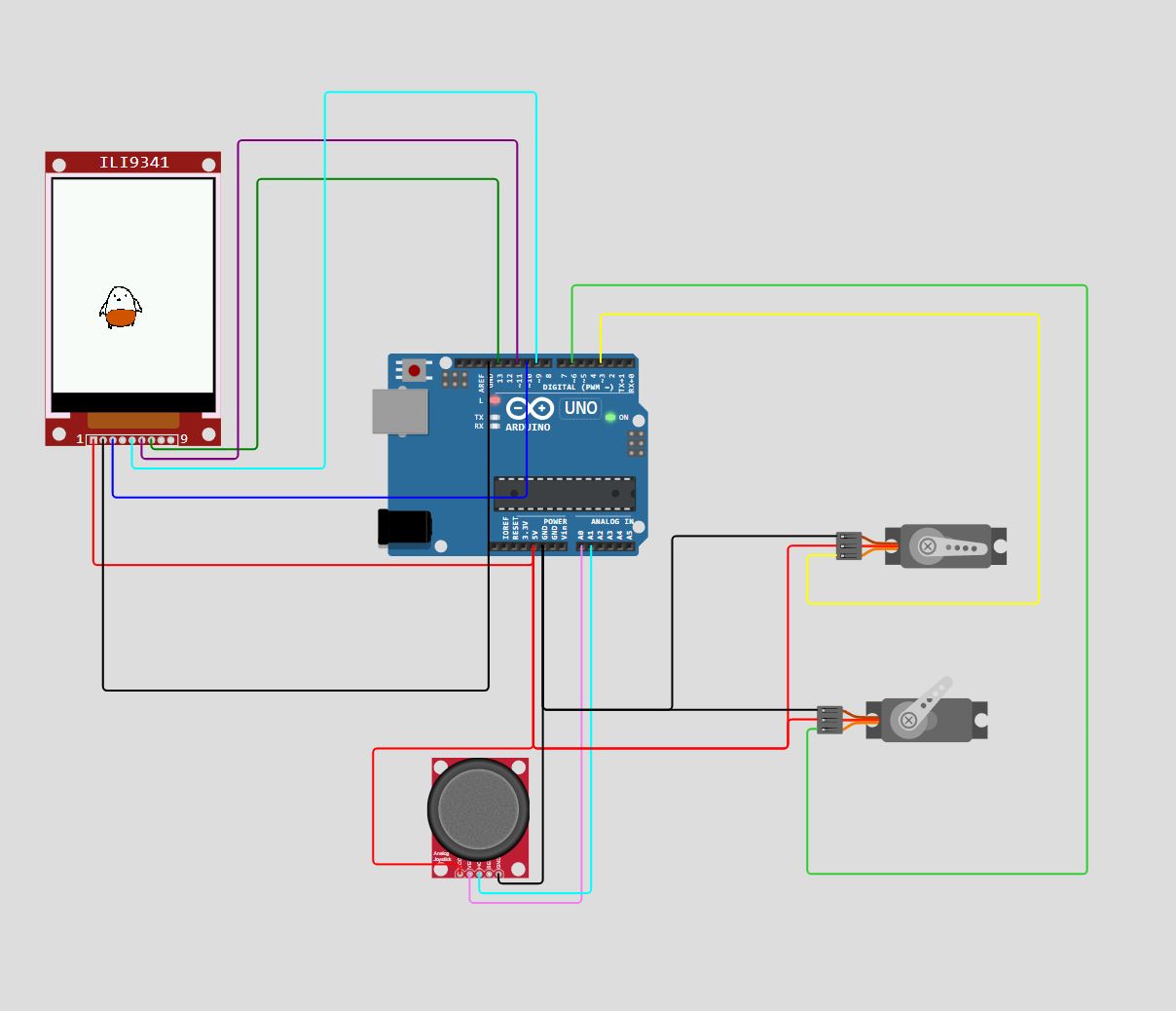
I plugged in the TFT display, and using the TFT Adafruit ILI9341 library to display images.
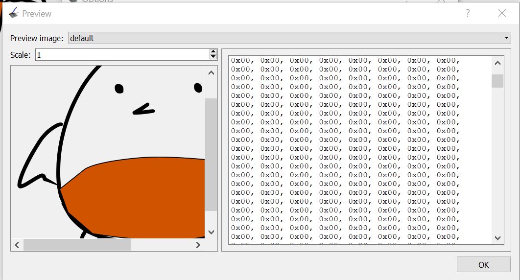
I drew my “pinball”, and downloaded lcd-image software that helped me turn my drawing into a 64x64 array of bytes.
Then, using drawRGBBitmap(), the TFT draws the array onto the screen.
I had some difficulty getting the pinball to smoothly simulate motion, since erasing and drawing the pinball took a lot of time.
Browse through datasheet / Learn electronics
Voltage: difference in electric potential (work potential)
Current: rate of flow of electrons (flow)
Resistance: difficulty for electrons to move through circuit (friction /electron resistance)
In series
Current is constant. The rate of flow remains the same, just like how water does when it follows one path.
Voltage drops across each component (based on resistance)
Current of one component = current of entire series
In parallel
Current is divided. Voltage stays the same.
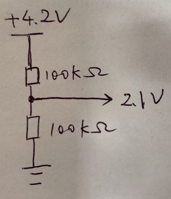
Voltage Divider (in series)
Drops of voltage in accordance to differing resistance values creates division of voltage.
Current = V (total) / R (total)
Current here is 4.2 V / (200k ohms) (same across series for both resistors).
Volage drop measured as V = I * R, so voltage drop across first resistor is current x R1.
Diodes: allows current to flow in one direction only.
Anode: positive side
Cathode: negative side
If voltage is applied across the diode, with anode more positive (in direction of cathode), current flows through it. If in reverse stage, no current flows.
Conducts electricity in only one direction, unlike resistor. If there is a voltage difference across a resistor, current will flow that way.
Current stays the same across components, so finding current across resistor = finding current across entire series. We want to make sure current across diode is limited, so limiting current on resistor = limiting current on diode
Voltage drops based on component’s resistance.
V total = V(diode) + V (resistor)
V resistor = V total - V diode
Current across resistor = (V total - V diode) / Resistor = (5 V - diode forward) / 5 Ohms.
Current won’t flow until voltage exceeds forward voltage drop. We can set appropriate resistance to figure out current across diode.
Capacitance: I = C * dv/dt (change in voltage over time).
Ability to store electric energy in field
“Filter” for changes in voltage
Because it stores energy, prevents drastic changes across switch. Instead, discharges!
Inductance: v(t) = L * di/dt
Voltage induced by inductor at this instance = L * di/dt (change in current over time)
Electrical circuit’s ability to store energy in magnetic field when current flows thru it
Energy: stored in electric field
Overall: Resistance: resist voltaqge. Cap: resists change in voltage. Inductance: resists change in current.
Buffering/bypass capacitors: 1 uF - 10 uF place at each digital components Stabilize voltage supply + reduce noise (caps reduce noise by quieting the fluctuations)
Current limiting resistors: put before diodes: 1K ohms
Pullup/pulldown resistors: 10K
Ensures digital input at pin has defined logical level even when no driver.
Pull up: connect input pin to high voltage ethroug resistor. If device switch pulls pin to ground, resistor limits current to safe level rather than being virtually no resistance.
Pull-down: connect input pin to ground. When no device driving, it is at 0. When at high voltage, resistor limits current flow once again.
Button debounce: capacitor, or use slow reads to prevent registering on and off multiple times.
Microcontrollers Datasheet:
In 6.115, we mostly worked with the ancient 8051, so I wanted to get familiar with a more modern microcontroller. I settled on the ATmega328P (datasheet), which is used for the Arduino, so I learned both! After wrangling assembly code for the 8051 all of last semester, coding in Arduino felt a little too… easy.
What is a microcontroller?
Integrated circuit with processor, memory, peripherals - allowing it to code and be a self-contained computing system.
Examples: 8051, Arduino
Within a microcontroller, there are different embedded architectures.
Von Neumann:
Single bus for instruction and data. Program code and data share same memory space.
Harvard architecture:
Separate buses/memory spaces for instructions and data. Parallel data and instruction fetches
Microcontroller Architectures: MCUs specifically for that microcontroller
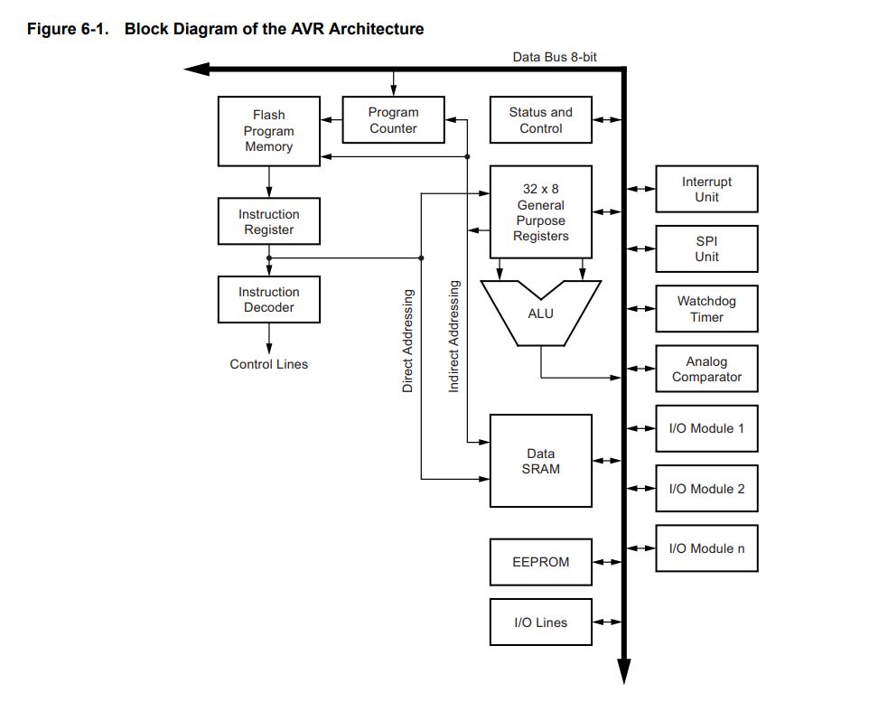
AVR: (Atmel- a modified harvard architecture)
Separate program/data memories, but single unified address space.
ATmega328P
Uses Harvard architecture - separate memories and buses for program and data.
32 8-bit general purpose registers connected to ALU (arithmetic-logic unit).
Workflow:
Code in C/C++ in Arduino IDE -> Compiles into binary hex file -> Flash binary into microcontroller’s program memory
Arduino Uno
Last year, I tried to implement a frequency detector using Fourier transforms on PSOC- when looking online, everything was documented for Arduino, so I was very jealous. Now I can take advantage of all that documentation!
Arduino Uno Datasheet ATmega328P micrcontroller, 14 digital input/output pins (reads either high 5V or low 0 V), 6 analog pins (read precisely from 0V to 5V) USB connections.
Programming Workflow:
-
Initialize: power supply:
V_in: supply external voltage supply directly to board - don’t need USB or power jack
Power jack: external power source, power adaptor.
USB connector: connects to computer, power/programming! -
Wire Up Digital/Analog Pins: Port 0 - 13: input or output digital pins.
A0 - A5: analog signals, from 0 V to 5V.
AREF: Analog Reference, used for ADC or as for external reference voltage for analog.
5V, 3.3V: can use to power others! Don’t want to draw too much current though.
GND pins: all connected to each other.
RESET: restarts program.
IOREF: provides operating voltage of microcontroller.
SCL: i2c communication to other devices in short distance: SCL is clock line, SDA is data line. Master sends message, slave sends back message.
MISO: slave to master communication
MOSI: master out slave in
SCK: clock signal for synchronizing.
CS: chip select: each slave device has unique SS/CS line, that when on, means swapping chip select.
