Week 8: Output Devices
# Assignment
Add an output device to a microcontroller board you’ve designed, and program it to do something
# Reduce, Reuse, Recycle?
In previous input devices week, I wired a Xiao RP2040 to read from an accelorometer! Although the acceleration was not very accurate, it was good at detecting the orientation of the board.
Additionally, in Electronics Production week, I wired an RP2040 to turn on/off a motor based on buttons.
Why not combine the both?
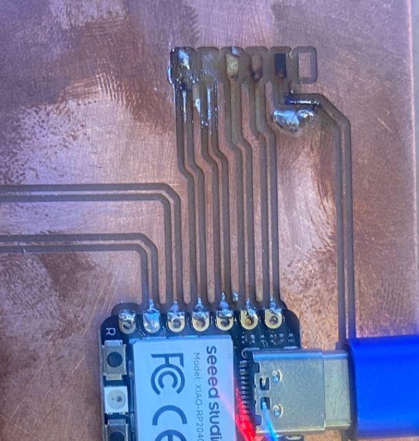
While trying to put in my Servo wires into the breakout pinheads, I ended up ripping the traces off the board.
Looking back, I could’ve soldered the Servo leads into the Xiao pins themselves, but I also didn’t think just controlling a Servo counted for output devices.
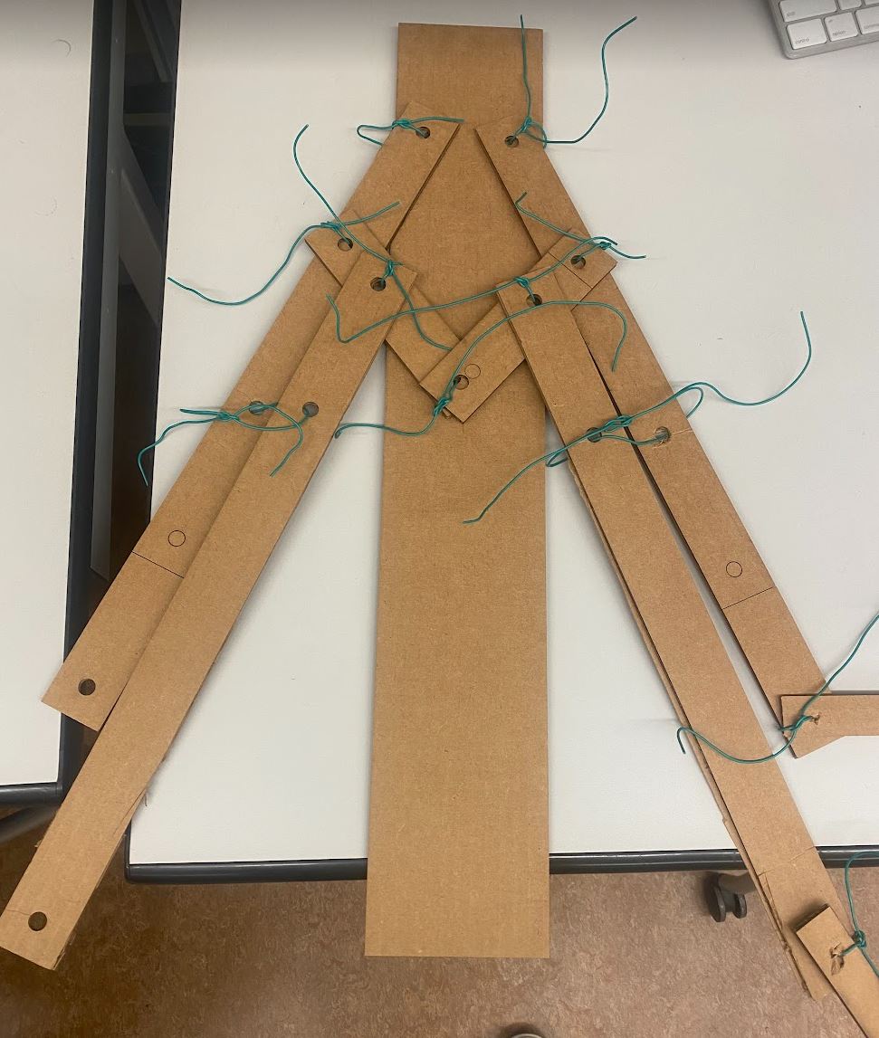
I decided to redo the board, and make something more aligned to my final project. I prototyped a design for my wings, which requires a motor pushing vertically to ‘flap’ the wings.
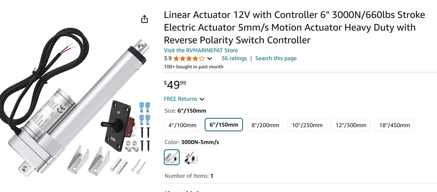
Looking online, thought about using a linear actuator, which provides that vertical linear motion for me.
These require high voltage and high current draw, so I needed a relay to control the actuator from the microcontroller. After consulting with Anthony, he suggested the stepper motor over the linear actuator for the following reasons:
- The actuator is overkill! $50 for 100+ pounds of weight, which is more than I need.
- Controlling the actuator requires an H-Bridge.
- The shop has stepper motors.
- With the DRV8248 chip, controlling the stepper is as simply as setting the direction and sending a PWM, where a step is taken on each rising edge.
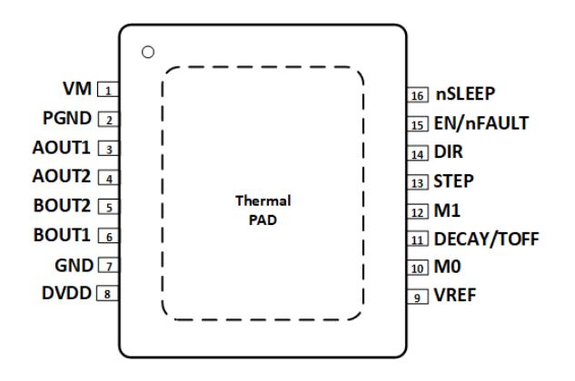
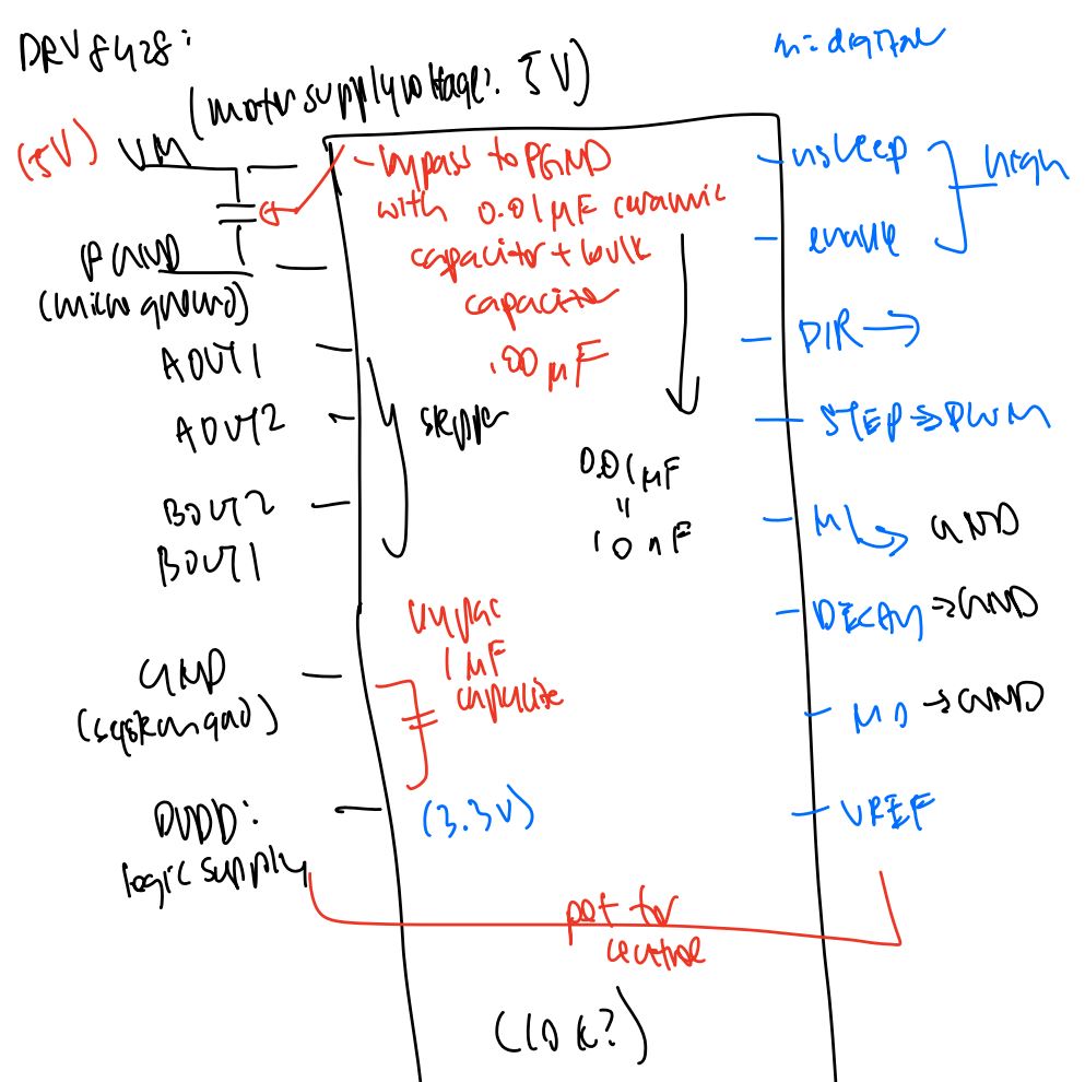
First, I went through the DRV8248 datasheet, drawing out what I’d set each pin to:
Designing
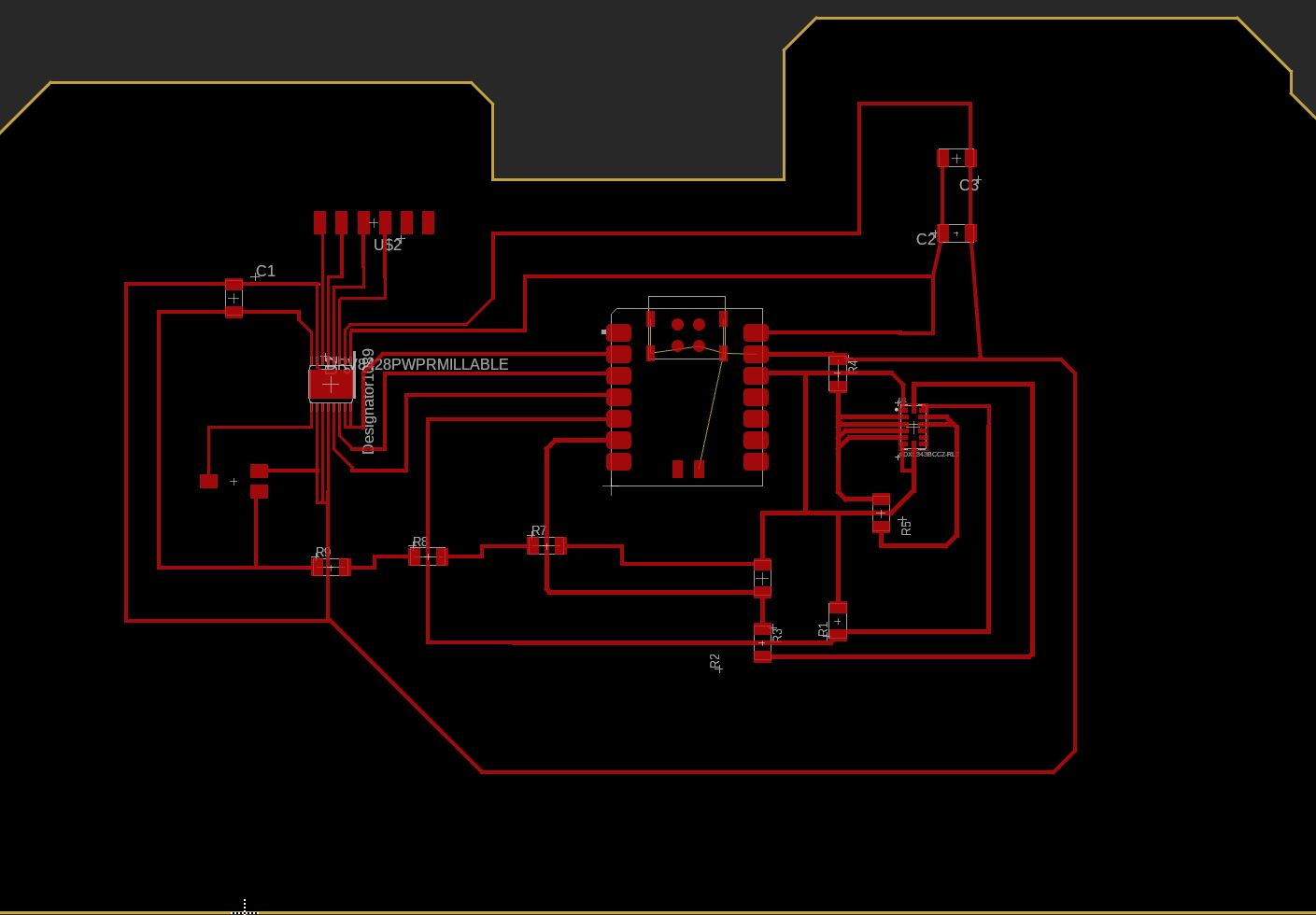
Time to take this to Fusion! I modified my accelorometer board from the previous week to include the stepper driver.
Some mishaps along the way:
- I was wiring bypass capacitors in series rather than in parallel.
- Pots are like sliding resistors. One end is connected to power, the other is connected to ground. The middle ‘fork’ is the output voltage.
Shoutout to the 3 0-resistors in a row there. I spent a couple hours trying to make this cleaner, but I fear this is the best I got xd.
The spacing between the DRV pins are absolutely tiny, so I had to modify traces near it to be 9 mil.
Milling/Soldering
It was getting late and I was rushing so I forgot to document most of my work.
There were a lot of soldering mishaps - almost all the pins from the DRV were shorted together because I used too much solder paste.
Additionally, when wiring a capacitor to the board, I ended up ripping the traces off.
Huge huge thanks to Alec for doing amazing CPR and saving my board.
To save the shorts on the DRV, he heated up a piece of copper and placed it on the shorted pins to wick off the excessive solder.
To replace the traces, he stripped a wire and soldered it over the ripped off trace.
I was gooped.. it was insane.
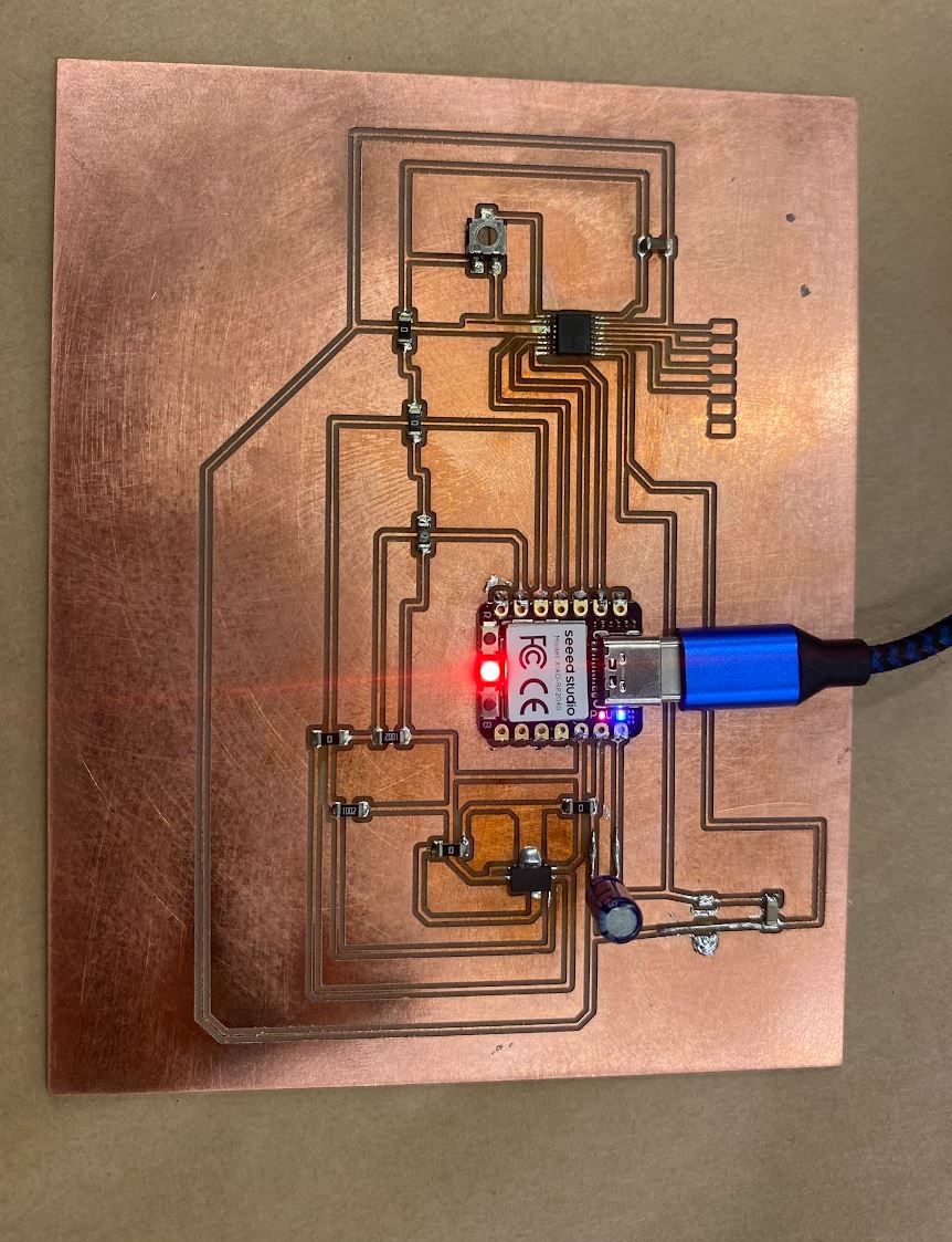
The board worked! I have to redo this board since the capacitor is very unstable, wired on top like that. Right after recording these videos, the cap got snagged on something and ripped the traces off D:
As seen, the motor moves in response to the accelerometer detections of orientation changes!
#Files
