Process ✏️
I used KiCad to design my development board. This week was a HUGE learning curve for me, and I know that I will continue to revisit this week
for weeks to come.
In short, here is a preview of my schematic and pinout. I used an RP2040 to measure heartrate sensor output from the MAX30102.
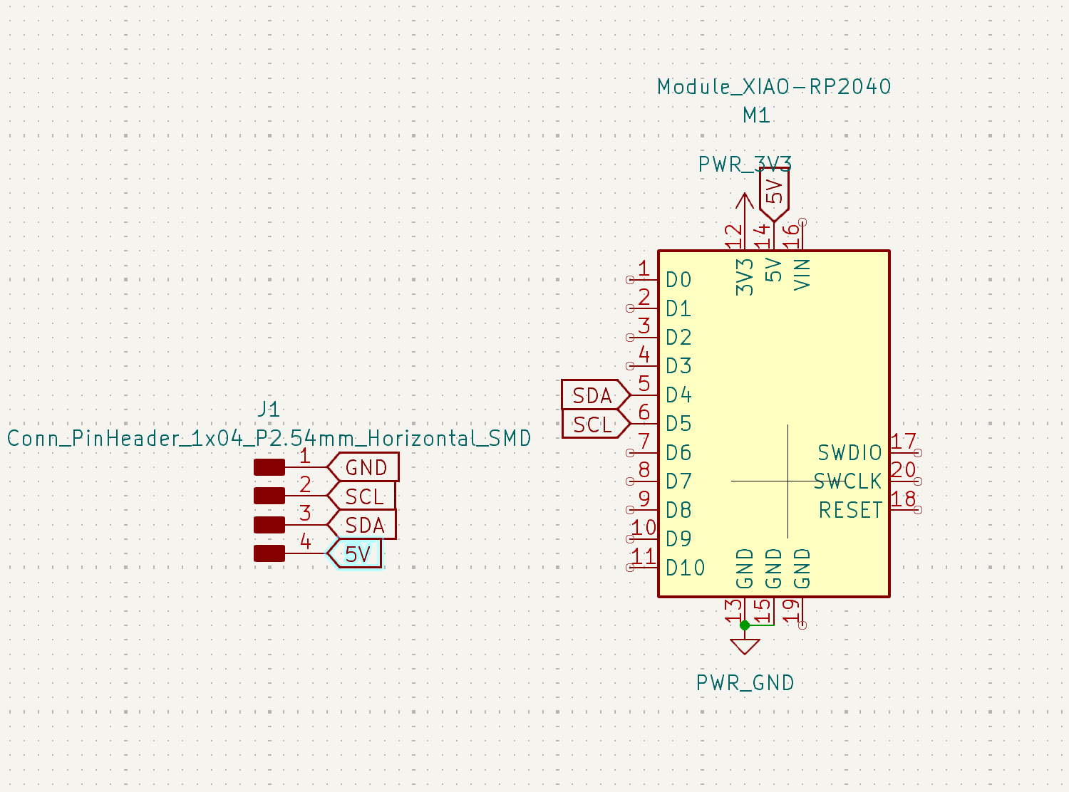 Using RP2040 to conect to i2C pins.

Ensuring that there is enough space between the microcontroller and pulsometer, and that the wires do the cross through the boards!
I kicked off this project by investing in some research. As I started to make design decisions on my schematic, I reached out to
our HTMAA teaching team.
To tie everything back to my final project, I want to create a "smart sports bra" that measures heartrate, body temperature, acceleration, and velocity.
Neil mentioned using the BNO085.
So, for a few key thinking: I'll be using the RP2040 as a microcontroller. For the group project, we used the ESP32 as a microcontroller
to blink a light. This was helpful to understand the microcontroller's capabilities.
Individual Assignment:
For my PCB (printable computing board) board, I want to be sure there is room for flexibility in the coming weeks as my final
project may shift. This is a super new area for me. I have so much to learn!
I reviewed our HTMAA syllabus resources in EDA (Electronic Design Automation), sketching, schematic entry, component placement,
(auto)routing, simulation, fabrication, layers, angles, vias, power planes, ground pours, design rules,
DRC (Design Rule check), ERC (Electrical Rule Check).
After doing so, I know I want to include the following ESP32 and BNO085. I will connect unused pins to headers. In the future when I narrow down sensor choices, I can make a small board with the
sensor and use some wire to connect it to my main board.
ESP32: Followed using a KiCad tutorial
I'm a bit stumpted because I am trying to import these schematic
files into Eagle. I have been playing around in the Fusion electronics design feature.
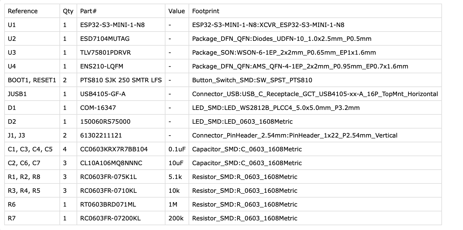
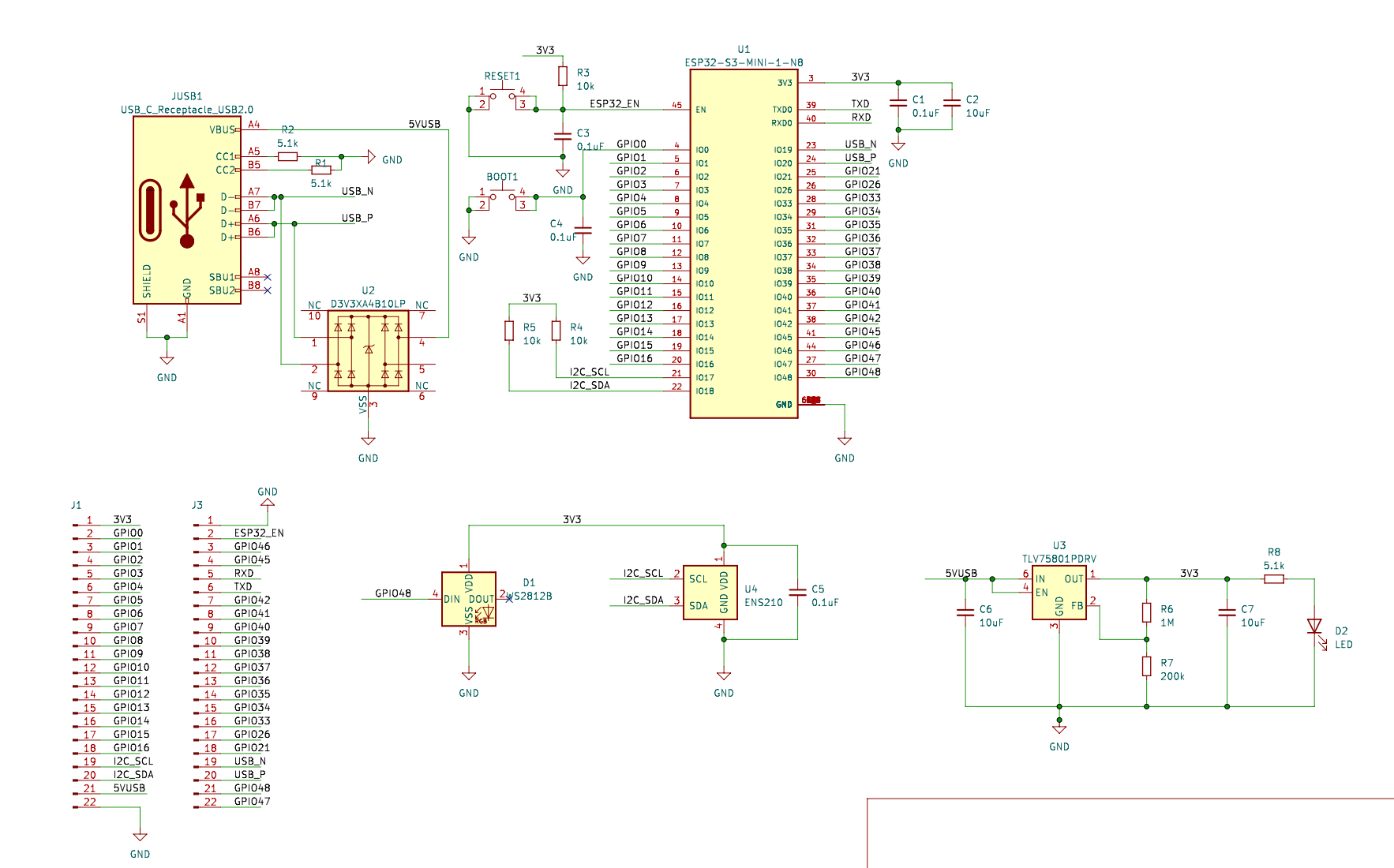
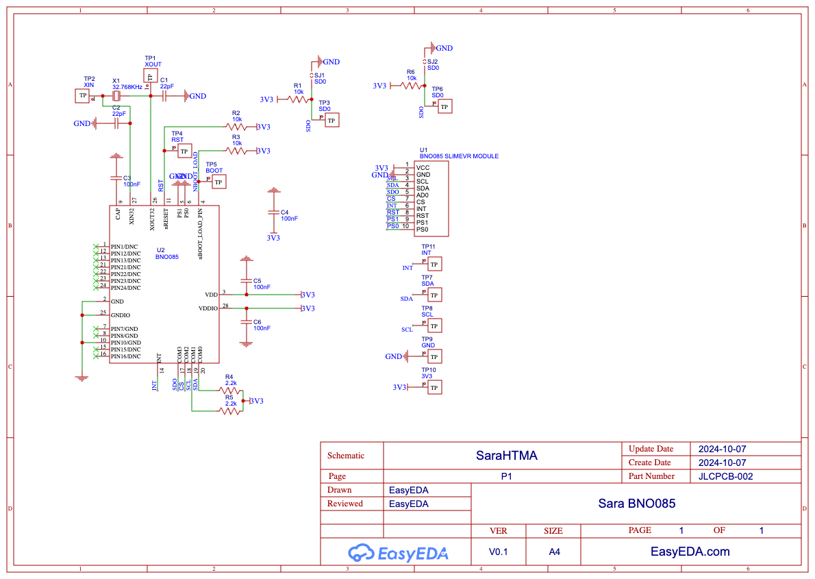
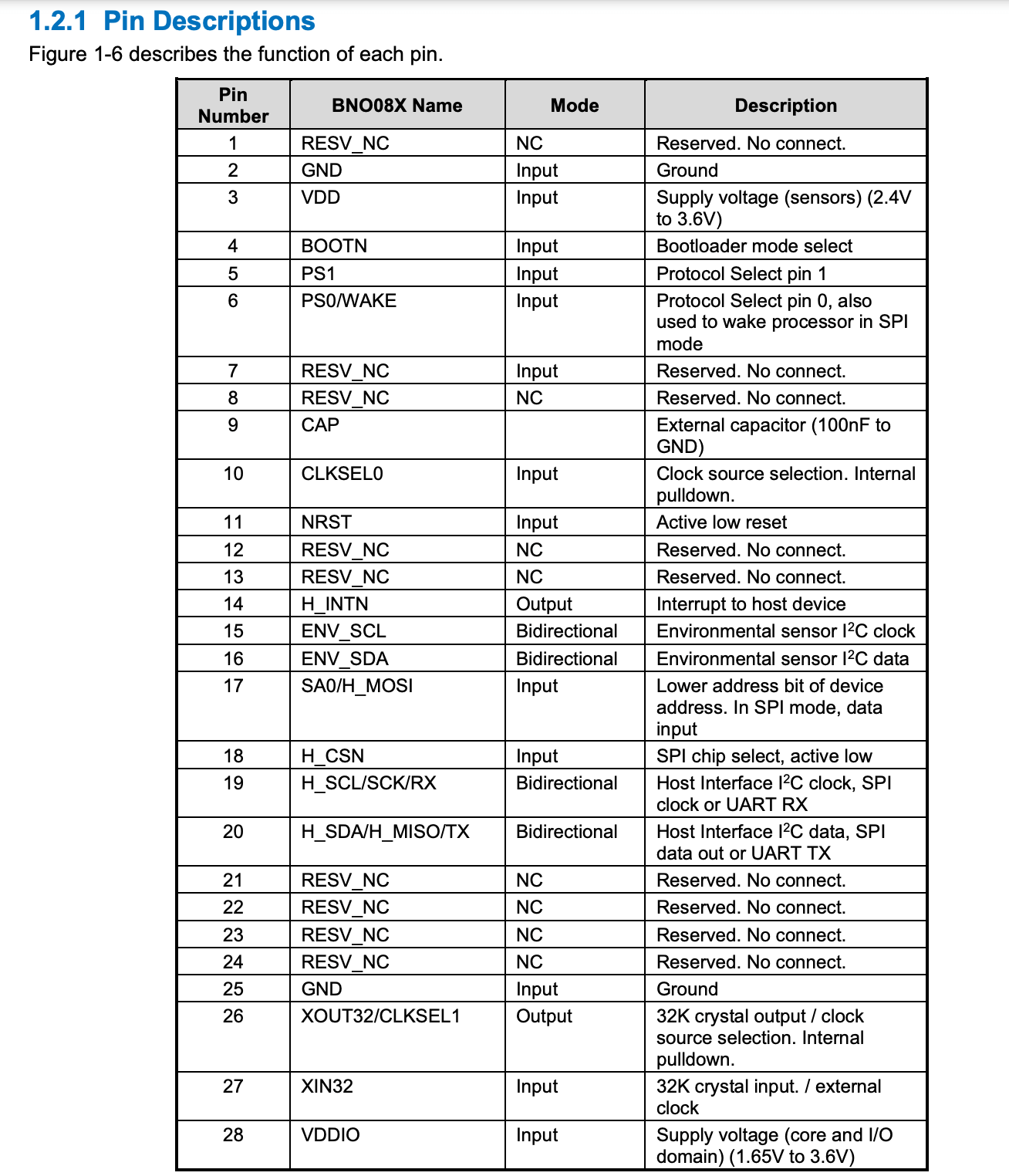
BNO082: These schematics were made in Easy EDA
The BNO connected to an external microcontroller via the I2C interface. It is essentially 3 sensors in one device: an advanced
triaxial 16bit gyroscope, a versatile, leading edge triaxial 14bit accelerometer and a full performance geomagnetic senso.
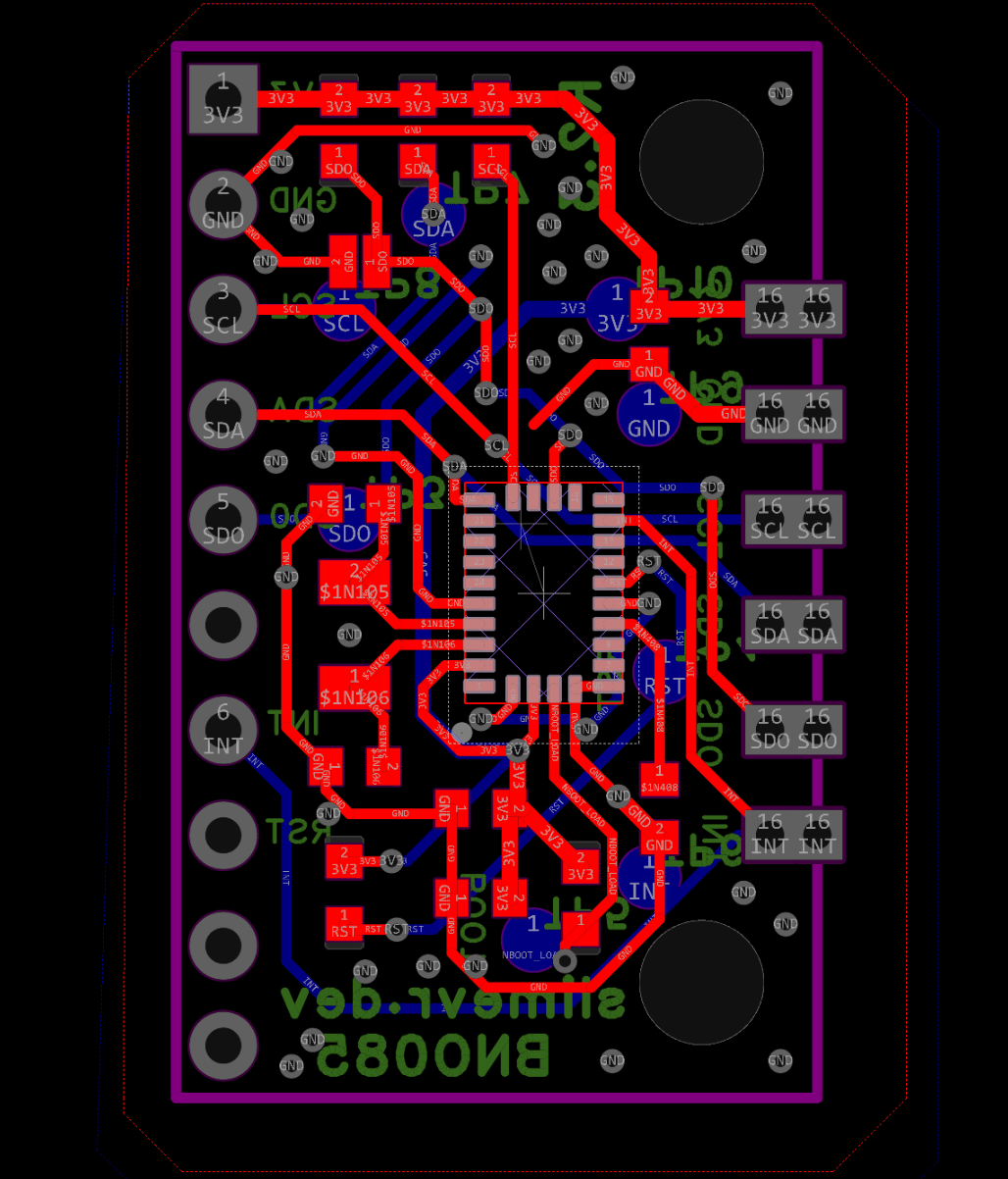
Example BNO PCB Image from Open Source Hardware Lab
Group Assignment:
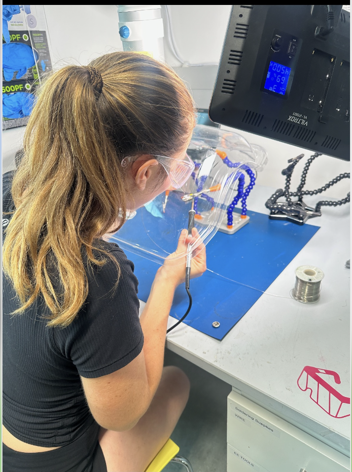
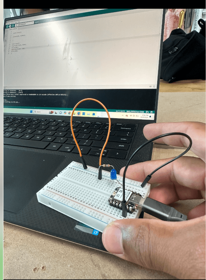
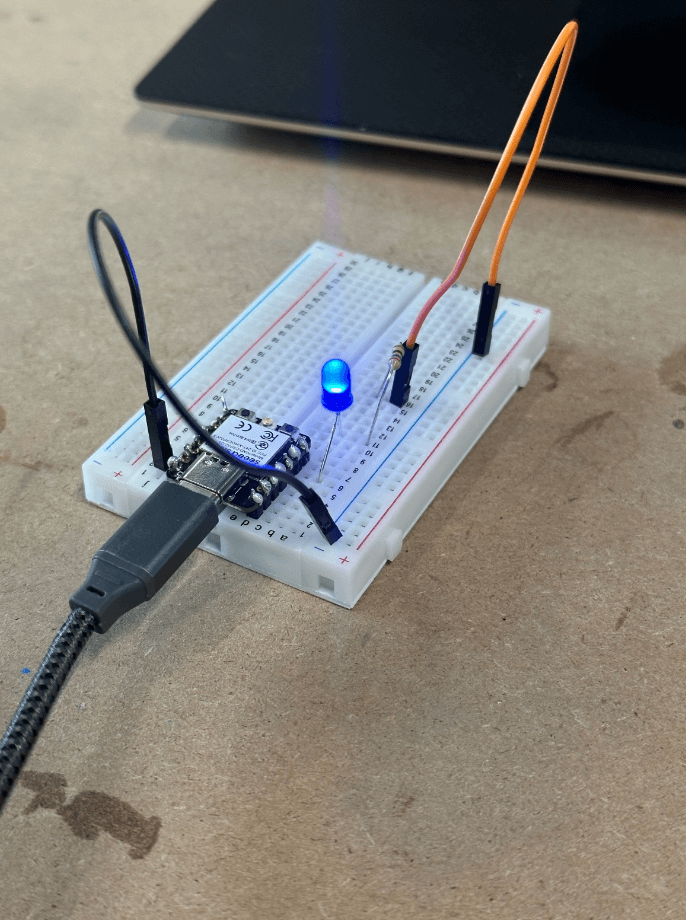
Below is the Arduino code that we provided. Originally, we thought we could simply plug & play our LED into the breadboard; but,
we ended up soldering the microcontroller so it could fit in the breadboard.
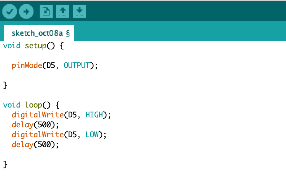
What does this code do?
Reflection 🤔
This week's electornic's module includes a lot of growth & remains a work in progress for me. I have better understanding of electronics design and building PCB boards. Now, I need to take the actual steps into building it.
Project Resources 🔗
How to Design an ESP32 PCB Board
Build Custom ESP32 Boards From Scratch! | the Complete Guide to Designing Your Own ESP32-S3 and C3
BNO085 Module Example Schematic & PCB
Ani HTMAA Page: Ani’s HTMAA Page was super helpful in my learning process. She kept a vectorized image of Neil's face on an adjacent screen to give her a relative idea of where the components should go. This whole time I’ve been confused how everyone is laying their board’s on Neil’s face, but it became clear it’s just the layout and the circuit routing.