Group Assignment
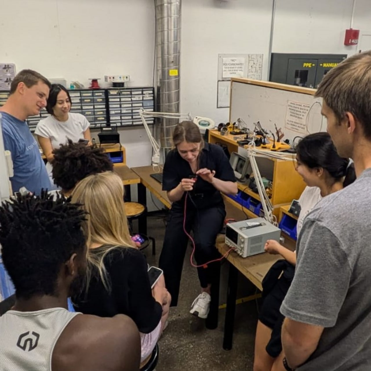
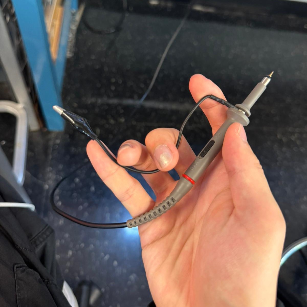
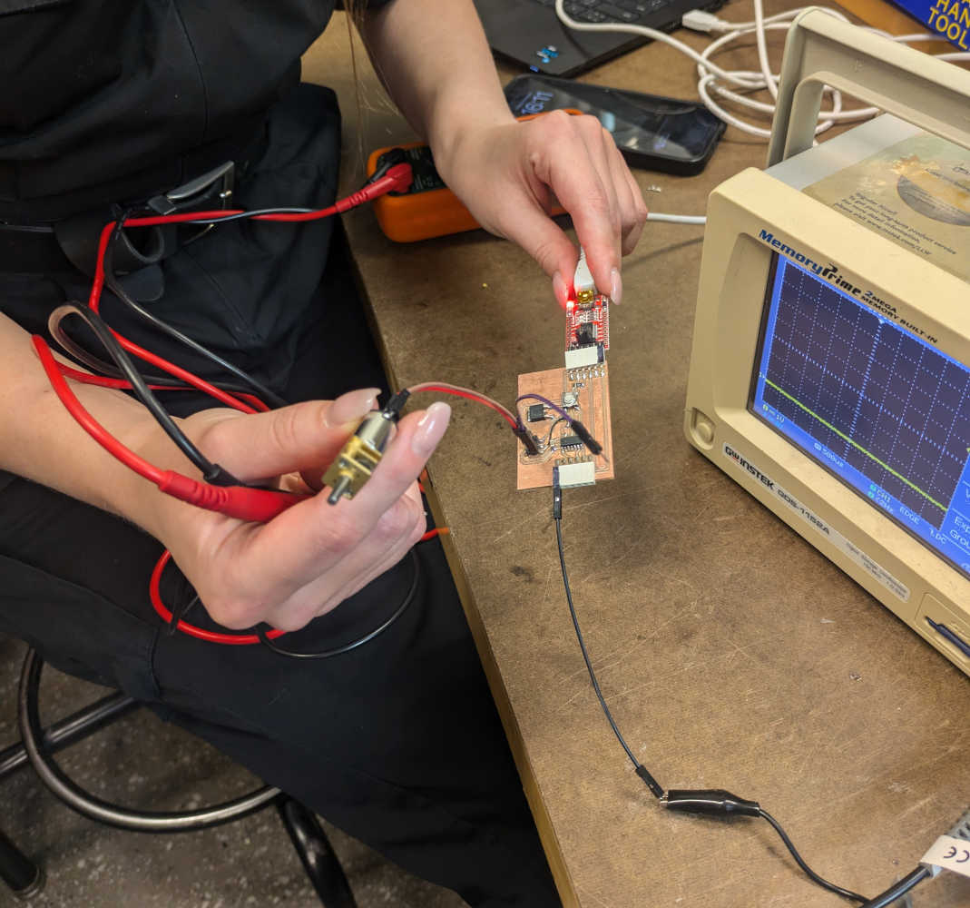
In the Architecture shop, we ran through some test equipment: using a multimeter to measure the input voltage of the Xiao, testing some loose resistors, the voltage of some batteries.
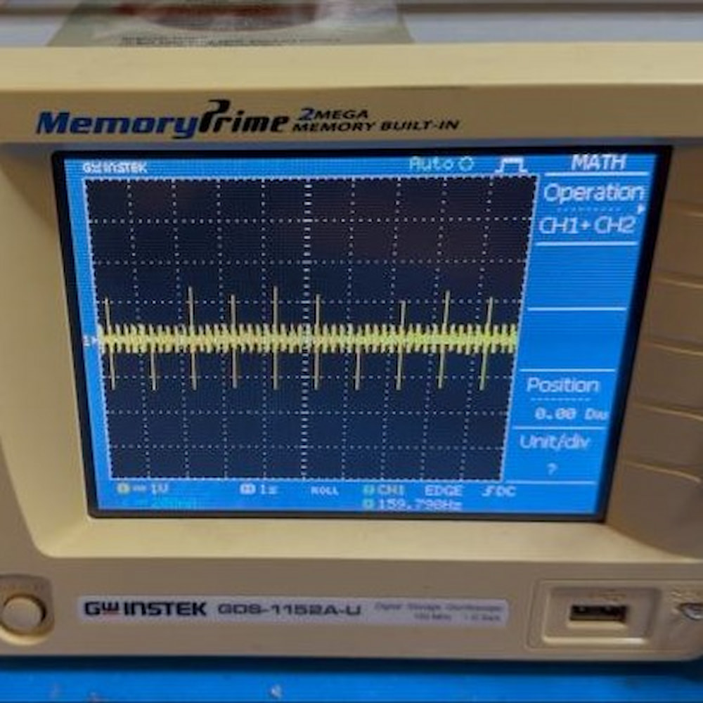
We also took a look at the oscilloscope: trying to zoom in on some Serial data packets being sent to a display and receiving waves from the function generator.
Later, xdd and I took a look at the equipment in N52, as we have access to that shop, and ran a similar test
Simple Board Design:
KiCad
Step 01
This week, I started developing a simple PCB board in multiple platforms. First, I tried out KiCAD. The first step was to instal the software.
Step 02
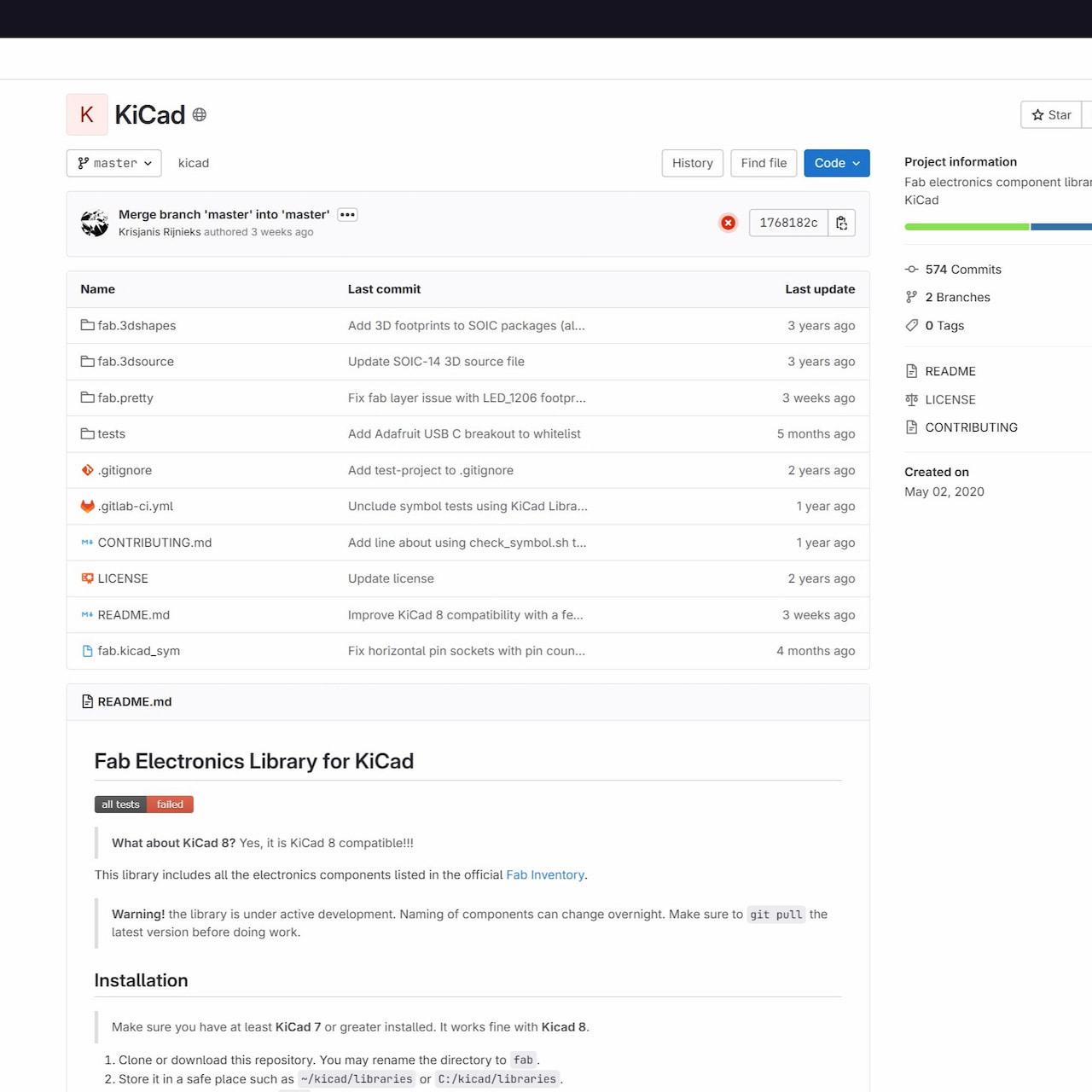
Then, I installed the fablab libraries into the my computer following the detailed instruction in the github site. https://gitlab.fabcloud.org/ pub/libraries/electronics/kicad
Step 03
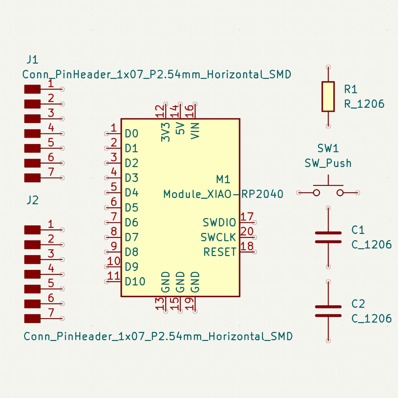
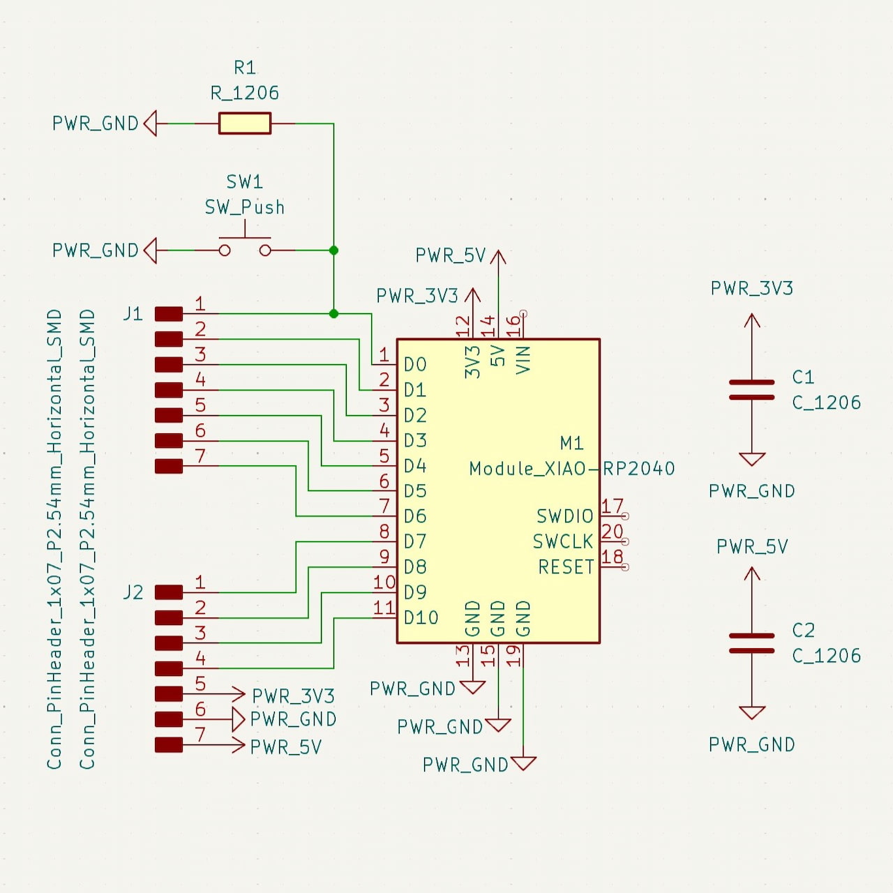
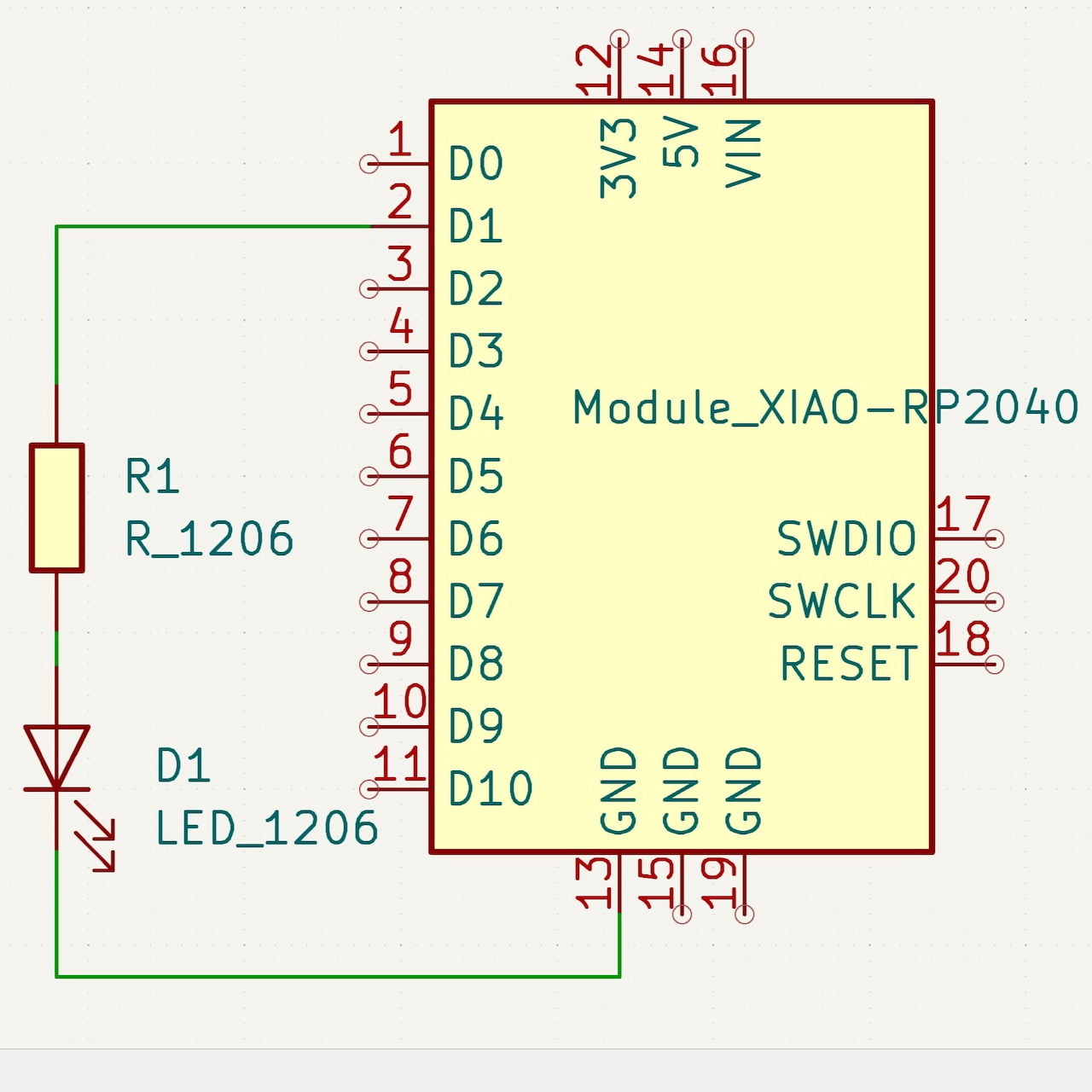
Next I had to identify every component I needed for a simple status check project via an LED. I decided to use the XiaoRP2040, an LED component, and a resistor. In the fablab library, these mapped to Module_XIAO-RP2040, LED_1206 and R_1206 respectively. So I went ahead and dropped them and connected them in my viewport.
Step 04
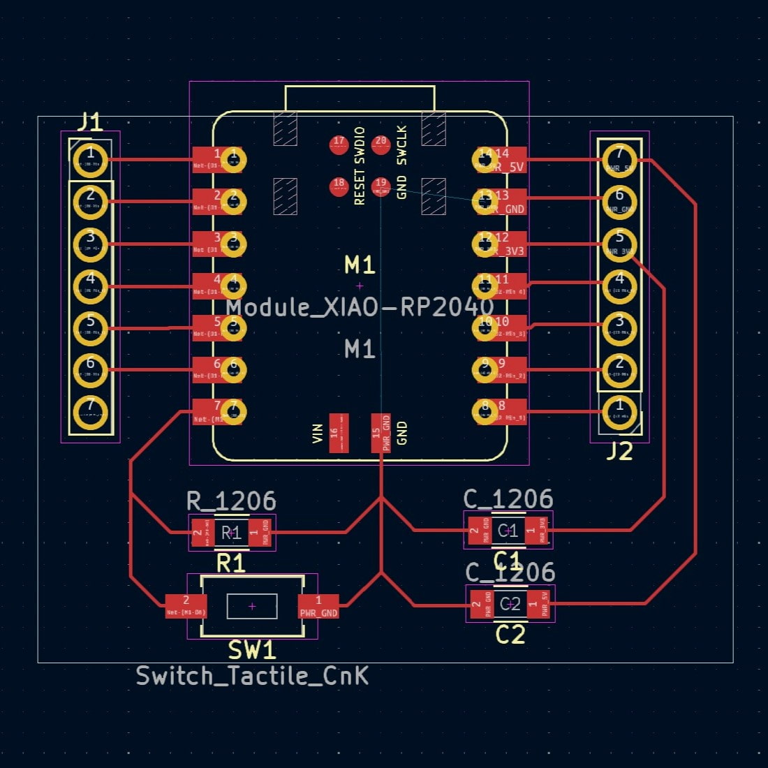
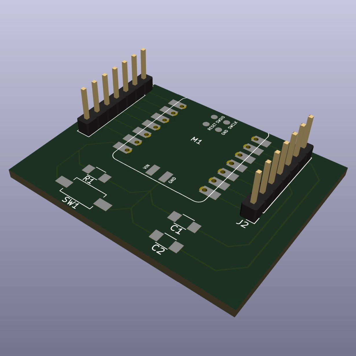
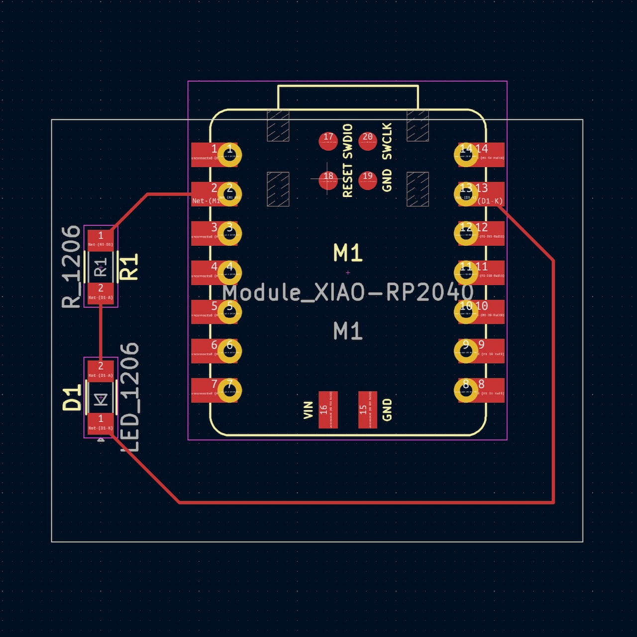
Once ready, I transition to the PCB-Editor. I reorganized the components and, using 0.16mm (recommend width), I make the traces for the connections. Next I traced the edge of the board, making sure the usb connection of the XiaoRP2040 was accessible.
Step 05
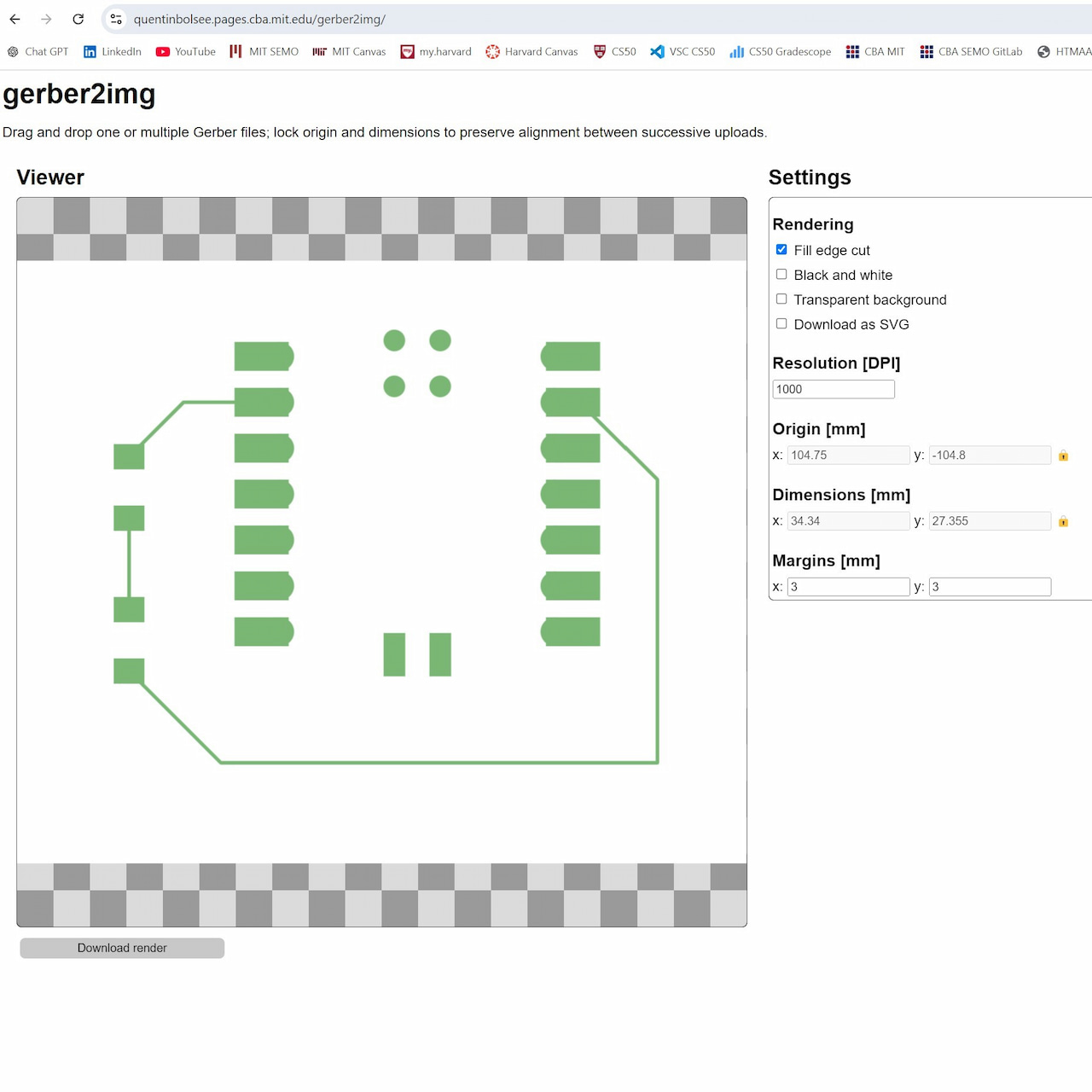
Finally, I exported the project to .gerber, and used the gerber2img site to extract the images for the actual fabrication of my board.
Simple Board Design:
SVG-PCB
Step 01
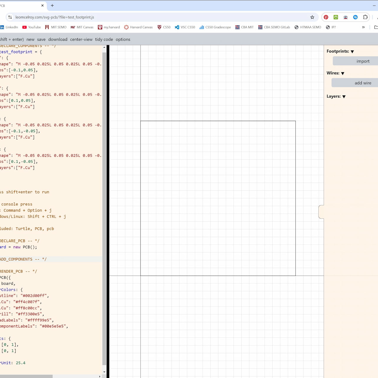
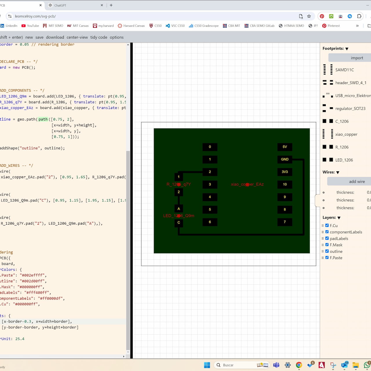
Then I tried the SVG-PCB site to make the exact same board. The platform already comes with the fablab components, though you can add components by just downloading them from github and dragging them in.
Step 02
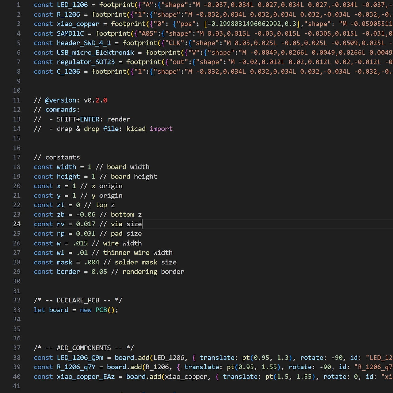
One of the cool things about this tool is that is allows for code code-based and GUI-based development. I did most things in the graphical interface, but adjusted or eliminated components in the code.
Step 03
So, I dropped in each component, organized them in a similar way I had done for the KiCad excercise and wired them using the connection tool. I could not make wierd shapes, but I did not dwell too much here. I will just ask Leo or another student how to do it later on. Seems simple to implement.
Step 04
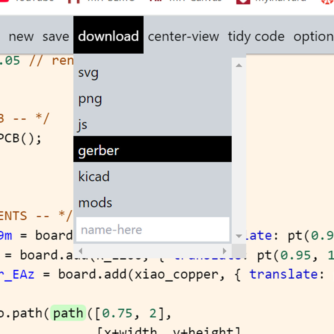
Unlike KiCad, you do not need to go into a new window like the PCB-Editor. Here you can simply hit export and get your gerber files. I am guessing this tool is best for quicker more creative designs, while the official software, like KiCad or Fushion, are best for more robust applications.
Step 05
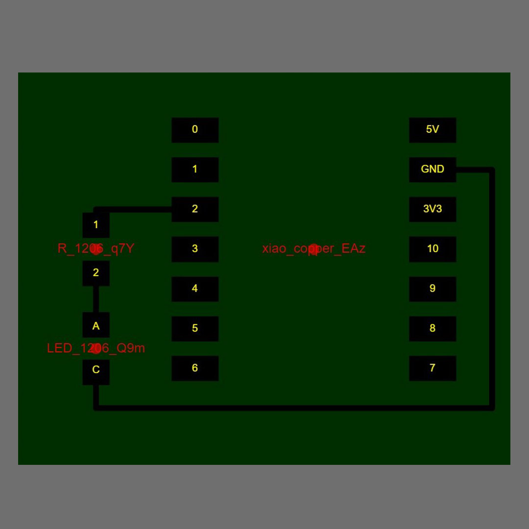
Once again, I used the berger2img site to create my fabrication images. In the end, I obtained very similar results. Will have to ask about the colors though, I have seen this usually in black and white.
Game of Life Board
After trying out multiple options, I decided to stick to KiCad and develop a board for next week.
In this case, I am thinking of a board for a Game of Life Simulation controled by a button.
Microcontroller: Module_XIAO-RP2040
Male Headers: 2 x Conn_PinHeader_1x07_P2.54mm_Horizontal_SMD
Description: 7-pin male headers for connecting to the Xiao's 14 pins.
Capacitors: C_1206 (Unpolarized, SMD)
Value: 0.1 µF ceramic capacitor for decoupling.
Button: SW_PUSH
Description: Standard momentary push button for control functions.
Resistors: R_1206
Value: 10kΩ (SMD)
