GROUP ASSIGNMENT
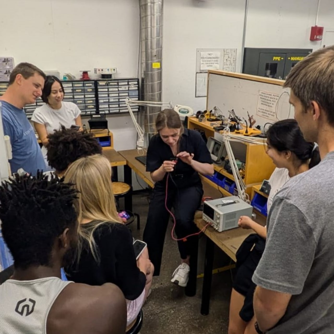
This week Diana was sick and we were not able to do a formal group assignment. Yet, many of us met at the fablab and shared ideas and insight about our input devices. Hope you get better soon Diana!

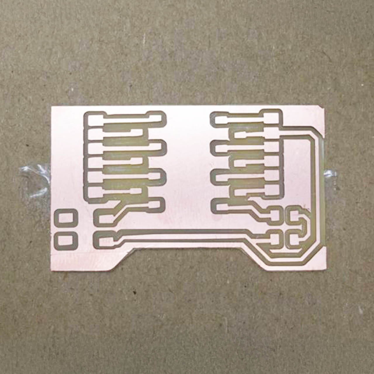
PCB REDESIGN
& MILLING
This design was based on the board design I developed for week 05, electronics production. The main difference is the added headers to attach my Xiao. This was, if I fry the microcontroller, I will be able to replace it, or I could reuse it in another board.

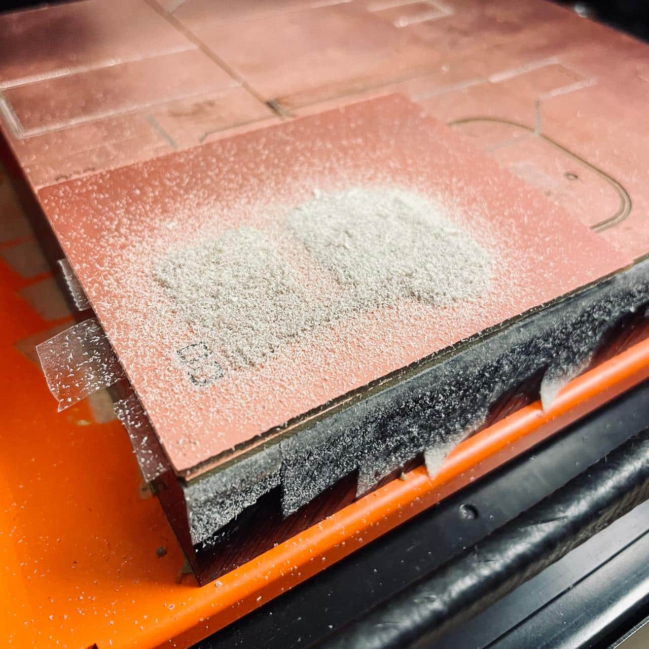

Next, I milled the board following the process outline in week-05, which is well documented on the MIT architecture shop website as well. I had some trouble with my edge cut mill, which did not go all the way through, and I used a knife to quickly complete the cut.
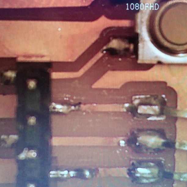
PCB SOLDERING
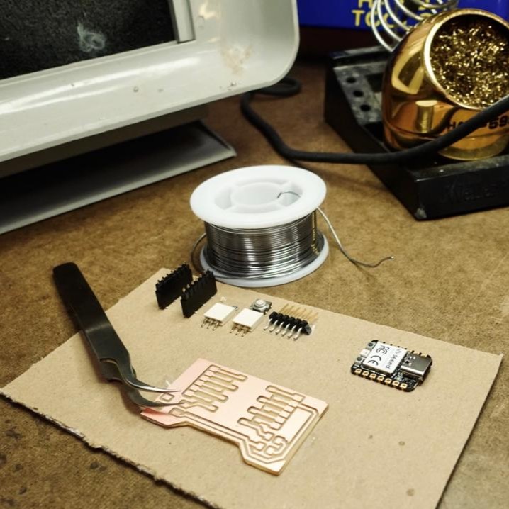
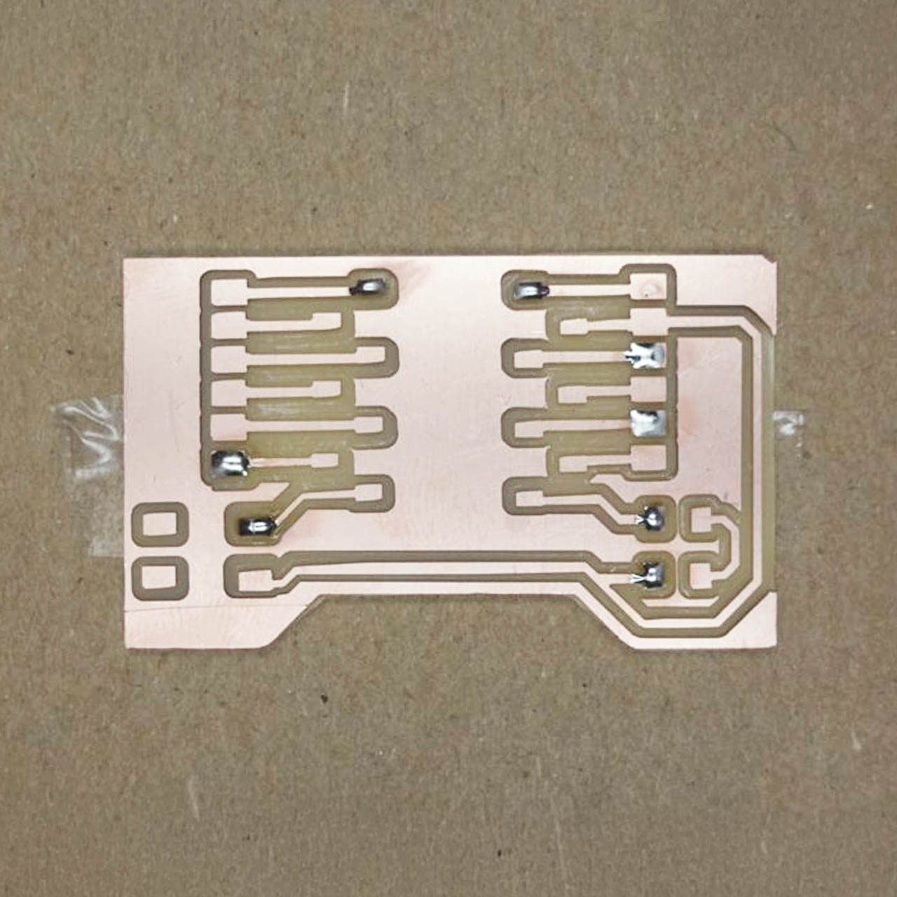
After cleaning the pcb, I moved onto soldering. First, I set up my station with my components, twizers, solder, iron, iron holder, iron cleaner, vacuum, and light. Then, I placed one drop of solder for each component to subsequently place them into place.

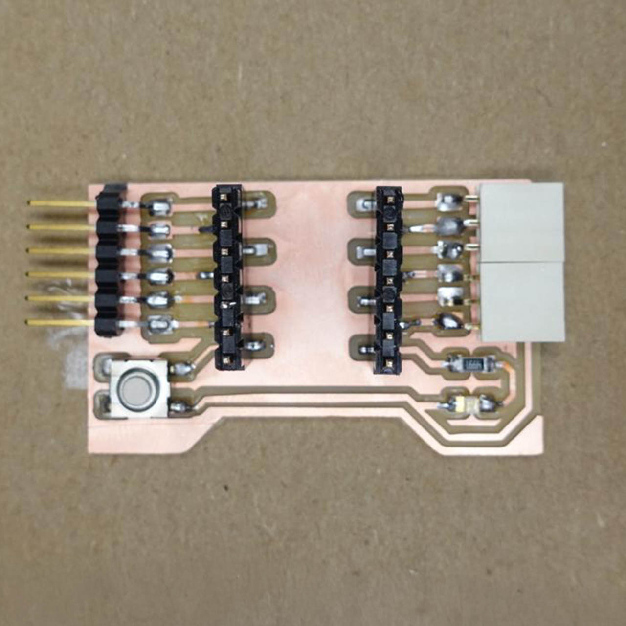
With the components in place, I proceeded to solder their remaining connections. For the Xiao headers, I was useful to test the fit of the actual Xiao and ensure the headers were located correctly. And so, mt board was ready for testing.
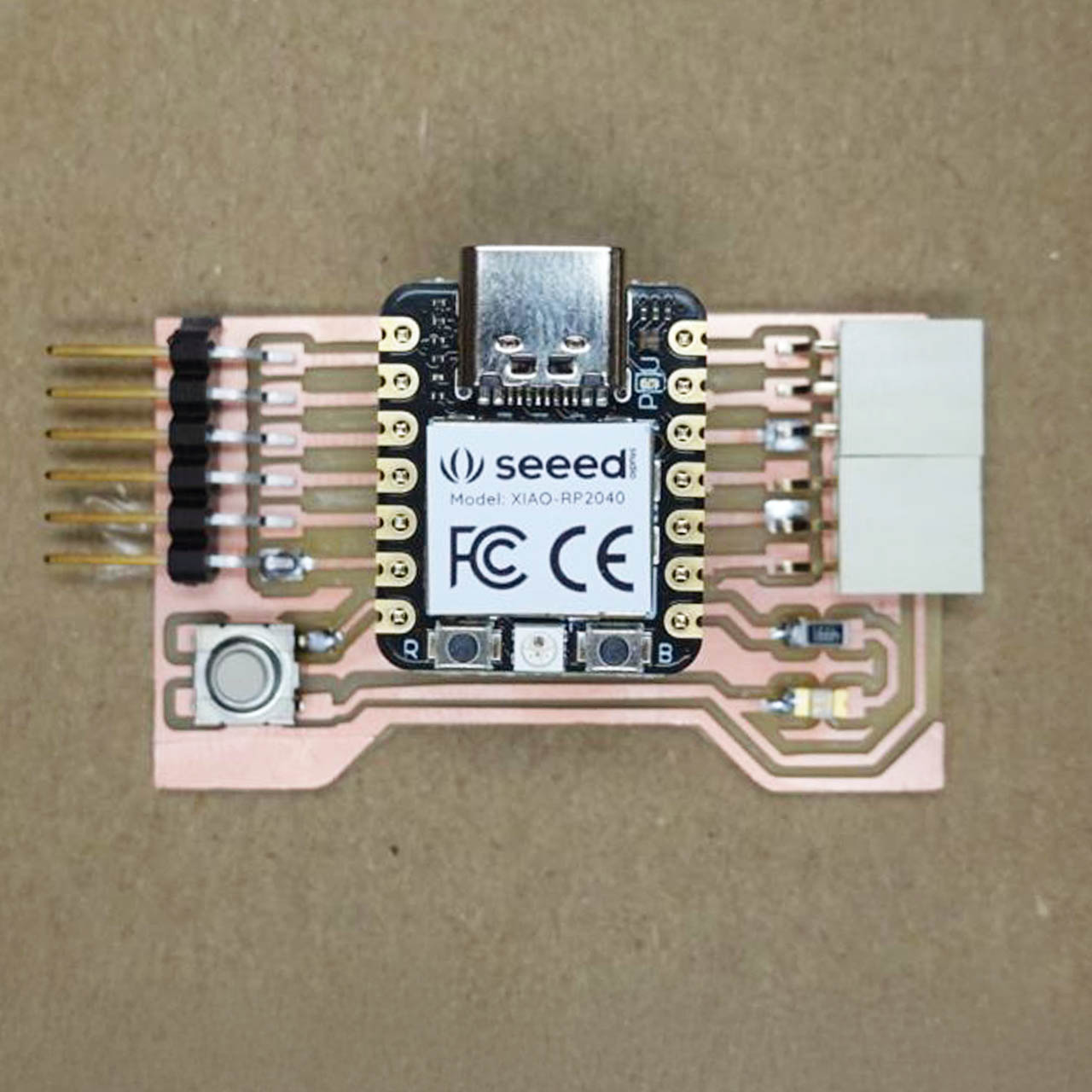

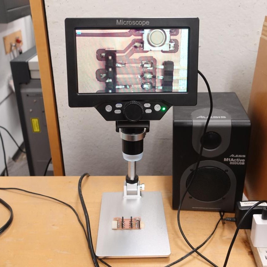

PCB TESTING
Testing D6 & D7
Switch Controlling D7 LED

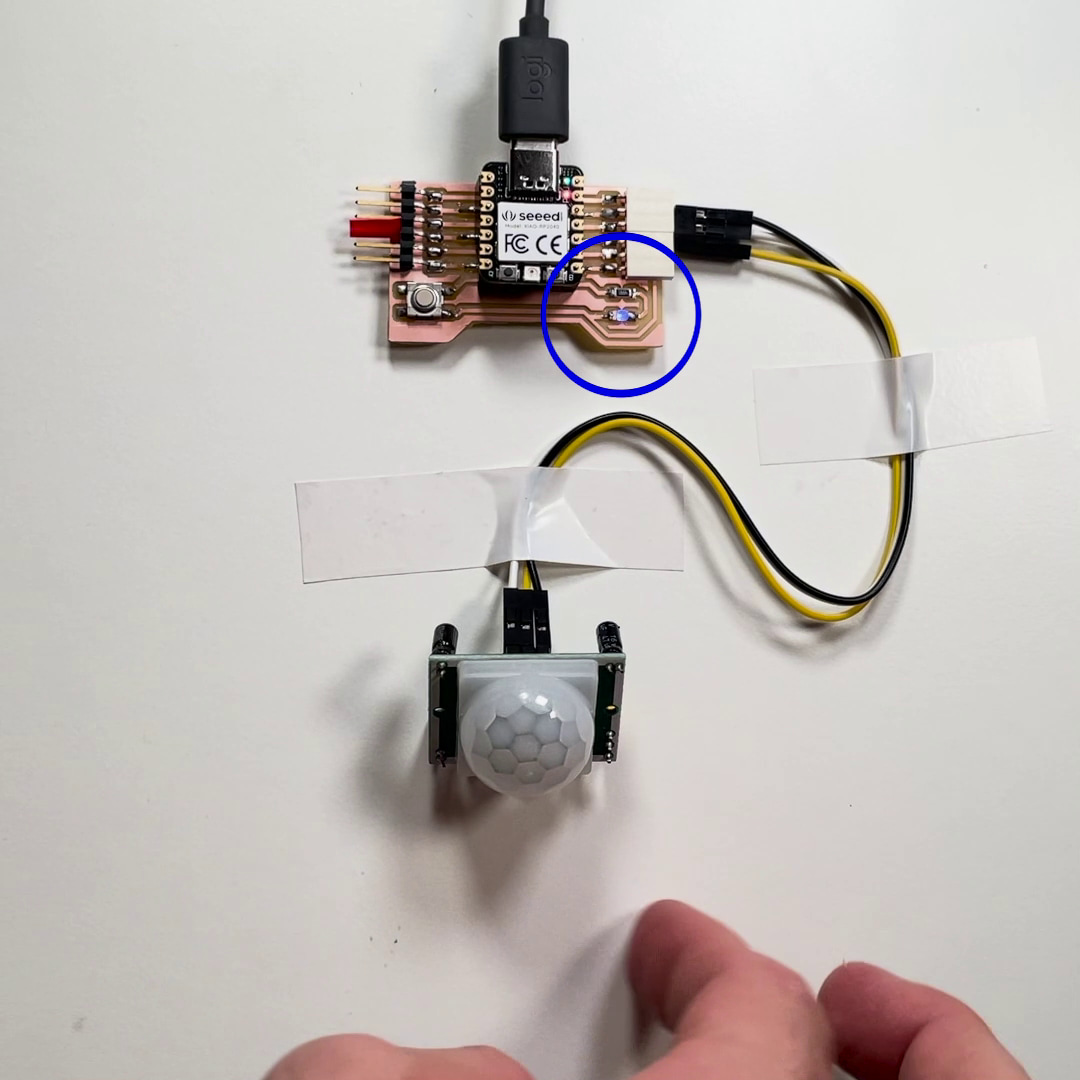
INPUT READING
I used a HC-SR501 PIR Motion Sensor to read the movement of my hand. A PIR (Passive Infrared) sensor is an electronic device that detects motion by measuring infrared (IR) light radiating from objects in its field of view. My wiring was as follows: PIR VCC - Xiao 3c3.V, PIR GND - Xiao GND, PIR OUT - Xiao D10