Welcome to Week 5
Electronics Design
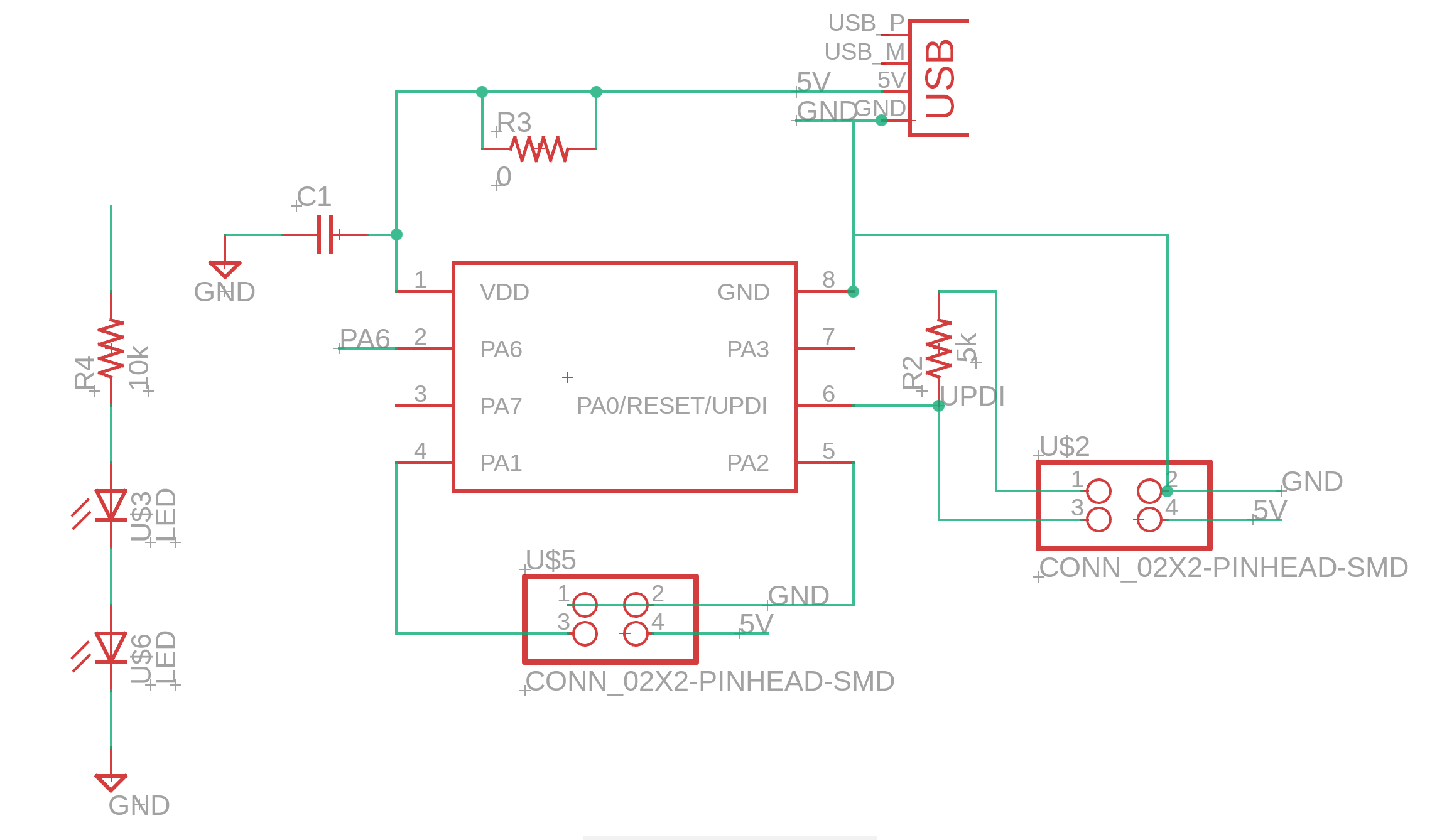
This week was particularly rough to say the least. For this week's project I felt like I knew absolutely nothing. I understand the basics of electronics (having taken electronics classes) but was unfamiliar with practical application. After lecture, recitation, and Anthony's intro for the EECS students, I will still at a complete loss. The problem wasn't with using the software (Fusion was actually pretty straightforward), but rather how to actually design something that would work in real life. My original mission was to make a PCB to control a stepper motor, but this proved impossible under my time constraints and lack of knowledge. So I decided to just make a simple set up using a few LEDs, switches, and the ATtiny412. To insure a steady power flow and prevent oversurges damaging the microcontroller I also included and pull up resistor and capacitor.
The microcontroller:

The schematic:

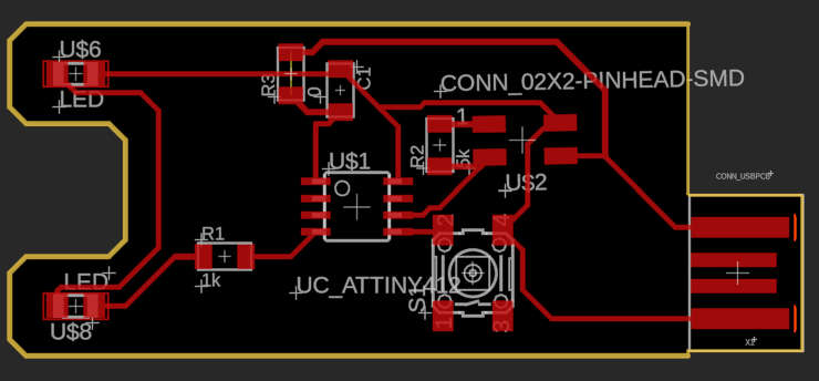
The PCB:

After designing the schematic above, I moved onto the PCB and drew connections. This was relatively easy, but overall Fusion's design rule check (DRC) was super helpful in fixing any issues
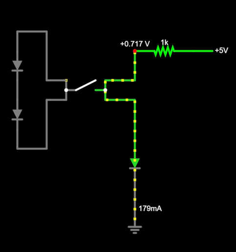
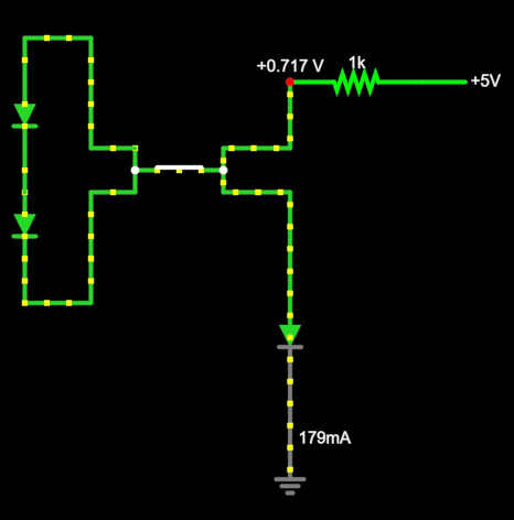
However unfortunately the DRC can't check for everything. As Anthony pointed out to me, my board had two big issues. For one, the USB connection wasn't located in a spot it could be accessed. Also, there was a huge flaw in the logic of the circuit and current flow. For that problem I used AVR8js CircuitJS1 Demo to visualize the current flow (as seen below). After fixes those issues and some others, I produced a new design and PCB.
Circuit Issues:


The final schematic:

The final PCB:

For the group project: During Anthony's intro session we were all able to check out some setups and play around with the multimeter


