Welcome to Week 8
Input Devices
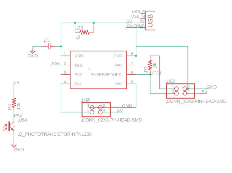
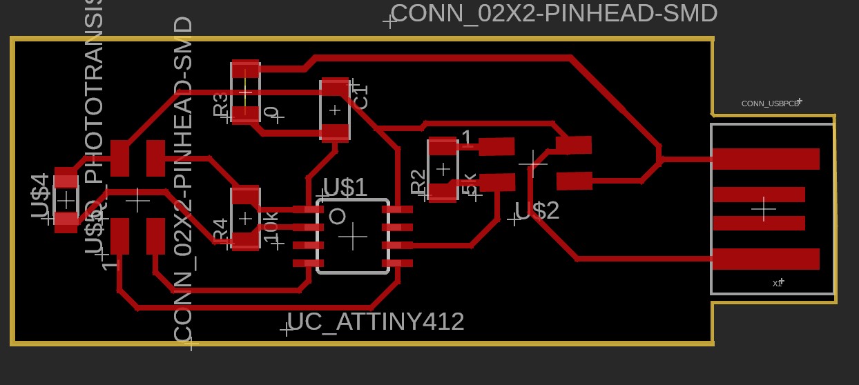
For this week's assignment I wanted to do something that would help towards my final project. Therefore I decided to do read the values of a phototransistor. I took my PCB from the other week and modified it a bit to add in a phototransistor. I definitely didn't get it first try and it took some fixing from Anthony but we eventually got there. This was the new schematic and PCB:


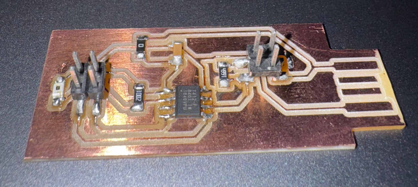
Next I milled out the board and sottered on the elements. For the microcontroller I used an Attiny 412.

Because I used an Attiny 412 I needed an FTDI adapter so that my board could properly communicate with my laptop. I wired up the board originally on the UPDI so download the code onto the board. For the code I just wrote a simple set up that recorded and printed the value of phototransistor every 100 milliseconds.


I ran into a lot of issues though. I seem to have melted my Attiny so I needed to remove and replace it with a new one. I also ran into the issue of downloading the MegaTinyCore library onto my computer. Apparently the certificate expired so I was receiving an error. Even when I tried to do it manually by creating a new file with the code, it still didn't work. Thankfully instead of giving up, Sam graciously offered me his laptop to complete the rest of the assignment. I copied my code over and tested it (which is why some pictures or me taking a picture of Sam's screen).

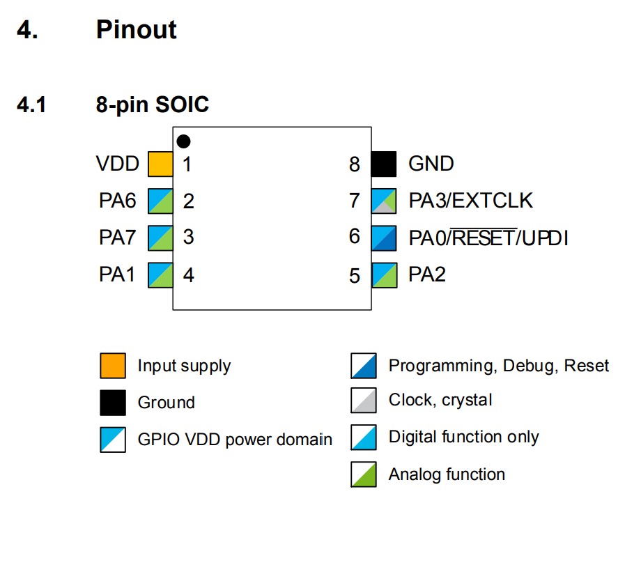
Unfortunately ran into another issue of my serial monitor not showing any output. When I looked at the data sheet it said I was using the correct Rx and Tx pins to serial communicate but turns out those were secondary ones so I looked up how to swap what was being read and corrected the problem.


Finally I was able to get some values of my phototransistor. The values did change when I altered the amount of light. Unfortunately I didn't get good pictures of this because it was late and I wasn't using my computer so I was in a bit of a rush to return it to Sam.


