
Can I make an automatic card dealer? (PCB Part #1) #
I have never designed a PCB before, so this week was a new challenge for me!
Group Assignment #
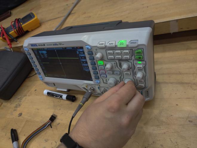
For our group assignment, we went over different ways to observe and debug microcontrollers. We used a multimeter and two different oscilloscopes to look at mixed electrical signals.
I’ve wanted to make an automatic card dealer for a while, because my family plays a lot of card games and they are quite expensive! An automatic card dealer essentially has two motors, one to rotate the actual dealer at 90 degree (or other angles depending on how many people are playing) intervals to distribute cards, and another small motor that spins on the bottom of the deck to actually move cards one at a time out of the dealer.

I decided to design a PCB for the dealer this week. I wanted to use a servo for the rotation and a brushed dc motor for the card extruder. I will be using the Xiao rp2040 because it is compatible with Arduino IDE and can output several PWM signals, which are necessary for driving motors.
I will be trying out KiCad to make this schematic! I downloaded the symbol and footprint libraries from a very helpful git library.
For the DC motor, I decided to use a motor controller in the fab library, the Toshiba TB67H451FNG. Here is the link to the datasheet and information. The datasheet provides a useful schematic of an application example:

The motor driver takes a 5V input, two PWM inputs from IN1 and IN2, a V_ref, and outputs two signals to the brushed dc motor.
The datasheet recommends a 0.1 uF ceramic capacitor and a 100 uF electrolytic capacitor to filter out a large range of signals from the 5V, as well as a 0.1 uF capacitor for the Vref.

One part of the circuit example we are not using is the RS to ground signal, a resister for current detection, because we are not expecting large ranges of currents for our PCB.

But! I learned I have to be careful with PWM signals. There are several pins on the rp2040 that can output PWM signals, but two pins sometimes share the same “slice” of a PWM signal, which apparently is one instance of a PWM signal that outputs to both slices. I decided to use D0 and D1 on the xiao, or P26 and P27 on the rp2040, for the 2 PWM inputs on the motor controller.

Now for the servo! A servo needs three connections, a PWM control, a 5V power input, and then ground. Simple enough? I connected these to horizontal header pins near the edge of the board to make it easier to connect when manufactured!

Schematic So Far #

Here’s what the PCB looks like so far:

As you can see, I’m having a lot of issues with intersecting traces. To fix, I will use a 0 Ohm resistor to jump over some traces.
I found that I needed the jumps between capacitor 3 and ground, and for the two input PWM signals for the motor driver


I also added my name after adding the board outline because I had some negative space! Here are the gerber files generated for the traces and edges.
Reflections: #
- PCB design is very different from the CAD and mechanical design I’m used to doing, I feel like it’s much more specific and troubleshooting is more of a “black box”
- Planning the layout requires a lot of careful thinking, and I think it would have been helpful for me to draw the traces and footprints on paper first to visualize the geometry and sort out any constraints.
- Reading the datasheet and specs for the components and microcontroller is very important! I was paralyzed about what I wanted to do and what I needed to include initially, but I realized I just needed to figure out what I wanted to do (servo and dc motor), then read the datasheet and start from there! Especially for the PWM signals, I was able to find out what to do after carefully reading the specs for the Xiao rp2040 and finding how to use the slices for PWM signals.